2 minute read
6.4.2 Valve clearance – Check and adjustment

from MTU 12V4000M23F_ 12V4000M23S_ 16V4000M23F_ 16V4000M23S_ MS150068_01E Diesel Engine Operating Instruc

Preconditions
☑Engine is stopped and starting disabled. ☑Engine coolant temperature is max. 40 °C. ☑Valves are closed.
Special tools, Material, Spare parts
Designation / Use Feeler gage Torque wrench, 60-320 Nm Socket wrench, 24 mm Engine oil
Part No. Qty. Y20010128 F30452768 F30039526 1 1 1
Preparatory steps
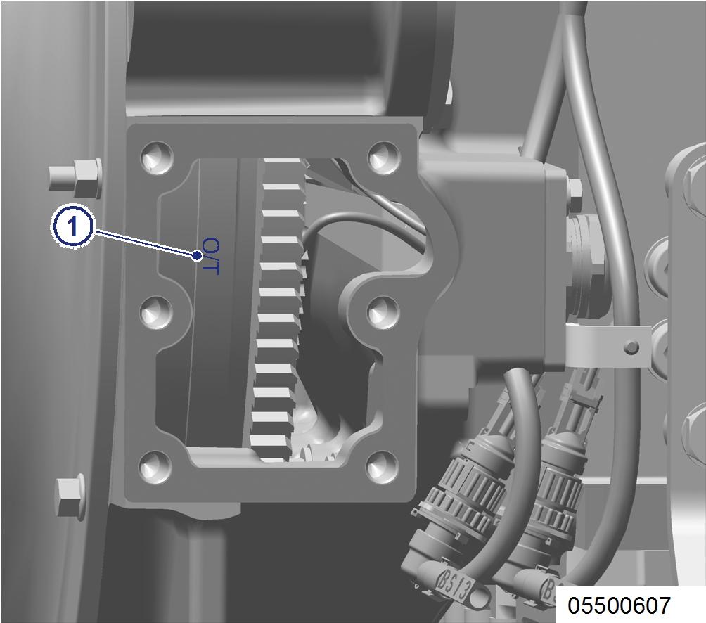
1. Remove cylinder head cover (→ Page 176). 2. Install barring gear (→ Page 162). 3. The OT mark (1) on the flywheel (if applicable) must not be used for reference.
4. Rotate crankshaft with barring tool in engine direction of rotation until marking “OTA1” and pointer are aligned.
1 Cylinder A1 is in firing TDC 2 Cylinder A1 is in overlap TDC I Inlet valve X Exhaust valve
1 Cylinder A1 is in firing TDC 2 Cylinder A1 is in overlap TDC I Inlet valve X Exhaust valve


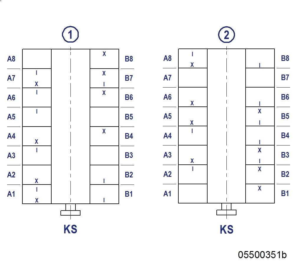
1. Check TDC position of piston in cylinder A1: • If the rocker arms are unloaded on cylinder A1, the piston is in firing TDC. • If the rocker arms are loaded on cylinder A1, the piston is in overlap TDC. 2. Check valve clearance adjustment with engine cold: • Inlet valves (long rocker arm) = 0.2 mm • Exhaust valves (short rocker arm) = 0.5 mm 3. Check all valve clearances at two crankshaft positions (firing and overlap TDC for cylinder A1) as per diagram. 4. Use feeler gage to determine the distance between valve bridge and rocker arm. 5. If the deviation from the reference value exceeds 0.1 mm, adjust valve clearance.
Adjusting valve clearance
1. Release locknut (1). 2. Insert feeler gage (3) between valve bridge and rocker arm. 3. Using Allen key, set adjusting screw (2) so that the specified valve clearance is provided.
Note: Feeler gage must just pass through the gap. 4. Pull feeler gage (3) between valve bridge and rocker arm.
5. Tighten locknut (1) to the specified tightening torque, holding adjusting screw (2) firmly.

Name
Locknut Size Type M16 x 1.5 Tightening torque Lubricant
(Engine oil) Value/Standard 90 Nm + 9 Nm
6. Replace or rectify adjusting screws and/or locknuts which do not move freely. 7. Check valve clearance.
Final steps
1. Remove barring gear (→ Page 162). 2. Install cylinder head cover (→ Page 176). 3. Enable engine start.