12 minute read
6.22.9 Diagnostic features of EIM

from MTU 12V4000M23F_ 12V4000M23S_ 16V4000M23F_ 16V4000M23S_ MS150068_01E Diesel Engine Operating Instruc

Diagnostic lamp (DILA)
A diagnostic lamp (LED, blue) is integrated in the housing of the Engine Interface Module (EIM). It indicates the operating status of the EIM.
Functions of diagnostic lamp DILA DILA lights Engine Interface Module (EIM) is OK. DILA dark EIM supply voltage missing or diagnostic lamp activation is faulty.
DILA flashes Hardware or software fault in the Engine Interface Module.
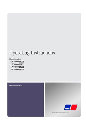
The diagnostic lamp (DILA) signals the following states:
1 Time in seconds 2 Timing: 1/8 s 3 Ready for operation 4 Application loader active 5 External RAM faulty 6 External FLASH faulty 7 No firmware 8 Application crashed
Fuse lamp (SILA)
A second indicator is the fuse lamp. This is also integrated in the housing of the Engine Interface Module. It indicates the status of the fuses. An orange LED is provided to allow diagnosis of a “tripped fuse” fault directly at the unit as it is often difficult to pinpoint a fault in the field without cabling diagrams. This LED is activated by the controller.
Functions of fuse lamp SILA SILA dark Norma operating state. SILA flashes orange One or more fuses have tripped.
1 Preamble 2 ECU current path failed (S1) 3 MCS current path failed (S2) 4 EMU current path failed (S3) 5 Starter voltage: Terminal 30, 31 not connected and
PR 10.0600.001 has value 1 or 2 (S4)
6 VSP current path failed (S5) 7 SLD current path failed (S6) 8 DDV current path failed (S7) 9 Gear monitoring current path failed (S8) 10 Emergency stop current path failed – 24V internal (S9)
11 ES pushbutton current path failed – 24V external (S10) 12 Key switch current path failed (S11) 13 SDAF 1+2 current path failed (S12) 14 PIM current path failed (S13) 15 Spare current path failed (S14) The failed current paths are signaled consecutively following the preamble (LED on for 4 seconds (1)). There is a pause lasting 4 seconds in between.
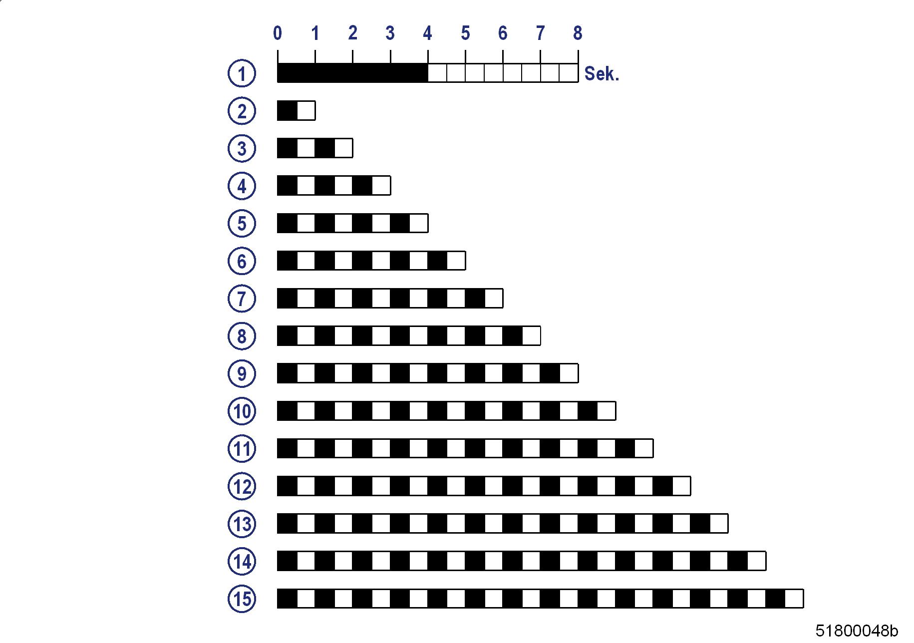
Sample flashing sequences
A Fuse S5 failure (1/2 second steps) B Fuse S1 and fuse S4 failure (1/2 second steps)
Note: These bit sequences are transmitted constantly.
Information about the status of the current paths of the EIM is also provided in the CAN message “Status internal power supply”.
7 Appendix A
7.1 Abbreviations
Abbreviation Meaning Explanation
ADEC Advanced Diesel Engine Control
Engine governor AL Alarm Alarm (general) ANSI American National Standards Institute Governing body for US American standards ETC Exhaust turbocharger BR Baureihe (Series)
BV Betriebsstoffvorschrift Fluids and Lubricants Specifications, MTU Publication No. A01061/..
CAN Controller Area Network CDC Calibration Drift Compensation Data bus system, bus standard Setting for drift correction with DiaSys in engine governor
CPP Controllable Pitch Propeller DILA Diagnostic lamp on EIM
DIN Deutsches Institut für Normung e. V. German Standardization Organization, at the same time identifier of German standards ("Deutsche Industrie-Norm")
DIS DL Display unit Default Lost Display panel Alarm: Default CAN bus failure
ECS Engine Control System ECU Engine Control Unit EDM Engine Data Module EIM Engine Interface Module EMU Engine Monitoring Unit SPC Spare Parts Catalog FPP Fixed Pitch Propeller GCU Gear Control Unit Engine management system Engine governor Memory module for engine data Interface to engine monitoring system
GMU Gear Monitoring Unit HAT Harbor Acceptance Test HI High HIHI High High HT High Temperature ICFN ISO - Continuous rating - Fuel stop power - Net IDM Interface Data Module IIG Initial Injector Equalization Alarm: Measured value exceeds 1st maximum limit Alarm: Measured value exceeds 2nd maximum limit
Power specification in accordance with DIN-ISO 3046-7 Memory module for interface data Entering of injector code with DiaSys in engine governor
IMO International Maritime Organization ISO International Organization for Standardization KGS Kraftgegenseite International umbrella organization for all national standardization institutes Engine free end in accordance with DIN ISO 1204
Abbreviation KS Meaning
Kraftseite LCD Liquid Crystal Display, Liquid Crystal Device LCU Local Control Unit LED Light Emitting Diode LMU Local Monitoring Unit LO Low LOLO Low Low LOP Local Operating Panel LOS Local Operating Station MCS Monitoring and Control System MG Message MPU Microprocessor Unit, Microprocessing Unit Explanation
Engine driving end in accordance with DIN ISO 1204
LOP subassembly
LOP subassembly Alarm: Measured value lower than 1st minimum limit Alarm: Measured value lower than 2nd minimum limit Control console, control panel
Microprocessor (unit)
TDC Top Dead Center P-xyz Pressure-xyz PAN Panel PCU Propeller Control Unit PIM Peripheral Interface Module RCS Remote Control System RL Redundancy Lost Pressure measuring point xyz Operating panel
Alarm: Redundant CAN bus failure SAE Society of Automotive Engineers U.S. standardization organization SAT Sea Acceptance Test SD Sensor Defect Alarm: Sensor failure
SDAF Shut Down Air Flaps SILA Fuse lamp SOLAS International Convention for the Safety of Life at Sea
SS
Safety System SSK Emergency-air shutoff flap(s) T-xyz Temperature-xyz TD Transmitter Deviation BDC Bottom Dead Center Emergency-air shutoff flap(s) on EIM
Indicated alarm is initiated by the safety system
Temperature measuring point xyz Alarm: Sensor comparison fault
VS Voith Schneider Voith-Schneider drive
WJ TC ZKP Water Jet Water jet drive
Tool Catalog Zugehörigkeit-Kategorie-Parameter Numbering plan for ADEC ECU signals
7.2 MTU contact persons/service partners
Our worldwide sales network with its subsidiaries, sales offices, representatives and customer service centers ensures fast and direct support on site and the high availability of our products.
Local support
Experienced and qualified specialists place their knowledge and expertise at your disposal. For locally available support, go to the MTU Internet site: http://www.mtu-online.com
24h hotline
With our 24h hotline and the outstanding flexibility of our service staff, we are always ready to assist you – either during operation, for preventive maintenance, corrective work in case of malfunction or changed operating conditions, or for spare parts supply. Your contact person in our Customer Assistance Center: E-mail: info@mtu-online.com
Tel.: +49 7541 9077777
Fax: +49 7541 9077778 Asia/Pacific: +65 6100 2688 North and Latin America: +1 248 560 8000
Spare parts service
Fast, simple and correct identification of spare parts for your drive system or vehicle fleet. The right spare part at the right time at the right place. With this aim in mind, we can call on a globally networked spares logistics system, a central warehouse at headquarters and on-site stores at our subsidiary companies, agencies and service workshops. Your contact at Headquarters: E-mail: spare.parts@mtu-online.com Tel.: +49 7541 908555
Fax: +49 7541 908121
8 Appendix B
8.1 Special Tools
Barring device
Part No.: F6555766 Qty.: Used in: 1 6.1.1 Engine – Barring manually (→ Page 162)
Feeler gage
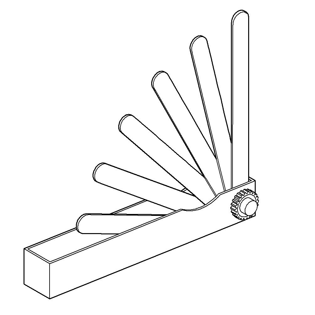
Part No.: Y20010128 Qty.: Used in: 1 6.4.2 Valve clearance – Check and adjustment (→ Page 173)
Filter wrench
Part No.: F30379104 Qty.: Used in: 1 6.7.2 Additional fuel filter – Replacement (→ Page 186)
Qty.: Used in: 1 6.7.3 Fuel filter – Replacement (→ Page 187)
Qty.: Used in: 6.14.1 Engine oil filter ‒ Replacement (→ Page 223) Qty.: Used in: 1 6.14.3 Centrifugal oil filter – Cleaning and filter sleeve replacement (→ Page 227)
Qty.: Used in: 1 6.15.8 Engine coolant filter – Replacement (→ Page 243)
Installation/removal jig
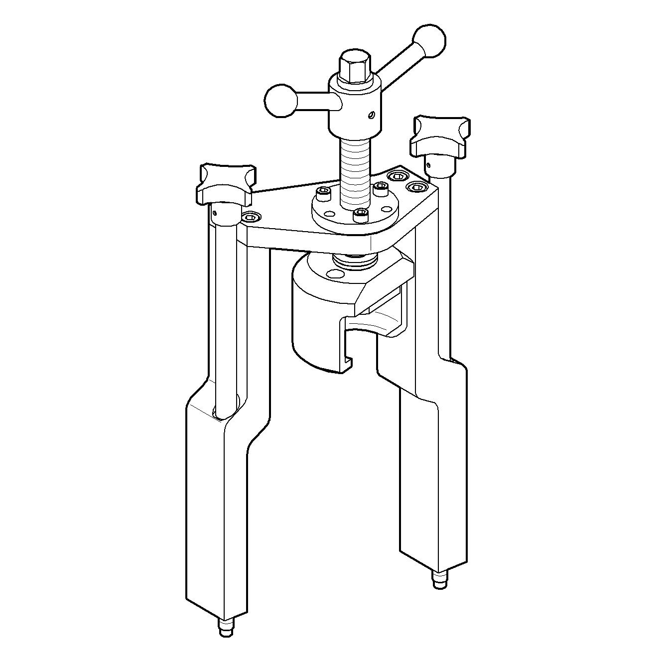
Part No.: F6789889 Qty.: Used in: 1 6.6.2 Injector – Removal and installation (→ Page 180)
Milling cutter

Part No.: F30452739 Qty.: Used in: 1 6.6.2 Injector – Removal and installation (→ Page 180)
MTU test kit
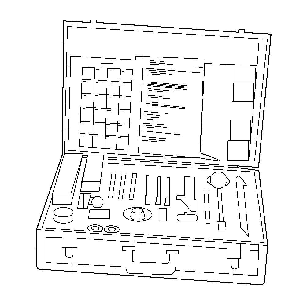
Part No.: 5605892099/00 Qty.: Used in: 1 6.13.3 Engine oil – Sample extraction and analysis (→ Page 221)
Qty.: Used in: 1 6.15.7 Engine coolant – Sample extraction and analysis (→ Page 242)
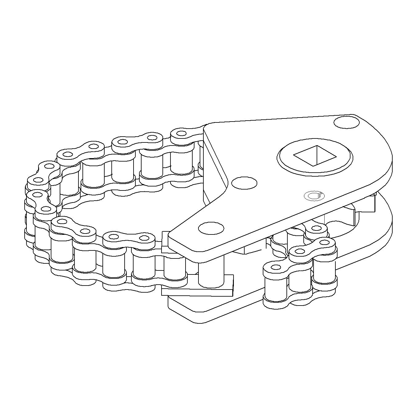
Ratchet
Part No.: F30027339 Qty.: Used in: 1 6.20.5 Coalescer filter element – Replacement (→ Page 257)
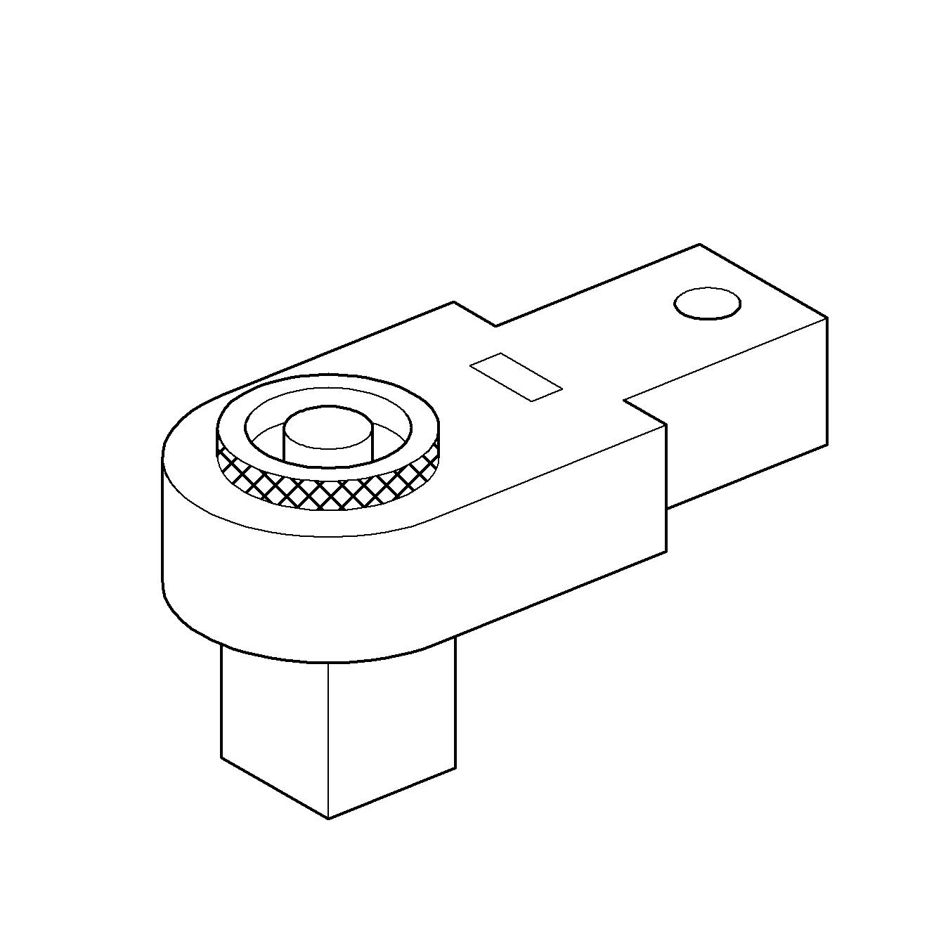
Ratchet adapter

Part No.: F30027340 Qty.: Used in: Qty.: Used in:
Qty.: Used in: 1 6.6.2 Injector – Removal and installation (→ Page 180) 1 6.7.8 Fuel prefilter with water separator – Filter element replacement (→ Page 195) 1 6.8.2 Compressor wheel – Cleaning (→ Page 205)
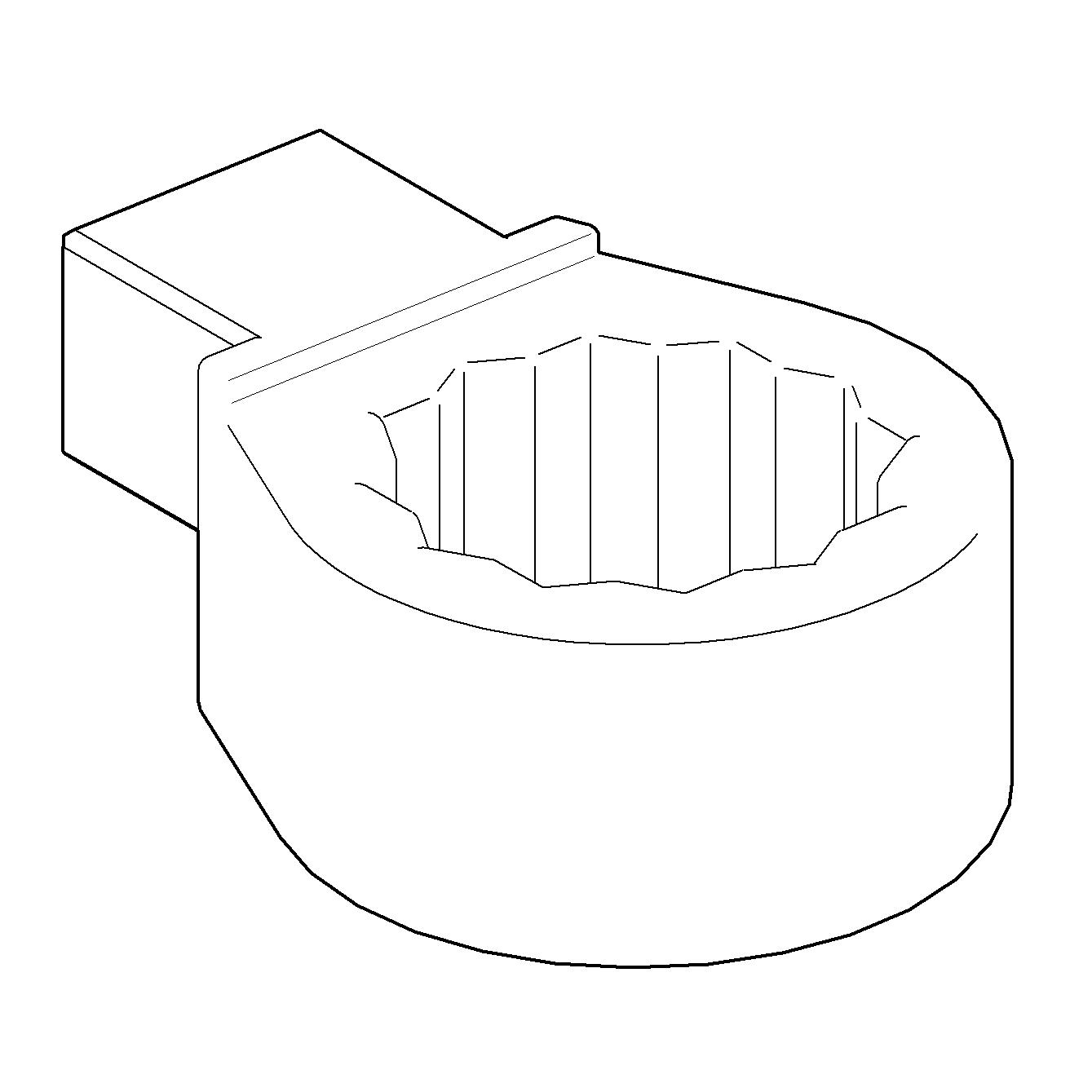
Ratchet adapter

Part No.: F30027341 Qty.: Used in: Qty.: Used in: 1 6.6.2 Injector – Removal and installation (→ Page 180) 1 6.13.2 Engine oil – Change (→ Page 219)
Ratchet with extension

Part No.: F30006212 Qty.: Used in: 1 6.1.1 Engine – Barring manually (→ Page 162)
Rigid endoscope
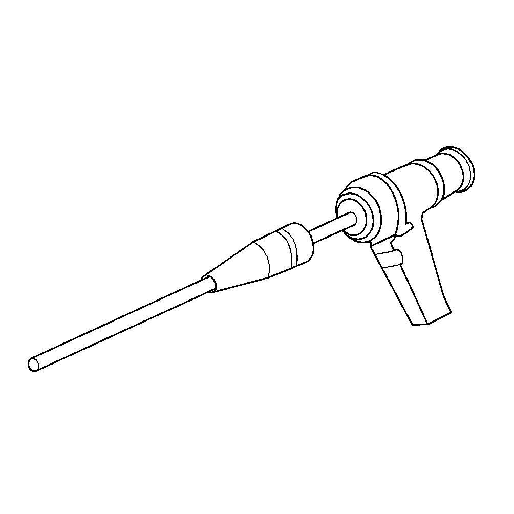
Part No.: Y20097353 Qty.: Used in: 1 6.2.1 Cylinder liner – Endoscopic examination (→ Page 165)
Socket wrench, 24 mm
Part No.: F30039526 Qty.: Used in: 1 6.4.2 Valve clearance – Check and adjustment (→ Page 173)
Steam jet cleaner
Part No.: Qty.: Used in: 1 3.14 Plant – Cleaning (→ Page 89)
Torque wrench, 0.5-5 Nm

Part No.: 0015384230 Qty.: Used in: 1 6.6.2 Injector – Removal and installation (→ Page 180)
Torque wrench, 10-60 Nm
Part No.: F30452769 Qty.: Used in: Qty.: Used in:
Qty.: Used in: 1 6.6.2 Injector – Removal and installation (→ Page 180) 1 6.7.8 Fuel prefilter with water separator – Filter element replacement (→ Page 195) 1 6.8.2 Compressor wheel – Cleaning (→ Page 205)
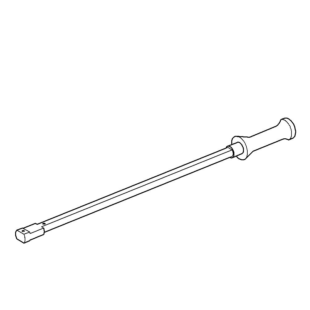
Torque wrench, 40-200 Nm

Part No.: F30027337 Qty.: Used in: 1 6.13.2 Engine oil – Change (→ Page 219)
Torque wrench, 6-50 Nm
Part No.: F30027336 Qty.: Used in: 1 6.14.3 Centrifugal oil filter – Cleaning and filter sleeve replacement (→ Page 227)
Torque wrench, 6-50 Nm
Part No.: F30027336 Qty.: Used in: 1 6.20.5 Coalescer filter element – Replacement (→ Page 257)
Torque wrench, 60-320 Nm
Part No.: F30452768 Qty.: Used in:
Qty.: Used in: 1 6.4.2 Valve clearance – Check and adjustment (→ Page 173) 1 6.6.2 Injector – Removal and installation (→ Page 180)
8.2 Index
Preheating unit 244
Numerics 12V 4000 M23F engine data, RheinSchUO, stage II, IMO
Tier II 56 12V 4000 M23S engine data, IMO Tier II, EPA Tier 2 62 12V 4000 M23S engine data, RheinSchUO, stage II, IMO
Tier II 59 16V 4000 M23F engine data, RheinSchUO, stage II, IMO
Tier II 65 16V 4000 M23S engine data, IMO Tier II, EPA Tier 2 71 16V 4000 M23S engine data, RheinSchUO, stage II, IMO
Tier II 68
A Abbreviations 277 Actuators – Overview 32 Additional fuel filter – Replacement 186 ADEC (ECU 7) – Fault codes 97 – Fault messages 96 After stopping the engine 88 Air filter – Removal and installation 215 – Replacement 214
B Battery-charging generator drive – Coupling condition check 251 Bilge pump – Relief bore check 252
C CDC parameters – Reset 266 Centrifugal oil filter – Cleaning 227 Checks – Prior to start-up 80 Coalescer filter element – Replacement 257 Compressor wheel – Cleaning 205 Contact persons 279 Controls 74 Coolant – Change 235 Cooler – Charge-air – Checking condensate drain for water discharge and obstruction 213 Crankcase breather – Oil mist fine separator – Replacement 171 Crankcase breather system – Overview 169 Cylinder – Designation 52 Cylinder head cover – Installation 176 – Removal 176 Cylinder liner – Endoscopic examination 165 – Instructions and comments on endoscopic and visual examination 167
D Designations – Engine sides and cylinders 52 Differential pressure gauge – Check 254 Drain and vent points 230 Drift compensation – Reset 266
E ECU 7 – Installation 271 – Removal 271 EMU 7 – Installation 272 – Plug connection check 269 – Removal 272 Engine – Barring manually 162 – Barring with starting system 164 – Emergency stop 87 – Main dimensions 53 – Start 77 – Stopping 86 – Wiring check 265 Engine Control Unit ECU 7 – Checking plug connections 268 – Installation 271 – Removal 271 Engine coolant – Change 235 – Draining 236 – Filter replacement 243 – Sample analysis 242 – Sample extraction 242 Engine coolant level – Check 234 Engine coolant – Filling 239 Engine governor ADEC (ECU 7) – Fault codes 97 – Fault messages 96 Engine Interface Module EIM – Removal and installation 273 Engine layout 28
Engine Monitoring Unit EMU 7 – Plug connection check 269 Engine mounting – Check 250 Engine oil – Sample extraction and analysis 221 Engine oil – Change 219 Engine oil filter – Replacement 223 Engine oil level – Check 218 Engine sides – Designation 52 Engine wiring – Check 265 Engine wiring harness – Overview 259
F Fault codes – Engine governor ADEC (ECU 7) 97 Fault messages – Engine governor ADEC (ECU 7) 96 Filter – Coalescer element – Replacement 257 – Engine coolant – Replacement 243 Filter sleeve – Replacement 227 Firing order 55 Fuel – Treatment system – Switching on 84 – Troubleshooting 95 – treatment system – Shutdown 85 Fuel filter – Replacement 187 Fuel prefilter – Flushing 193 Fuel prefilter – Draining 191 Fuel prefilter with water separator – Filter element replacement 195 Fuel prefilter with water separator – Rotary slide valve Orings – Replacement 197 Fuel prefilter – Differential pressure gauge – Adjustment 190 – Check 190 Fuel system – Venting 189 Fuel treatment system – Putting into operation 81 – Shutdown 85 – Switching on 84 H Hotline 279 HP pump – Filling with engine oil 177 – Relief bore check 178 HT coolant pump – Relief bore check 241
I Injector – Installation 180 – Removal 180 – Replacement 179 Intercooler – Checking condensate drain for water discharge and obstruction 213 Interface module EIM – Check 270
L Limit switch for start interlock – Check 267
M Maintenance schedule – Maintenance task reference table [QL1] 90 MTU contact persons 279
O Oil indicator filter – Check 225 – Cleaning 225 Operational checks 78
P Plant – Cleaning 89 Plug connections – Check 270 Preheater – Overhaul 247 – Function and leak-tightness – check 248 Product description 16 Pump capacity – Check 256 Putting the engine into operation after extended out-ofservice periods (>3 months) 75 Putting the engine into operation after scheduled out-ofservice-period 76
R Raw water pump – Relief bore check 249
S Safety notices, standards 15
Safety regulations – Auxiliary materials 13 – Environmental protection 13 – Fire prevention 13 – Fluids and lubricants 13 – Important provisions 7 – Maintenance work 10 – Organizational requirements 8 – Personnel requirements 8 – Repair work 10 – Safety notices, standards 15 Sensors – Overview 32 Service indicator – Signal ring position check 216 Service partners 279 Spare parts service 279 Starter – Condition check 217 Supplementary fuel filter – Overview 185
T Tasks – After extended out-of-service periods 79 Tasks after extended out-of-service periods (>3 weeks) 79 transport 9 Troubleshooting 92 – Fuel treatment system 95 Turbocharger – Overview 198
V Valve clearance – Adjustment 173 – Check 173 Valve gear – Lubrication 172
W Water drain valve – Check 253 Water level probe (3-in-1 rod electrode) – Check 255