7 minute read
Menu structure


1 “Vehicle” main menu 1.1 Doors and flaps 1.2 Reversing camera / doorway II camera (option) 2 “Assistance” main menu 2.1 Operating notifications 2.2 IBIS (integrated on-board information system) 3 “Trip computer” main menu 3.1 After start 3.2 After reset 4 “Monitoring” main menu 4.1 Supply pressures 4.2 Engine 4.3 Voltage 4.4 Operating notifications 5 “Events” main menu 5.1 Overview 5.2 Event 1 5.3 Event 2 5.4 Event n
Note:
This overview takes all possible items of optional equipment into account. Bus-specific menu structures may differ from bus to bus. Driver's area controls
Menu structure
Menu structure Main menus and submenus
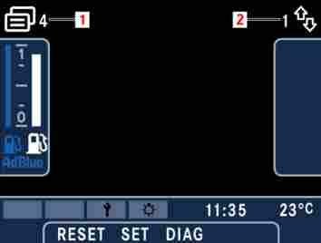
M54.00-1720-71 The menu system comprises five main menus arranged in a loop. The driver is able to browse from menu to menu using the main menu buttons on the steering wheel. For orientation purposes, the number (1) of the current main menu is displayed at the top left of the display window. Each main menu contains a series of submenus, which are also arranged in a loop. The number (2) identifying the submenu concerned is shown in the top right of the display. The only
Driver's area controls
Menu structure
menu in which this principle does not apply is the “Events” main menu, where the submenus are not numbered because the quantity of event notifications is continually changing.
Note:
When the “Next” main menu button is pressed briefly, the display advances to the next higher main menu. If the screen is showing the main menu with the highest number when the button is pressed, the display will return to the main menu with the lowest number (looped main menu structure).
Note:
When the “Back” main menu button is pressed briefly, the display goes back to the previous main menu. If the screen is showing the main menu with the lowest number when the button is pressed, the display will return to the main menu with the highest number.
Note:
When the “Next” arrow button is pressed briefly, the display advances to the next higher submenu. If the screen is showing the submenu with the highest number when the button is pressed, the display will return to the submenu with the lowest number (looped submenu structure).
Note:
When the “Back” main menu button is pressed briefly, the display goes back to the previous submenu. If the screen is showing the submenu with the lowest number when the button is pressed, the display will return to the submenu with the highest number.
Note:
After an ignition power cycle, the first submenu in the sequence will be displayed the first time a main menu is called up. As soon as the driver selects a different submenu, this submenu will be remembered by the system if the driver changes to a different main menu, i.e. the submenu last viewed in a particular main menu will be displayed immediately the next time the driver changes back to this main menu. In this way, the driver could select one submenu within each main menu to be a favourite so that, whenever the main menu buttons are pressed, the display would change from one favourite to another.
1. “Vehicle” main menu
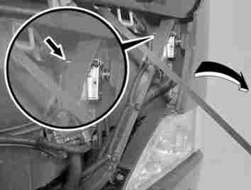
The “Vehicle” main menu displays the status of all doors, flaps and roof hatches. It also enables the driver to view the images transmitted by any cameras fitted in bus.
“Doors and flaps” submenu
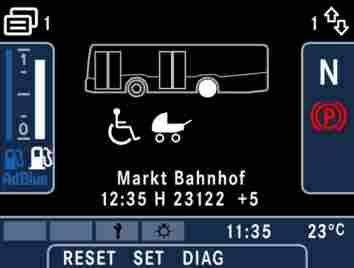
M54.00-1737-71 Closed doors, flaps and ramps are greyed out, while opened ones appear in white. The statuses of the engine compartment flap and roof hatches are also displayed. If the parking brake is applied, the wheel on the driven axle appears in white.
Note:
For operating/malfunction displays, refer to the “Opening/locking” section.
“Camera” submenu
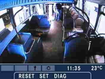
M54.00-1749-71 The bus may be fitted with cameras that enable the driver to monitor door 2 and the area behind the bus. The images from each of these cameras are displayed in their own submenu. Driver's area controls
Menu structure
Note:
If a reversing camera is installed, the image from the reversing camera appears on the display screen automatically when the driver engages reverse gear. The permanent display fields on the left- and right-hand sides of the screen are hidden by the camera image. Only the lower permanent display field remains visible.
Note:
The image from the door 2 camera appears on the display screen only when the driver opens door 2.
“Assistance” main menu
In the “Assistance” main menu, the driver can view information relating to operating notifications and IBIS (integrated on-board information system).
3. “Trip computer” main menu
The trip computer calculates the driving time, distance covered, average speed and average fuel consumption.
Driver's area controls
Menu structure
“Ab Start” (After start) submenu
The “Ab Start” (After start) trip computer data are reset automatically whenever the ignition remains switched off for longer than four hours.
Note:
A manual reset is also possible, refer to the “Driver's area controls” section of the Operating Instructions: “RESET button resetting trip computer data”.
“Ab Reset” (After reset) submenu
The “Ab Reset” (After reset) trip computer data continue to be incremented until they are reset manually by the driver.
Note:
Refer to the “Driver's area controls” section of the Operating Instructions: “RESET button - resetting trip computer data”.
4. “Monitoring” main menu
In the “Monitoring” main menu, the driver can view information about pressures, fill levels, temperatures, etc., supplied by various systems of the vehicle. Selected, important operating notifications are also displayed in this menu.
“Supply pressure” submenu
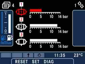
M54.00-1750-71 The supply pressures (0 to 14 bar) for circuits 1 (front axle or trailing axle), 2 (driven axle) and 3 (auxiliary consumers) are displayed. The white areas of the scales highlight the acceptable pressure range during normal vehicle operation. By contrast, the grey areas of the scales indicate critical pressure values. A malfunction alert is issued whenever a pressure reaches a critical value. The pressure value can be viewed in the monitoring menu after the malfunction alert has been acknowledged. The symbol and the bar graph for the compressed-air circuit concerned are coloured yellow or red, depending on how critical the malfunction alert is.
Danger.
In the event of a red warning level malfunction, the bus must be stopped immediately (traffic conditions permitting) and an EvoBus Service Partner must be notified.
Caution:
In the event of a yellow warning level malfunction, it is permissible to drive on carefully but the bus should be checked by an EvoBus Service Partner at the earliest opportunity.
“Engine” submenu
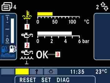
M54.00-1721-71 The “Engine” submenu displays coolant temperature (1), engine oil pressure (2) (0 to 6 bar) and engine oil level (3). The white areas of the scales indicate the values to be expected during normal operation. If a critical value is reached, the associated symbol and bar graph turn yellow or red.
Danger.
In the event of a red warning level malfunction, the bus must be stopped immediately (traffic conditions permitting) and an EvoBus Service Partner must be notified.
Caution:
In the event of a yellow warning level malfunction, it is permissible to drive on carefully but the bus should be checked by an EvoBus Service Partner at the earliest opportunity.
Note:
The coolant temperature should be approximately 85 °C when the engine has warmed up to normal operating temperature. The engine oil pressure should be higher than 0.5 bar at idling speed and higher than 2 bar when the bus is being driven. A negative value (-) for the engine oil level indicates that the oil level needs to be topped up (refer to the “Practical advice” section of the Operating Instructions - Engine oil level display)
Driver's area controls
Menu structure
“Voltage” submenu
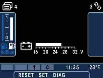
M54.00-1732-71 The on-board voltage is displayed in this separate submenu.
Note:
The battery voltage display should show 25 - 28 V when the engine is running. If this is not the case you should contact an EvoBus Service Partner at the earliest opportunity.
Driver's area controls
Menu structure
“Betriebsmeldungen” (Operating notifications) submenu
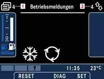
M54.00-1704-71 Selected, important operating notifications are displayed in their own submenu rather than in the lower permanent display field. These notifications do not necessarily need to be brought to the driver's attention. If, however, the driver would like to view information about the condition of a specific vehicle system, it is possible for the driver to call up these operating notifications by selecting this menu.
Note:
The majority of the operating notifications in this submenu relate to the heating, ventilation and air-conditioning system.
5. “Events” main menu
In the “Events” main menu, the driver is able to view the event notifications that are currently present. As each event notification constitutes a separate submenu and the quantity of event notifications is ever changing, the submenus in this main menu are not individually numbered.
“Overview” submenu
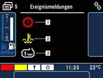
M54.00-1744-71 The overview presents a collection of symbols, one for each event notification. The symbol colour indicates the urgency of the notifications, i.e. red alerts (1) are represented by red symbols and yellow alerts (2) by yellow symbols. Other event notifications (3) are represented by white symbols. Each notification category is designated one line containing a total of four symbol positions.