26 minute read
0. GeneralInformation


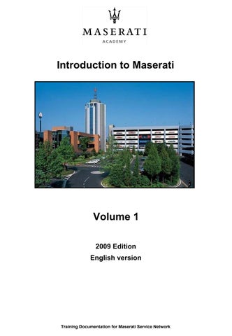
The new Maserati GranTurismo, introduced at the Geneva motor show in March 2007, is a technical spin-off of the QuattroporteAutomatic and reflects its power, stability and comfort features.
Its authentic and unmistakably Maserati style transmits an imageof power and elegance. Pininfarinahas tailor-made the sleek and sensual bodywork, developed around the GranTurismoproject idea: create a sports car yet with plenty of space to suit one and all. From the large oval mouth that envelops the radiator grille right through to the rear, the bodywork sits on the mechanics like a tight-fitting dress on sinuous hips. The resulting powerful, trim and elegant shape arouses an emotion that only a timeless design can give. The elegant design of the interior, made warm and cosy by the quality materials and handmade finishes, embraces the passengers in a bright, comfortable and sporty atmosphere.
The new Maserati GranTurismosprings from the experience gained with the Quattroporte in the luxury car sector, and provides a unique implementation of those concepts that have made the model an unchallenged international success.
The new Maserati GranTurismohas the following features in common with the Quattroporte:
•the mechanical configuration designed to provide an emotional driving experience
•meticulous care in the choice of materials and equipment, aimed at creating a sophisticated and comfortable ambience.
•a complete range of customisation options so that the customers can express their own personality and satisfy their needs.
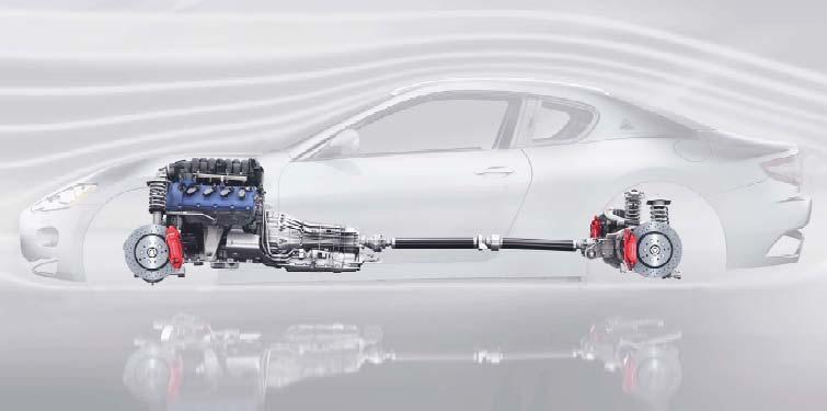
Dimensions, capacitiesand weights
Length: 4,881 mm
Width: 1,847 mm
Width: 2,056 mm
Height: 1,353 mm
Wheelbase: 2,942 mm
Front track: 1,586 mm
Rear track: 1,590 mm
Front overhang: 873 mm
Rear overhang: 1,066 mm
Luggage compartment capacity: 260 l
Fuel tank capacity: 86 l
Dry weight (UE version): 1,780 kg
Unladenweight (UE version): 1,880 kg
Kerb weight with driver (UE version): 1,955 kg
Maximum permitted weight: 2,180 kg
Technically permitted weight: 2,250 kg
Kerb weight distribution: 49% Front; 51% Rear
Vehicleperformances
Top speed: 285 km/h (at 7050 RPM in 5°gear)
Acceleration from 0 to 100 km/h: 5.2 s
Acceleration from 0 to 400 metres: 13.4 s
Acceleration from 0 to 1000 metres: 23.9 s (output speed 225 km/h)
Pickup from 80 to 120 km/h: 3.7 s
Stopping distance from 100 km/h to 0: 35 m
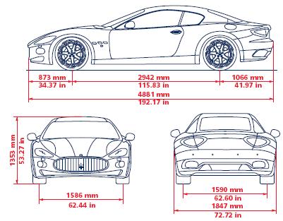
Weight distribution is one of the key reasons behind the stability and balance of the vehicle, which also enhances the safety features perceived whiledriving. The configuration designed for the GranTurismo was obtained by moving the engine assembly to behind the front axle which, in everyday driving, translates into smooth and predictable vehicle behaviour. This not only enhances comfort and handling but also maximises traction during acceleration and road holding. With respect to the QuattroporteAutomatic, overall vehicle performances have been improved, while fuel consumption has decreased (3%), notwithstanding the mechanical base is identical. This is thanks to the lower vehicle weight, improved aerodynamic efficiency (Cx: 0.33), specific software for engine and gearbox control, and aslightly shorter final drive ratio of the differential.
Fuel consumption and emissions (2004/3/EC directive)
City cycle: 21.58 (l/100 km)
Motorway cycle: 10.02 (l/100 km)
Average fuel consumption: 14.31 (l/100 km)
CO²emissions (average): 335.0 (g/km)
Scheduled maintenance
The scheduled maintenance program for the Maserati GranTurismois identical to the one for the Maserati QuattroporteAutomatic.
Towing the vehicle
If you need to tow the vehicle, observe the following recommendations: if possible, have the vehicle transported on a vehicle equipped with loading platform and specific for roadside assistance and recovery. If this is not possible: tow the vehicle lifting the driving wheels (the rear ones). If this is not possible: tow the vehicle for a distance of less than 100 km at a speed below 60 km/h. Tow the vehicle using the towing hook found in the toolkit. Screw the towing hook down tightly in its seat, on the lower, right-hand side of the front bumper. In addition, for towing you must engage Neutral by moving the gearshift lever to position N. Do not extract the key, as the steering wheel will lock automatically and you will be unable to steer the wheels. WARNING: If you have to tow the vehicle with 2 wheels raised, ensure that the ignition key is in the STOP position. Otherwise, with the MSP activated, the relative electronic control unit stores a malfunction and the warning light on both the instrument panel and the display will come on; the vehicle will have to be taken to the Maserati Service Network to have the malfunction corrected.
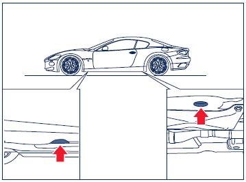
Lifting and jacking
Usethe theindicatedpointsonlyforlifting or jackingof the vehicle.
1. Engine
The Maserati GranTurismouses a 4.2 90°V8 wet sump engine, code named F136UD. This engine is basically the identical to the engine used by theQuattroporteAutomatic (F136UC). Modifications were made only to the controlling sofware(different mapping), which gives the engine a slightly higher power output for the GranTurismoand more allert reactions to the commands of the accelerator pedal. This to enhance the dynamic characteristics of the vehicle.
The basic technical solutions of this new engine has been designed to obtain high specific power and to rapidly increase and decrease of the RPM, which is typical of competition engines, yet always with a watchful eye on fuel consumption, driving smoothness and silent operation.
The specific tuning of the V8 engine of the Maserati GranTurismo, unlike that of the engines used in the automatic versions of the Quattroporte, was aimed at improving the response to the accelerator commands (+20% in SPORT mode compared to the QuattroporteAutomatic). In this configuration, the engine reaches its maximum 405 HP at 7100 RPM (specific power of 96.4 HP/litre) and the maximum torque of 460 Nm at 4750 RPM, 75% of which is already available at 2500 RPM.
See chapter 3 “Mechanical Components”for more detailed information about this engine.
Engineperformance curves:
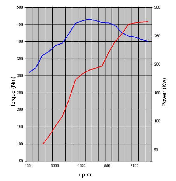
Max power: 297kW (405 HP) at 7100 rpm
Maximumtorque: 460 Nm(47Kgm) at 4750 rpm
Enginecontrol system:
The enginecontrol system and itsvariuoscomponentsof the GranTurismoisidenticalto the system of the Quattroporte withautomatictransmission. The usedenginecontrol system isBosch Motronic7.1.1; calibrationsoftware ishoweverspecificforthe GranTurismo.
On the nextpagesare onlydescribedthe systemsor partswhichhavebeenmodifiedfor the GranTurismo.
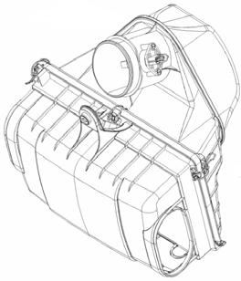
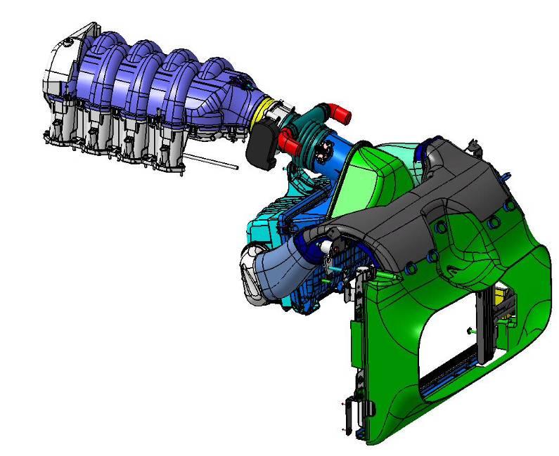
Air intake system:
The air intakesystem of the GranTurismohasthe samecharacteristicsasthe Quattroporte Automatic. The shapeof the front air ducthasbeenmodified and isthusspecificforthe GranTurismo.
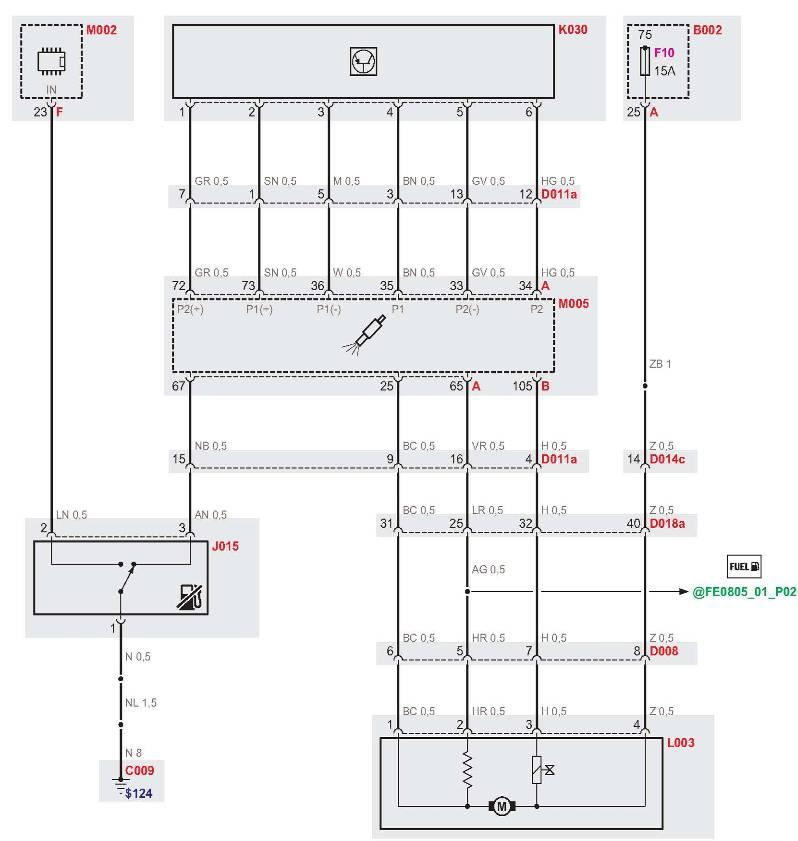
Fuel system:
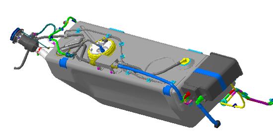
The fueland anti-evaporative system usedin the Maserati GranTurismohasthe same characteristicsasthe system usedin the Quattroporte.
Inertiaswitch:
The opertionlogicand the location of the inertiaswitchin the GranTurismoisidenticaltothe Quattroporte. The differenceliesin the factthatthe inertiaswitchisat one side nowconnectedtothe body computer (NBC). The body computer willactivate the hazardlightsand the interior lightingand willunlockthe doorsin case a collisionisdetected.
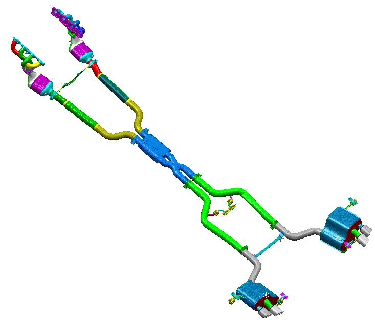
Exhaust system:
The exhaustsystem of the Maserati GranTurismois derivedfromthe system used in the Quattroporte Automaticand hasthe same characteristics. The shapeof the system hasbeenmodifiedtofitthe GranTurismo’s floorplan. Tailpipesare specific.
3. Transmission
The automatic transmission of the Maserati GranTurismohas been engineered to offer the best possible compromise between performance, driving comfort and fuel economy. It consists of the following components:
ZF 6HP26 automatic 6-speed gearbox: hydraulic gearbox with torque converter, lock-up clutch and integrated control unit (Mechatronic). Various driving modes are offered: fully automatic gearchangein normal, sport or ice mode, or manual sequential gear selection by use of the gearshift lever or gearshift paddles at the steering wheel. This gearbox is mechanically identical to the one used in the QuattroporteAutomatic. The controlling software is specific for the Maserati GranTurismoto enhance the sporty character of the vehicle (faster gearshifting).
Composed transmission shaft: the transmission shaft is composed of a front and rear part and uses three homokineticjoints. This solution was chosen because of a slight desaxationbetween the gearbox output shaft and the differential input shaft, both in the horizontal and in the vertical surface. The transmission shaft is sorter as the one used in the QuattroporteAutomatic due to the sorter wheelbase. Note: the transmission shaft requires a balancing procedure after the removal of transmission components (gearbox, transmission shaft, differential). This balancing procedure is identical for GranTurismoand QuattroporteAutomatic.
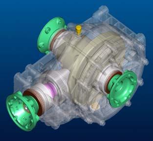
Grazianolimited slip differential: with respect to the differential of the Quattroporte Automatic, the final drive ratio has been changed. This was doneto improve performances and reduce differential noise.
Note: see chapter 3 “Mechanical Components”for more detailed information on the individual transmission components.
Adaptive gearbox strategy
By enhancing and synchronising the transmission control with other systems in the vehicle (e.g. engine, braking system, driving wheels and steering wheel)a series of signals are made available: these provide a description of the driving condition in real-time. After applying longitudinal or lateral acceleration, the ECU activates(through acquisition of signals such as engine speed and torque, oil temperature, accelerator position and movement and the rotating speed of the individual wheels) implementation of additional functions of the electronic transmission control. Based on this information, the transmission control is capable of recognising whether the vehicle is in a curve and whether the driver is braking or wishes to accelerate. By means of these signals, it is possible to draw conclusions relating to the actual vehicle loadand the topography of the road (uphill or downhill) which can then be applied to the transmission function. This system is known as automatic transmission with adaptive transmission control. It is capable of recognising the driver’s intentions, recording the driving style and consequently adapting the gear selection. Manual operation is therefore not necessary. ZF GetriebeGmbH and Robert Bosch GmbH have worked together with Maserati to produce new software for the electronic transmission control, which contains some very useful functions. The Adaptive Shift Strategy (ASIS) is based ona few important factors. Gear selection depends on the gradient of the slope while driving. The novelty is represented by the capability of continuously adapting the gearshifts to the individual driving styles which may vary infinitely from racing-style (dynamic) to extremely “economic”driving.
All the functions and their operating modes are described and represented in this brief description of ASIS. Examples of signals sent by other systems in the vehicle are given together with the evaluation these systems provide for electronic transmission control.
Lateral acceleration: The transmission ‘learns’the driver’s style and assigns a theoretical count system to certain driving scenarios. When it recognises anacceleration action, including after long periods of regular driving, it increases the number of counts for the driver until reaching the maximum level in approximately 10 seconds. The resulting counts for the driver and the time it takes to reach this level dependson the lateral acceleration level.
Longitudinal acceleration: The longitudinal acceleration is evaluated mainly to allow a decrease in counts when the driving style is constant and no other information is available (pick-up or lateral acceleration). When the driver brakes, the count system is stopped.
Calculation of the road gradient: The road gradient is calculated by comparing the actual acceleration of the vehicle with the acceleration the vehicle would have when driving on a thoroughly level road. Acceleration on a level road is calculated based on the vehicle weight and the actual torque delivered by the transmission. The ASIS system distinguishes 5 different categories of road gradient, each of which is associated with a gearshift map. The five conditions are: downhill, level, and three different uphill gradients.
Auto Normal mode
Normal driving style and reduced consumption. In the case of a driving style watchful of consumption and with reduced acceleration levels (longitudinal and lateral) the gearshift programmes are adjusted in such a way as to obtain maximum cruising comfort. In order to reduce vibrations and acoustic feedback of the engine to a minimum, upshiftingmust be performed as quickly as possible. Downshifting during pedal release or downhill driving (0% pedal depression) occur at 1000 RPM. Downshifting following the action on the accelerator and/or brake pedal is less aggressive than inthe other modes.
Racing-style driving:
When a more racing-style driving is detected in Auto Normal mode, upshiftingwith reduced pressure on the pedal occurs at a higher engine speed. In this way, the gearbox and engine have a greater reserve of power without having to downshift. Anticipation of downshifting during braking considerably increases, so that the correct gear is engaged before entering a curve.
Auto Sport Mode
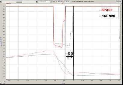
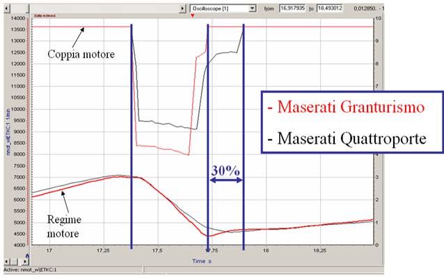
Generally, when using Sport mode, gearshiftingoccurs at much higher RPM and, at the same time, as a result of the fuel cut-off, gearshiftingis faster than in Normal mode with a reduction of up to 40% in gearshift times. This difference is very evident when the accelerator pedal is not fully depressed (i.e. pedal at 40%). The fuel cut-off technique designed for the Maserati GranTurismo(see the image that illustrates gear engagement from second to third gear at 7000RPM with accelerator pedal depressed by 40%) permits reducing the time necessary to cut the torque to the engine, shift gears and provide power once again. Normal drivingstyle and reduced consumption.
When using Sport mode in normal driving conditions without high lateral acceleration, the gearbox management software as a rule uses a lower gear than would be used in similar conditions in Auto Normal mode. Without operating the accelerator/brake pedal, downshifting is requested at about 1500 RPM. This makes the gearbox response much more racing-like without significantly affecting driving comfort. When driving on a motorway, 6th gear is engaged at a speed of 125 km/h. Racing-style driving:
In order to achieve the best reactivity, the gearshift maps are set to very high engine speeds. With reduced pressure on the pedal or with the pedal at 0%, upshiftingoccurs at approximately 4000 RPM. Downshifting, following an action on thebrake pedal, is adjusted in such a way that the gear is engaged before going into a curve, so that the driver has optimal control and an adequate reserve of power to come out of the curve. This mode is therefore specifically designed for driving at high speeds or for very difficult road conditions.
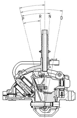
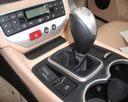
The automatic electronically-controlled gearbox has 6 forward gears and one reverse gear. In addition to automatic gear selection, the gears can also be selected manually.
The lever position is shown on the gear display by the illumination of the corresponding letter. This letter is also shown on the instrument panel display. The engine can only be started when the gearshift lever is in P or N.
WARNING: After starting the engine and setting off, do not depress the accelerator pedal before and while shifting the gearshift lever. This is particularly important when the engine is cold.
Shift-Lock
This safety system allows you to shift from P (PARK) to another position only if the brake pedal is depressed. This prevents the vehicle from involuntarily jumping forward or backward.
Key-Lock
After turning off the engine with the gearshift lever in a position different from “P”, the key can be extracted within a maximum time of 30 seconds. When this time has elapsed, the key can no longer be removed from the ignition block. To remove the key, you must turn it to ON and then back to OFF.
WARNING: In the case of an emergency, (e.g., breakdowns, dead battery etc.) the ignition key can be removed even if the gearshift lever is not in P. To do this, turn the key to STOP, press the button A on the gearshift lever and at the same time remove the key.
CAUTION!
When parking on steep slopes, it is recommended to shift the lever to PARK before leaving the vehicle (whether the engine is running or not). This is recommended since the EPB system installed in the vehicle is capable of ensuring that the vehicle is properly parked and stationary when fully laden only on a gradient up to 20%
Selecting automatic or sequential manual operating mode: The gearbox can be used both in fully automatic (position D) andin sequential manual (positions + or -) mode.
The operating modes can be activated through the following selections:
•D automatic gearshifting(AUTO)
•M (+ / -) Sequential manual gearshifting(MANUAL)
The lever can always be shifted between these two positions evenif the vehicle is moving and without depressing the brake pedal. The lever can continuously be shifted between D and M.
If automatic gearshift mode is selected, the word AUTO and the letter D will be shown on the instrument panel display, while for sequential manual gearshifting, the word MANUAL and the gear engaged will be shown.
Automatic selection operating mode
Select the D (drive) position when you wish to use all the automatic gearshift functions. With the vehicle stationary and the brake pedal depressed, shiftthe gearshift lever to D; if the gearshift lever is in P or R, also press the button A on thelever knob. When the function is set, the letter D illuminates on the gear display and on the instrument panel. With this function active, the ECU controls automatic engagementof the six gears. The gears will be engaged in relation to the travelling speed, engine RPM, accelerator position, speed with which the pedal is depressed, as well as the travelling conditions (uphill, downhill, curves).
The system is programmed to classify all driving styles related to the above mentioned parameters, matching them to ten different vehicle settings which go from extremely comfortable and fuel-economy driving to full racing-style driving. The setting is selected automatically.
Kick-down strategy
This strategy is activated by rapidly and fully depressing the accelerator pedal, which causes engagement of a lower gear than the current one; this function assists the driver when maximum acceleration is required. When the pedal is released, the best gear in relation to the vehicle speed and the position of the accelerator pedal is automatically engaged. The kick-down strategy can be activated only when automatic operation has been set, with the gearshift lever in position D.
Manual selection operating mode
Push the gearschiftlever to the left from the D position to select the manual mode. To engage the gears, move the gearshift lever to the following two positions:
+ UP to engage a higher gear
- DOWN to engage a lower gear.
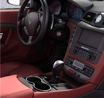
The Maserati GranTurismohas gearshift paddles behind the steering wheel as a standard feature. In sequential manual operating mode, upshiftingand downshifting can be controlled not only with the gearshift lever but also with the two levers positioned behind the steering wheel.
Also in automatic gearbox operation with the gearshift lever positioned in D (drive), you can request a gear different from the current one by activating one of the levers. This action will temporarily switch the system to sequential manual operation. If you then keep to a constant driving style (low longitudinal and lateral acceleration), the gearbox automatically switches back to automatic operation.
WARNING: Even if manual gearshiftingmode has been activated, some functions are still controlled automatically. When the engine is overrevvingor underrevving, the system automatically engages a higher or lower gear.
WARNING: If you request a gearshift in conditions where the engine is overrevvingor underrevving, the system will not accept the command.
WARNING: The electronic control unit is programmed to handle one gearshift at a time, therefore, fast and repeated requests will not necessarily result in a gearshift. The higher or lower gear is engaged only if the previous gearshift procedure has been completed.
Parking
When parking the vehicle, shift the lever to the P position (park). A gear device inside the gearbox will lock the driving wheels.
WARNING: To prevent accidental engagement, the gearshift lever can onlybe shifted from P to any other position when the button on the gearshift lever and the brake pedal are depressed.
WARNING: Shift the lever to position P only when the vehicle is stationary.
WARNING: Before getting out of the vehicle, check that the automatic parking brake is engaged. Shift the gearshift lever to P even when you need to get out of the vehicle for only a few seconds leaving the engine running.
WARNING: If you turn off the engine with the gearshift lever in a position different from P, an acoustic signal will sound for a few seconds. If you open the driver’s door with the gearshift lever in a position different from P, an acoustic signal will sound for a few seconds.
Strategies for downhill driving
When the DRIVE mode is selected and the accelerator pedal is released, the gearbox system detects that the vehicle is moving downhill and deactivates upshifting. When the accelerator pedal is depressed, upshiftingis reactivated, however, with a delay of a few seconds.
When the brake pedal is depressed, the gearbox system downshiftsto provide enhanced engine braking power. In other words, when dr iving downhill, thegearbox system operates so as to avoid upshiftingand shifting gears when the accelerator pedal is released, and delays gear engagement by a few seconds when the accelerator pedal is depressed. In addition, when the brakes are applied, it engages the lowest gear in order to provide enhanced engine braking power. This strategy is aimed at making downhill driving safer.
Strategies in curves
The gearbox system detects when the vehicle is in a curve through the lateral acceleration and the steering angle. Detecting the DRIVE mode, the system deactivates both upshifting and downshifting until the vehicle comes out of the curve. In particularly tight uphill curves the system downshifts. Gearshiftingis reactivated when the vehicle comes out of the curve at a distance that varies depending on the vehicle speed.
Hot-mode strategy
In the event that the engine oil or coolant temperature or both are too high, the gearbox system reduces the maximum engine speed to 4000 RPM. For this reason, upshiftingwill occur at this limit.
This strategy does not apply to downhill driving, so as to always have the efficiency of engine braking together with the standard braking system.
Acoustic signals
If you turn off the engine with the gearshift lever in a position different from P, an acoustic signal will sound for a few seconds.
If you open the driver’s door with the gearshift lever in a position different from P, an acoustic signal will sound for a few seconds.
With the lever in R, the system emits an acoustic signal for a few seconds to warn anyone in the vicinity that you are about to reverse.
Gearshift lever release in emergency conditions
In the event of failure of the electrical power supply system with resulting dead battery, the vehicle may only be moved after the gearshift lever has been released from the P position and moved to the N position. When there is no power, the lever can only be released using the emergency procedure.
•Remove the cover G in front of the gearshift lever.
•Using the screwdriver contained in the toolkit, push on the release mechanism working through the hole and at the same time shift the gearshift lever to N.
•The gearshift lever has now been released.
NOTE: In order to tow the vehicle, the emergency release procedure of the EPB system must be performed.
Low gearbox oil level
The red icon indicates that the gearbox oil level is too low. Ifthe warning light comes on, stop the vehicle. The gearbox oil level must be checked. Note: the gearbox does not contain an oil level sensor or switch. The gearbox oil level is a calculated estimation made by the electronic control unit.
Automatic gearbox failure
Depending on the different related messages, the symbol may indicate:
-a gearbox failure (error code stored)
-a too high actual temperature of the gearbox oil (no error code)
Gearbox failure
This message, highlighted in red, indicates a gearbox system failure, therefore, if you are travelling, the ECU that controls the device sets an emergency program. In these conditions, we recommended that you stop the vehicle and turn off the engine for at least one minute. When restarting the engine, the autodiagnosticsystem may cancel the malfunction, which will in any case be recorded by the ECU.
In failure conditions, the gearshift lever can always be shiftedto R, N, D and P. When shifting to the latter position, only a few gears will be available, depending on the malfunction found.
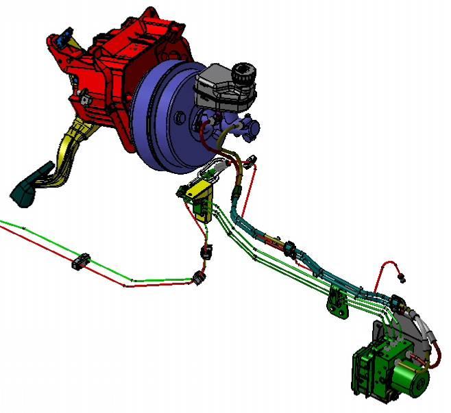
4. BrakingSystem
System components
•Brake servo 8+9“Ø
•Tandem brake master cylinder 15/16" Stroke 18+18mm
•Servo control ratio 13.5
•Self-ventilated front discs 330x32mm
•Self-ventilated rear discs 330x28mm with new brake calipers
•Parking brake with electric activation
•ABS/ESP Bosch 8.0
The Brembobraking system of the Maserati GranTurismois equipped with 4 ventilated discs on the front and rear wheels (front 330 mm Øx 32 mm, rear 330 mm Øx 28 mm) with 4-piston calipers.
Brake performance:
Stopping distance: from 100 to km/h: 35 m
Maximum deceleration: 1.24 g
From a safety point of view, the vehicle is equipped with ABS, which prevents the wheels from locking during braking, and EBD, which provides optimal brake force distribution between the front and the rear; both are integrated in the MSP system (Maserati Stability Program). MSP contains further electronic stability control (ESP), traction control (ASR) and engine brake torque control (MSR).
To help the driver during uphill starting, the Maserati GranTurismois fitted with the “Hill Holder”device which, in the case of sloped roads, immobilises the vehicle for a few seconds to allow the driver to move his foot from the brake pedal to the accelerator pedal without the vehicle rolling back.
The standard brake calipershave black finishing; on request, they can be supplied in five different colours: red, yellow, titanium, blue and silver. The Maserati name is black (for the red, yellow and silver calipers), white (for the black and blue calipers) and red (for the titanium calipers).
Electric Parking Brake (EPB)
The Maserati GranTurismoisstandard fittedwithanelectricparking brake(EPB). The system isidenticaltothe one usedin the Quattroporte Automatic.
The EPB system is composed of:
• EPB actuator (cable puller) with integrated ECU
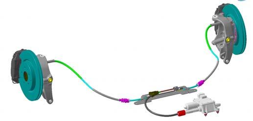
• Primary cable
• Equalizer / divider
• Secondary cables (LH + RH)
• Drum parking brakes, integrated in the rear brake discs.
• Parking brake command switch
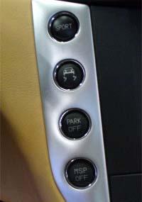
•“Park off” button
• Emergency release tool (integrated in the toolkit)
System operationand variousfunctionsare identicaltothe Quattroporte Automatic system. SeeQuattroporte formore details.
Note: Al GranTurismovehiclesare fittedwiththe PRE RELEASE function.
Maserati StabilityProgramm(MSP)
The Maserati QuattroporteAutomatic has a new stability control system integrated in the Bosch ESP 8 ECU. The dynamic performance of the Maserati GranTurismois supported by the Maserati Stability Program (MSP), specifically developed by the Trident engineers to provide greater safety and optimise the dynamic performance of the vehicle. The system is based on a set of sensors capable of detecting any vehicle failure with respect to ideal dynamic performance. It acts on the brakes and engine to stabilise their setup and restore proper performance. The Maserati Stability Program (MSP)performs the following functions: if the system detects a tendency to side skidding, it reduces the torque; it activates the brakes and stabilises the vehicle in just a few milliseconds (ESP); it prevents the wheels from locking during braking (ABS); it distributes the brake force between the front and rear axle,preventing the rear wheels from locking (EBD);
− it prevents slipping of the driving wheels, improving traction in low-grip conditions (ASR);
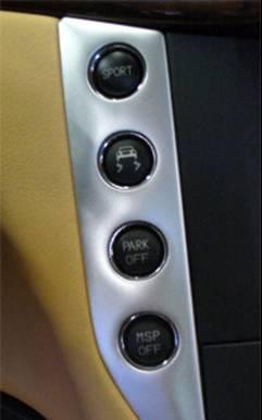
SPORT mode
Also for what concerns the MSP, the driver can choose Sport mode: in normal conditions, the system acts both on the engine torque and the brakes; when the SPORT button is pressed, the stability program is less "invasive" and permits enhanced racingstyle driving without however affecting safety. In fact, the operating threshold is raised and the system mainly operates on the brakes without cutting power to the engine.
MSP OFF mode
Pressing the “MSP OFF”button you can deactivate all the driving control systems (ESP, MSR and ASR), leaving only the ABS and EBD systems active. In emergency conditions, depress the brake pedal to reactivate all the driving control functions. If The vehicle will perform without any safety system and the driver will have to rely only on the vehicle and his driving skills for particularly exciting driving. Of course, it is advisable to use the “MSP OFF”mode only on dry roads and on tracks closed to traffic. Even if the control system is deactivated, the Anti-LockBraking System (ABS) will remain active to prevent wheel locking or skidding. In order to prevent unstable driving conditions, the MSP system may request the gearbox system to disable automatic gearshifting. This request is processed by the system which, depending on the gear engaged and the engine RPM, will evaluate the appropriate gearshift or temporarily deactivate this feature.
ICEmode
This mode can be used on particularly slippery road surfaces (e.g., snow, ice) and it is activated/deactivated by pressing the button on the NIT. The word ICE will illuminate on the instrument panel display. In “Low-grip" mode the system uses 2nd instead of 1st gear. This means that when you start from a stationary position with the engine running -both in automatic mode (gearshift lever in D) and manual mode (gearshift lever in M) -the vehicle will start in 2nd gear. When sequential manual mode is selected with 2nd gear engaged, a downshift request will be ignored. When sequential manual mode is selected with 2nd gear engaged, a downshift request will be ignored. While driving, the system automatically switches to the upper gear if the engine reaches the pre-established speed rate (3,000 RPM). “Low-grip" mode has priority over SPORT mode and assists the MSP system. If “ICE”mode is activated when “SPORT”mode is active, during the transition stage it may happen that both the “ICE”and the “SPORT” messages are present on the CAN line. In this case, the system will give priority to the “ICE”message, immediately showing it on the display.
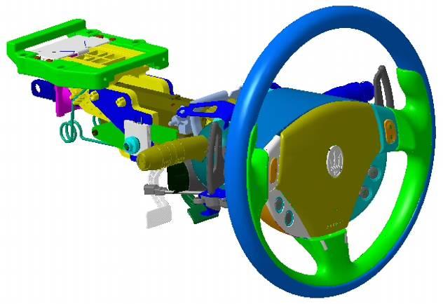
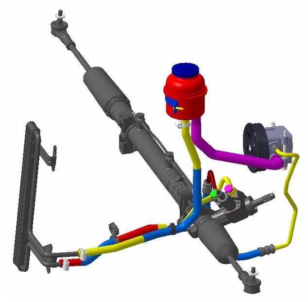
5. DrivingControls
The standard steering column has manual adjustment for height and depth. Instead of the steering column with manual adjustment, you can request the version with electrical adjustment in combination with the comfort pack for the seats (this includes storage of the settings and heating).
The steering rack (TRW) and vehicle speed sensitive power steering are similar to the one used in the Quattroporte. The steering ratio has been changed with respect to the Quattroporte(more direct) to offer a more dynamic vehicle control. Steering diameter (from pavement to pavement): 10.7 m
6. Suspensionsand Wheels Wheels
In the standard configuration, the Maserati GranTurismois equipped with 19”aluminium wheel rims with different-sized front and rear tyres: for better power discharge to the ground, the rear tyres have a wider tread than the front ones.
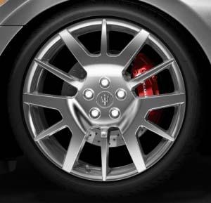
The 19”wheel rims are in light alloy; front 8.5J x 19, profile H2; rear 10.5J x 19, profile H2; Front tyres 245/40 R19, rear tyres 285/40 R19.
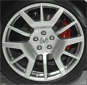
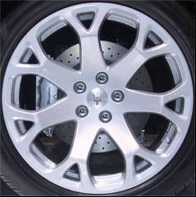
A racing-style 20”version is available, which, although slightly reducing comfort, increases handling and response to steering movements, thanks to the effect of the smaller drift angle. The look is inspired by that of the Birdcage 75°wheels and further underlines the power of its mechanics.
Optional: 20" light alloy wheel rims; front 8.5J x 20, profile H2; rear 10.5J x 20, profile H2; Front tyres 245/35 R20, rear tyres 285/35 R20.
Both types are available with Ball-Polished treatment and in mercury grey:
− The ball-polished treatment emphasises the mechanical features at the same time gives a brilliant effect even if not as eye-catching as the chrome-plated wheels.
The dark mercury grey further highlights the racing-like character of the GranTurismo.
Tyre pressure monitoring system (optional)
TRIP button : displays the “Tyre pressure”information for 10 seconds
Information displayed :
-System temporarily inactive (for example: external radio interference)
-System not calibrated (for example: a tyre has been replaced )
-System failure
-System not active (if it is disabled by the diagnostic system)
-Low pressure or puncture of the LH front, RH front, LH rear and RH rear tyres
-Low pressure or puncture in unidentified tyre
Note: If the system is not calibrated (for example: a tyre has been replaced) calibrate the system by pressing the button on the front ceiling light (from 4 to 10 sec.). The completion of the calibration procedure is indicated on the instrument panel.
System calibration
After replacing or inflating one or more tyres, the system must be calibrated once again. To calibrate the system, press and hold button A, located on the inside roof, for a time ranging between 4 and 10 seconds. The system takes a maximum of 20 minutes to complete the calibration procedure with the vehicle in motion. Agreen symbol will appear on the display together with the message "Calibration started”. If the user recalls the information page showing the pressure levels of each tyre, dashes “–.–”will be viewed in the place of the values.
You can access the information screen page that shows the pressure values of each tyre by repeatedly pressing the “Mode”button B
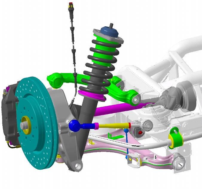
Suspensions
The chassis of the Maserati GranTurismois fitted with overlapping-triangle front and rear suspension with forged aluminium hub carrier and arms, with the aim of reducing the unsprungweights of the vehicle.
As an optional, the Maserati GranTurismocan come equipped with aluminium gas shock absorbers with Skyhook system for automatic and continuous damping adjustment. This technology is used to assure optimal comfort levels with any road condition, without affecting performance and the racing-style character of the vehicle.
The Skyhook system acts by means of acceleration sensors which record the movements of each wheel and the bodywork. The ECU processes the information received, analyses the driving style and the road conditions and immediately adjusts the shock absorbers by acting on the proportional valve of each of them.
In the case of the fixed calibration system, the suspension set-up is optimised for handling:
•The standard suspension has been designed for those customers who prefer good handling over driving comfort.
•The standard suspension provides a vehicle set-up which is quite similar to that used with the Skyhook system in Sport mode.
•The Skyhook suspension offers superior driving comfort with respect to the standard suspension.
Skyhooklayout
Front suspensions
•Articulated quadrilateral independent wheel suspension with double oscillating triangle
•Anti-dive and anti-squad geometry
•Forged aluminium levers, aluminium hub carrier
•25 mm øarticulated stabilizer bar on ball joints
•Optional Skyhook variable-damping aluminium hydraulic shock absorbers
•Suspension mounted on a new separate frame rigidly connected to the bodywork
Rearsuspensions
•Articulated quadrilateral rear independent wheel suspension with double oscillating triangle

•Anti-dive and anti-squat geometry
•Forged aluminium levers, aluminium hub carrier
•24 mm øarticulated stabilizer bar
•on ball joints
•Optional Skyhook variable-damping aluminium hydraulic shock absorbers
•Suspension mounted on a new separate frame rigidly connected to the bodywork
Wheel alignment
Front Camber : -0.30°±0°10’on each wheel
Caster : 3.30°±0°10’on each wheel
Total toe-in: -2,1 ±0.4mm (1,05 mm opening on each wheel)
Rear Camber :-1.30°±0°10’on each wheel
Total toe-in: 4.2 ±0.4mm(2,1 mm closing on each wheel)
Caution Caution
The characteristic angles must be adjusted during “static load” configuration, that is, with all the fluid tanks filled, the fuel tank full (90 litres) and 75 kg on both front seats.
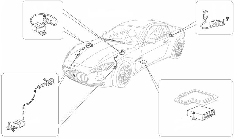
7. Safety components
The vehicle is equipped with 6 airbags (2 front and 4 lateral ones) and electronicallyoperated pretensionersfor all of the seat belts.
The system components are the following:
1) Electronic control unit
2) Passenger's front airbag
3) Air bag deactivation switch passenger's side
4) Passenger's front seat belt pretensioner
5)Passenger's side bag
6) Satellite crash sensor on passenger side
7) Passenger-side door-mounted airbag
8) Driver-side door-mounted airbag
9) Driver's side bag
10) Satellite collision sensor on driver side
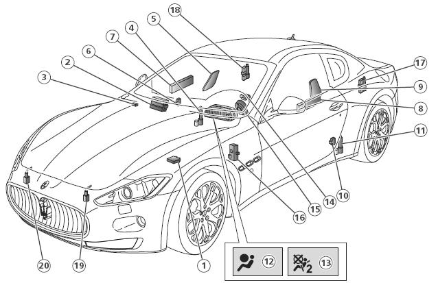
11) Passenger's front seat belt pretensioner
12) Airbag system failure warning light
13) Passenger’s airbag deactivation warning light
14) Driver's front airbag
15) Clock Spring
16) Diagnostics socket
17) Rear left-hand pretensioner
18) Rear right-hand pretensioner
19) Front left-hand Crash Zone pretensioner
20) Front left-hand Crash Zone Sensor.
If replacing the NAB or a component of the airbag system, the initialisation procedure must be performed on the new component. To perform the initialisation procedure, detach the electrical connectors for the driver's airbag, passenger's airbag and side bags positioned under the front seats.
Caution
Follow the instructions and relative safety regulations for removal and storage of the airbag modules.
Connect the SD3 diagnostics tester to the NBC diagnostic socket.
Access "CYCLE ENVIRONMENT", select the airbag node configurationcycle and continue. After entering the vehicle data, select "CONTINUE" andturn the key to ON. Wait for the checks to be completed and then follow the guided procedure, by means of which the tester will check the information available in the ECU.
Continue with the cycle until the tester prompts you to connect the driver-side airbag connectors, but without fitting the two secondary locks (safety devices for the connectors). Connect the two secondary locks, first connecting the yellow oneand then the green one. Subsequently, the page "ATTACH THE CONNECTOR THAT KEEPS THE PASSENGER AIRBAG LINE 1 IN SHORT-CIRCUIT" will be displayed.
The part number of the fake connector is 900027450. This can be ordered from the Maserati Spare Parts Department. Connect the fake connector 900027450
Wait until the next screen pages prompt you to remove the fake connector 900027450 and to attach the passenger-side airbag connector. Attach the passenger-side airbag connector. Subsequently the screen page prompting you to attachthe sidebag connectors will be displayed. Connect the sidebagconnectors.
The diagnostic tester will then perform a check of the switches for the front and rear seat belts.
Buckle the seat belts in the following order:
-Front seat, driver's side
-Rear left-hand seat
-Rear seat, passenger's side
-Front seat, passenger's side
The buckled seat belts are displayed in red.
The diagnostic tester then asks the user if the manual deactivation device for the passenger-side airbag is fitted. Reply "yes" and continue with the cycle. Perform the requested operations to check that the manual airbagdeactivation device is properly functioning.
The diagnostic tester will then prompt you to check that the airbag warning light on the instrument panel is off. Subsequently, the summary of the initialisation cycle progress appears, which should be printed and filed.
Refit all the components previously removed to access the electrical connections of the airbag system.
8. ElectricalSystemsand Devices
Electronic vehicle architecture
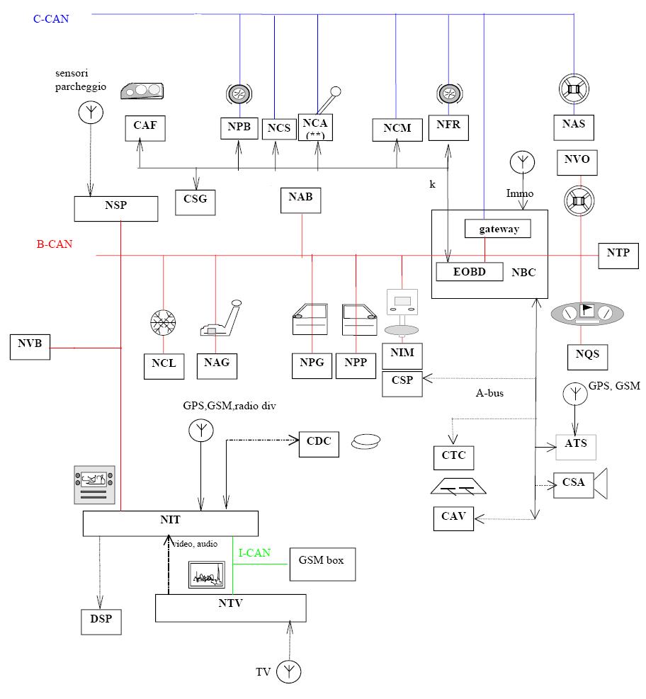
The electronic and electric functions of the various ECUsand nodes are controlled by the F.L.ORE.N.C.E system, a technology that Maserati introduced withthe Quattroporte. The use of this new system, designed for CAN communication, has allowed us to find immediate solutions as to communication, dimension, weight and cost problems. Each electronic control unit is positioned in the barycentre with respect to the functions it controls, so that the system is fully optimised.
The F.L.ORE.N.C.E. system is made up of two CAN communication networks:
• C-CAN network: dynamic control and management of the vehicle (high speed);
• B-CAN network: control of the standard bodywork functions (low speed).
The C-CAN and B-CAN networks are connected to each other by the body computer unit which is equipped with both the interfaces and hence performs the network GATEWAY function for transferring information.
The system also provides a number of serial lines used for diagnostics and other specific functions:
•K-line diagnostics for NCM / NFR / CSG / NCS / CAF
•Serial line w for immobilizer recovery
•A-BUS serial line for alarm, windscreen wiper and twilight sensor control.