12 minute read
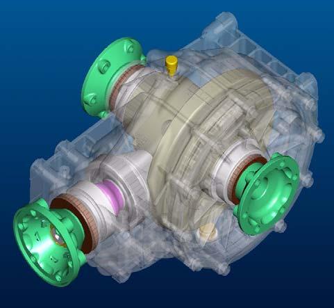
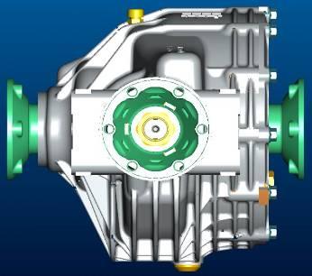
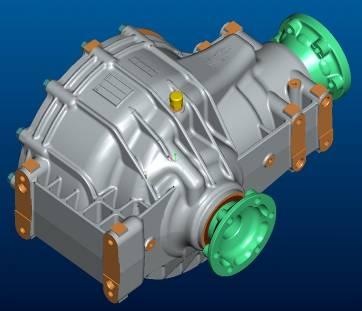
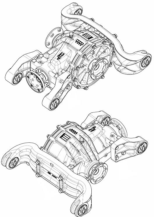
Graziano Differential


Graziano Differential
The limitedslip differentialbuiltby Graziano isusedin the Quattroporte and GranTurismoin combinationwith the ZF automatictransmission (M139GQ and M145BL)
The rear differential compensates for the different wheel movements. The configuration of this differential provides for:
•25% locking during acceleration
•45% locking during deceleration
It is fastened to the chassis by means of specific cast iron mounts
Technical Specifications
Self-locking differential , Limited Slip type
Oil type: Shell SpiraxS 75W140
Quantity: 1litre
Bevel gear pair: spiral with involutegear tooth profile
Final drive ratio for GranTurismo: 15/56
Final drive ratio for Quattroporte: 13/46
Support bearings: tapered rollers
Pinion axial clearance restored by means of a collapsible spacer
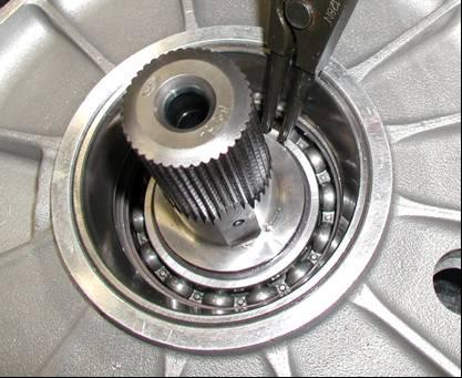
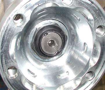
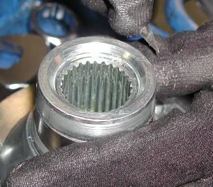
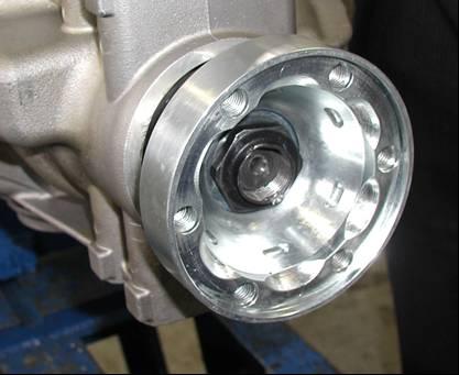
Checking the clearance between the crest and the tooth of the pinion and crown wheel:
Undo the retaining screws of the differential housing cover. Remove the axle shaft coupling flange and the relative bearing. Then turn over the cover and remove the snap ring from the inside.
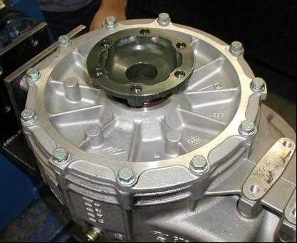
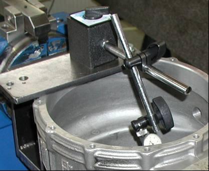
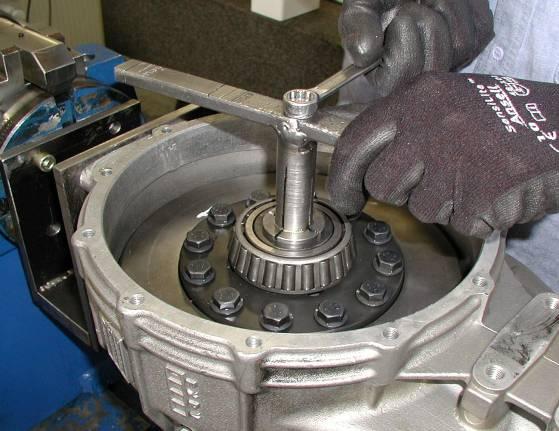
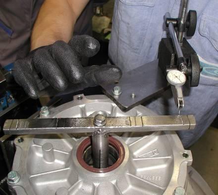
Place the cover in a press and, using a punch of suitable dimensions, remove the differential flange shaft. Fit the differential cover and temporarily secure it with three or four screws, then fit a base (1) onto it, which must be screwed onto one of the cover fittings.
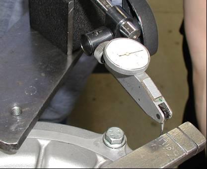
Position a dial gauge with a magnetic mount (2) on the base (1).
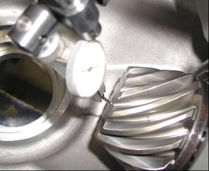
The plunger of the dial gauge must be positioned on the crown wheel diameter marking (Æ224mm), shown on the specific tool.
Check that the clearance between the pinion and the crown wheel is between 0.08 and 0.10 mm
If the value falls within the specified values, complete the assembly stages.
Remove the magnetic mount, the dial gauge and the differential cover.
Place the cover in a press and, using a punch of suitable dimensions, fit the differential flange shaft.
Fit the snap ring.
Refit the cover and tighten the differential housing cover retaining screws to a torque of 28.5 –31.5 Nm
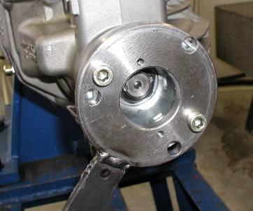
Replacing the flange O-ring on the transmission shaft side and checking the end float of the pinion
Before removing the fastening ring nut, check the residual rolling torque using a torque wrench with dial indicator on the flange nut. The inspection must be performed when the differential is removed or when the axle shafts are disconnected and without oil. With the differential crown wheel removed and without oil, the rolling torque must be equal to 1Nm ±0,5 Nm. With the complete differential, without oil and with the axle shafts disconnected, the rolling torque must be 3Nm ±1Nm. This torque must be checked once again after the flange has been tightened. Using a suitable punch, remove the two flattenedparts of the flange retaining nut
CAUTION!
The flange retaining nut must be replaced each time it is removed Remove the oil seal from its seat. Clean the O-ring residues off the flange striking surface. Then fit a new O-ring and a new oil seal using a dedicated tool.

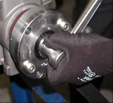
Apply a tool on the flange to lock its rotation, unscrew the nutand remove it.
CAUTION!
There must be NO end float of the pinion. The end float is eliminated by tightening the flange nut on the transmission shaft side. There is no specific tightening torque. It is recommended to apply a pre-torque and then check the end float value.
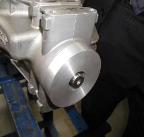
Fit the flange, apply LOCTITE 270 and screw on a new retaining nut. Apply a tool on the flange to lock its rotation. Using a specific bushing, screw on the retaining nut.
IMPORTANT:
The nut tightening torque is related to the end float read by the dial gauge on the pinion and by the residual rolling torque.
Pre-tighten the new ring nut that secures the flange. Tighten increasing the torque value torque by 5÷10 Nm at a time, after having duly checked the end float and rolling torque.
With the differential crown wheel removed and without oil, the rolling torque must be 1Nm±0.5;
With the complete differential, without oil and with the axle shafts disconnected, the rolling torque must be 3Nm ±1Nm.
When the end float is equal to zero and after checking the rolling torque, stop the tightening procedure and flatten the ring nut that secures the flange.
CAUTION!
If you have to replace the flange O-ring on the transmission shaft side (if the differential is on the bench) it is advisable to also check the clearance between the crest and the tooth of the pinion and crown wheel.
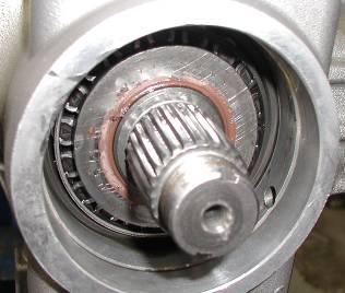
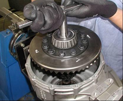
Undo the retaining screws of the differential housing cover. Remove the axle shaft coupling flange and the relative bearing. Then remove the entirecrown wheel of the selflocking unit.
After fitting the differential assembly, it is advisable to check that the clearance between the pinion and the crown wheel has not changed and that the measurement falls within the indicated values: 0.08 –0.10 mm for the 13/46 final drive (Quattroporte) and 0.08 –0.11 mm for the 15/56 final drive (GranTurismo)
Remove the magnetic mount, the dial gauge and the differential cover. Place the cover in a press and, using a punch of suitable dimensions, fit the differential flange shaft. Fit the snap ring.
Subsequently, refit the cover and tighten the differential box cover retaining screws to a torque of 28.5 –31.5 Nm
Nominal tightening torques for engine/gearbox assembly-transmission coupling:
Present Situation Of Multiplexed Architectures In The Group
Electronic architectureforsmallcars:
VENICE (VEhicle Network with Integrated Control Electronics)
•Mod. 188 (Fiat Punto)
Electronic architectureformedium cars:
VENICE PLUS or miniFLORENCE
•Mod. 937 (Alfa 147)
•Mod. 192 (Fiat Stilo)
Electronic architectureforluxurycars:
FLORENCE (Fiat Luxurycar ORiented Network Control Electronics)
•Mod. 841 (Lancia Thesis)
•Maserati M139 & M145
The Florence Can Architecture
The Florence architecture permits the exchange of information between the various ECU’s through different levels of telecommunication networks. The networks are the following:
C-CAN Network
I-CAN Network (M139 only, used for TV and data communication )
B-CAN Network
K Network (serial-line for diagnostics of the C-CAN nodes)
A-BUS Network
W-BUS Network(serial-line connecting the Body Computer and the Bosch Motronicfor recovery of the immobilizer)
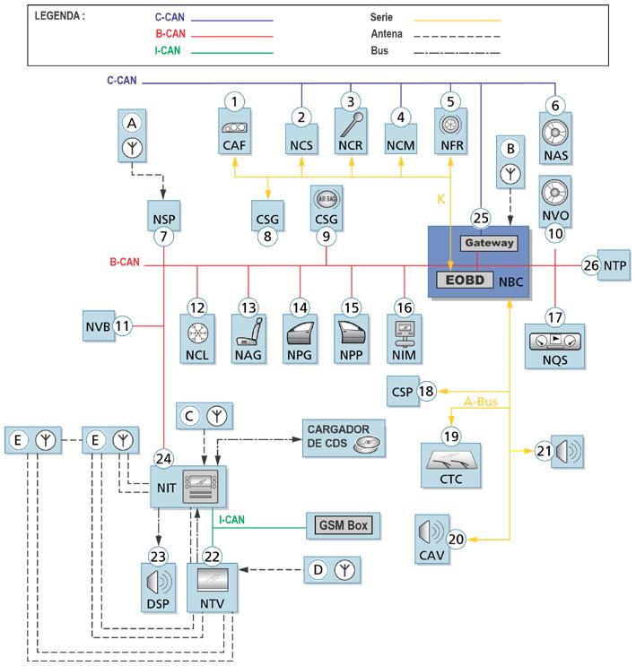
The complete structure of the FLORENCE network is illustrated bythe following figure that represent the MaseratiQuattroporte, and it comprises three different levels of network for CAN communication:
•The C-CAN Network for the dynamical control of the vehicle’s powertrain (high speed network)
•The B-CAN Network for the comfort functions of the vehicle’s bodywork (low speed network)
•The I-CAN Network (MaseratiQuattroporteonly) for the data communication and the TV -the infotainment system
The C-CAN e B-CAN networks are interconnected through a gateway for the transfer of common information located inside the Body Computer Node (NBC).
The abbreviations of the names of the nodes in the two vehicles are presented in the table.
A-BUS:
The A-BUS is a serial line with a MULTIMASTER management system working with a velocity of 4800 baud. It is utilised to exchange information between the control units and to perform the diagnostics, and is a terminal to terminal communication. The transmitting and receiving ECU’s are always identified. Please note that even if the communication is terminal to terminal, the ECU’s connected to the line might be more than two. In the case of a conflict between two ECU’s in simultaneous transmission, there is a well defined priority table which gives each control unit the permission to regain access to the bus.
The control units connected through the A-BUS on the FLORENCE network are:
• CSP (Rainand TwilightSensorECU)
• CAV (MotionAlarmECU)
• CTC (Windscreen Wipers ECU)
• CSA (Alarm System Siren ECU)
THE BODY COMPUTER IS THE HEART OF THE SYSTEM:
Interface function for all of the networks
Gateway between the B-CAN and the C-CAN networks
Master of the Network Management
Master of the A-BUS Network
Slave in the W-BUS Network
Master of the K-line
Diagnostic interface (EOBD connector)
Interface towards the CPL (dashboard control unit for the piloting of functions)
Diagnostics on the CAN-line for the B-CAN Network
IMMOBILIZER unit incorporated
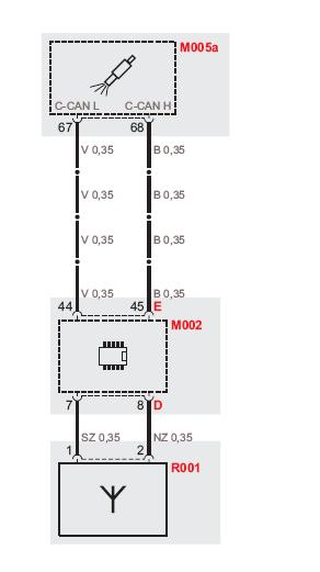
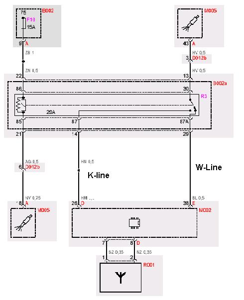
•The above diagram represents the immobilizer system as used on vehicles using the Florence architecture (M139 and M145) and fitted with MotronicME7.1.1 system.
•After reading the key code from the ignition key, the body computer asks confirmation of the key code to the engine control unit over the C-CAN line.
•The W-line (ISO 9141) is used as a back up safety line for the immobilizer system.
•At ignition On, the body computer performs a check of the integrity of the W-line.
•Shortly after, the engine control unit activates the immobilizerrelay to connect to the Kline (ISO 9141), enabling by this way the possibility for diagnostics read out.
On the M138 model, whichhasno C-CAN line, the W-lineisthe main communicationmedium forthe immobilizer function.
On vehiclesusingthe MotronicME9 enginecontrolsystem, the K-line tothe enginecontrolunitand the W-linehavebeendropped. Immobilizer functionisusingC-CAN onlyforcommunicationbetween the body computer and the enginecontrolunit. Consequentlythe immobilizer relayhasbeendroppedalso.
Immobilizer ME9:
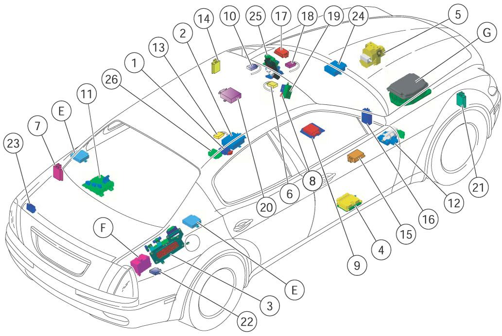
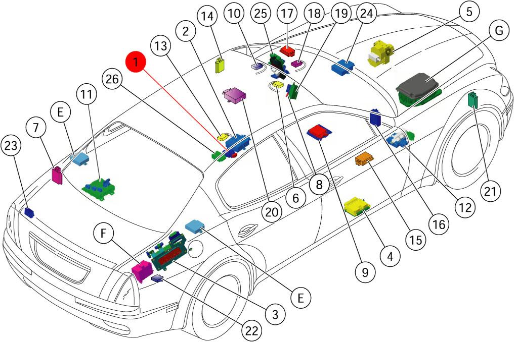
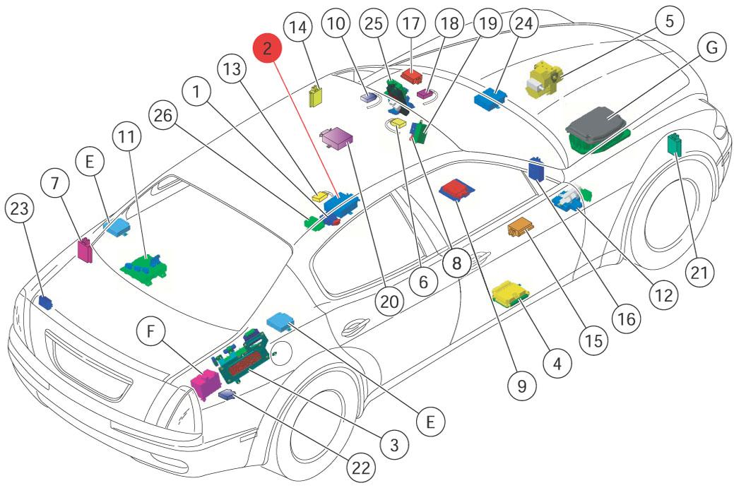
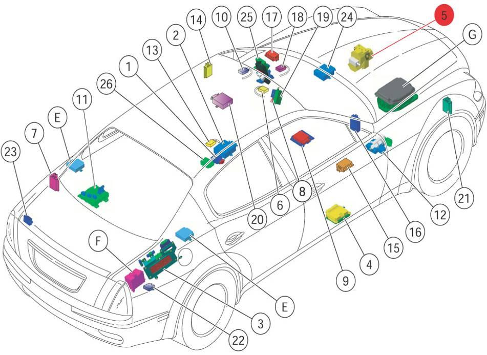
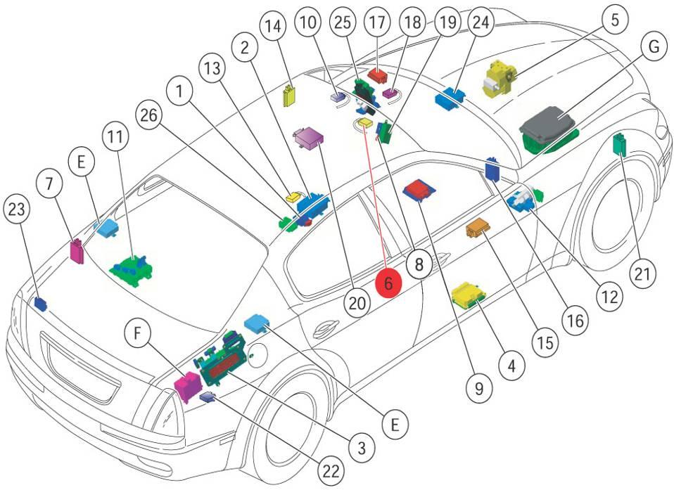
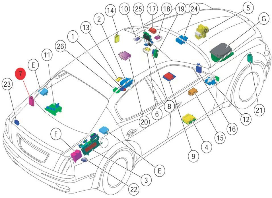
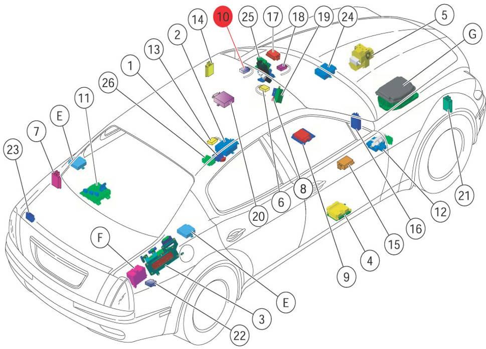
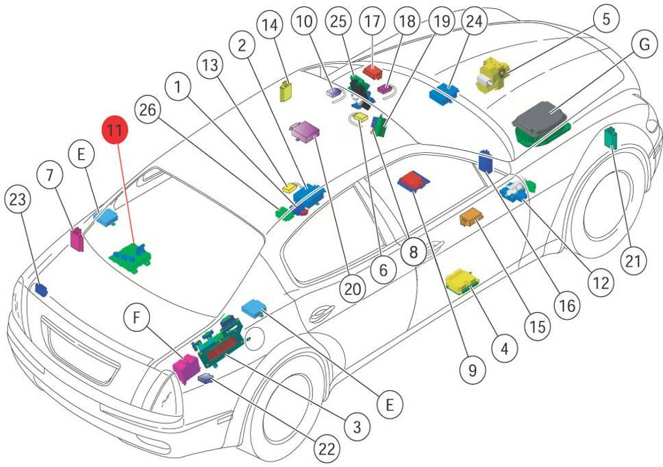
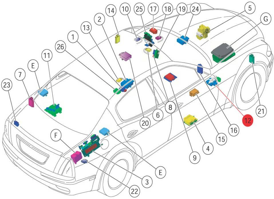
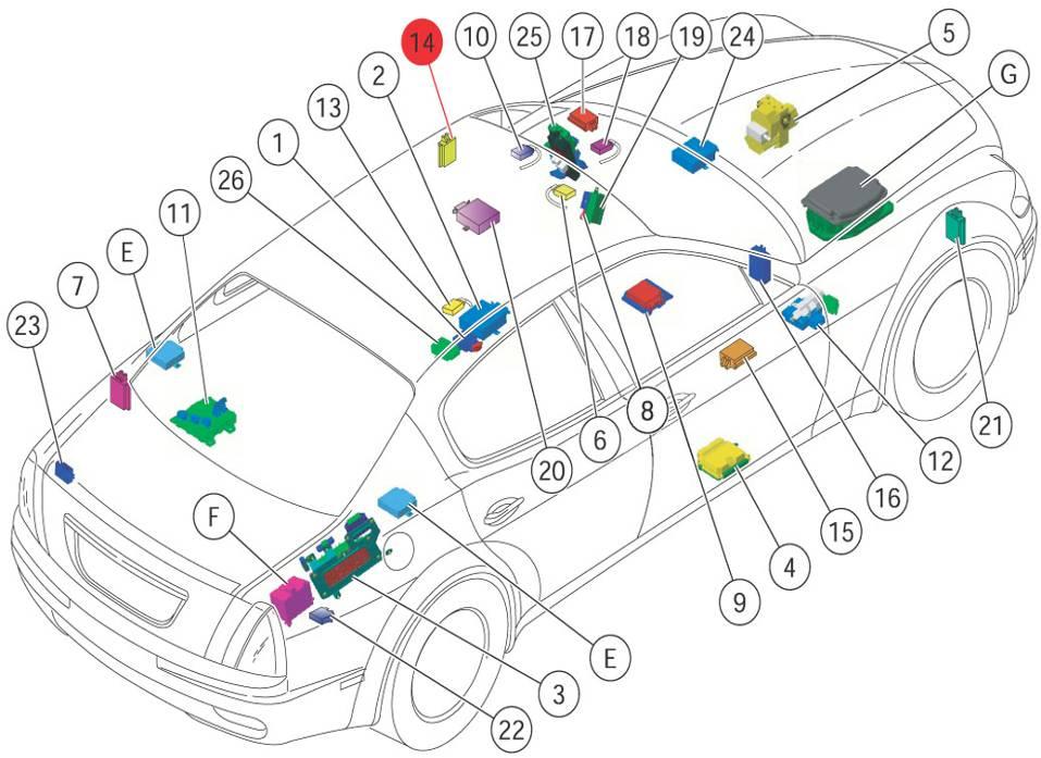
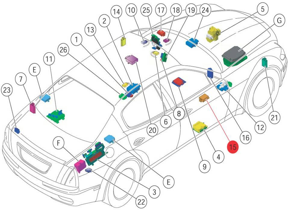
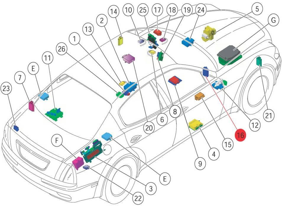
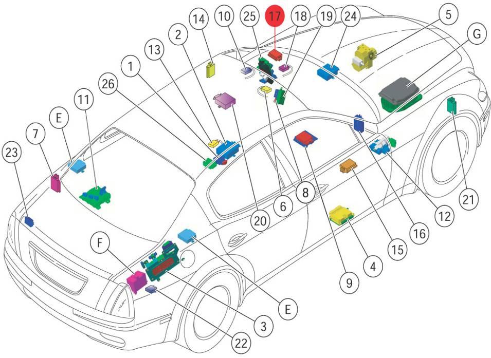
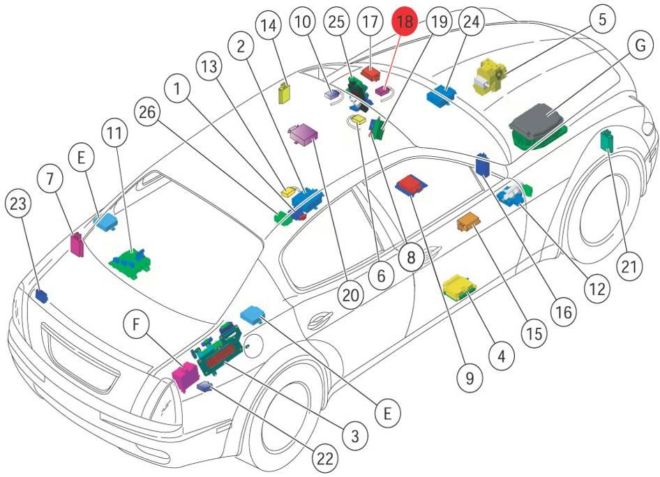
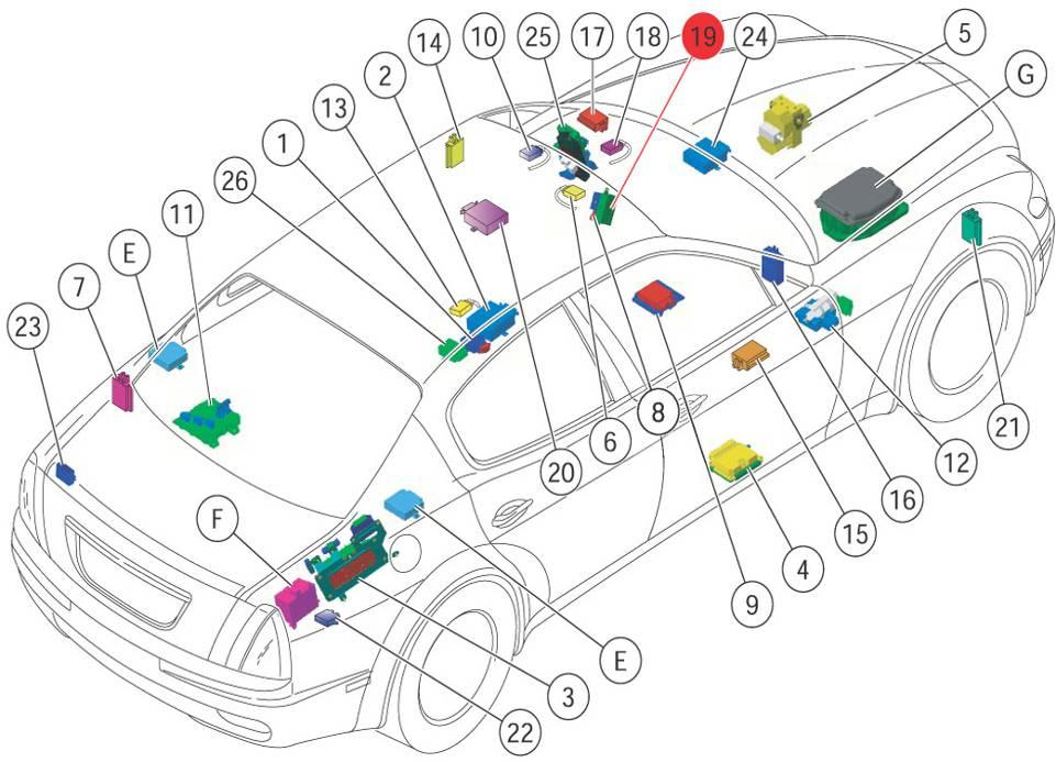
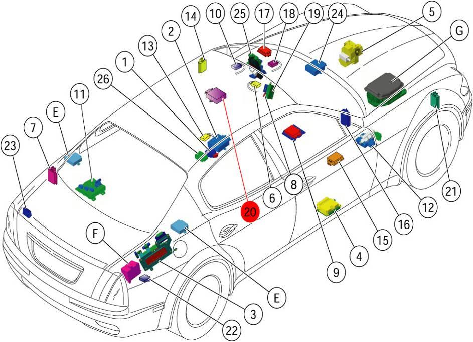
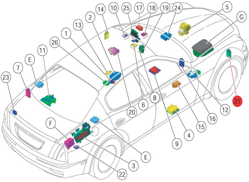
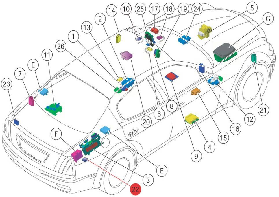
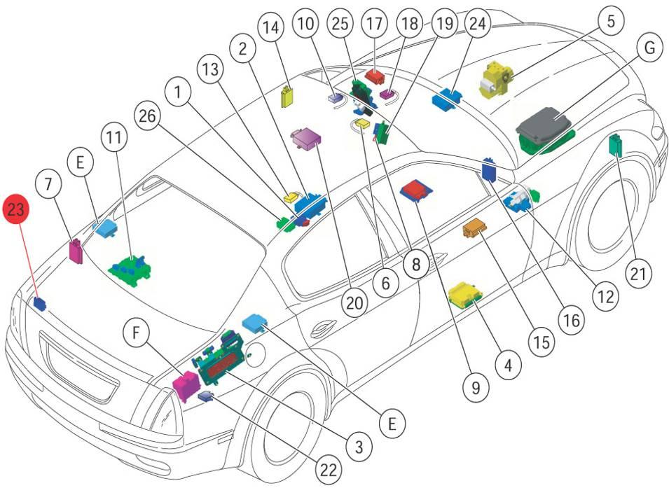
POSITION OF ECUsAND NODES
HEADLIGHT SET-UP ECU (CAF)
The Headlight Set-up ECU (CAF) interconnects with the front wiring.
It manages the following functions:
•CAF failure warning light control (directly to the control panel)
•It receives a signal from the front axle potentiometer, and a signal from the rear axle potentiometer,
•Positive signal for headlights enable from CPL
•It receives a vehicle speed signal from the brake system node (NFR)
•Right and left-hand adjuster actuator (vertically only)
SUSPENSION CONTROL NODE (NCS)
The suspension control node manages information on the followingnetworks:
•C-CAN (information, data),
•K LINE (diagnostics)
It manages the following functions:
•Accelerometer on front RH and LH shock absorber fitting.
•Accelerometer on front RH and LH wheel
•Accelerometer on rear cross member
•Via C-CAN, it reads the vehicle speed, the steering angle and other information
•It manages the shock absorbers’solenoid valves (operated when power supply is connected)
ROBOTIZED GEARBOX NODE (NCR)
The robotized gearbox node manages information on the following networks:

•C-CAN (information, data)
•K LINE (diagnoses)
It manages the following functions:
•Selectionsolenoidvalves
•Engagement solenoidvalves
•Clutchsolenoidvalve
•Relay for pump (new type)
•Clutchposition sensor
•Engagement position sensor
•Selectionposition sensor
•Reverse lightsrelay
•Tachometer input signal from engine control node (NCM)
•It acquires the M/A Shift, Ice (Low grip) commands
ENGINE CONTROL NODE (NCM)
The engine control node (NCM) is connected to the following networks:
•C-CAN for data transfer with other vehicle systems (MotronicME9: also for diagnostics)
•K-line for diagnostics (only for MotronicME7)
It manages the following systems and components:
•Complete engine control system (injection, ignition, throttle, intake timing variation)
•Secondary air system
•Catalytic converter protection strategy
•Cooling fans
•A/C compressor activation
•Immobilizer function
•Engine oil pressure and level warning lights
•MIL activation
•Fuelpump, EVAP system, DMTL system
Note: on vehicles fitted with the MotronicME9 system, the NCM is fitted in a new location in the engine compartment.
BRAKE SYSTEM NODE (NFR)
The interface with the brake system manages information on the following networks.
•C-CAN (information, data)
•K LINE (diagnoses)
The brake system node is connected to the front wiring
It manages the following functions:
•Yawsensor
•Wheel speedsensors
•System pressuresensor
•MSP Off button
•Hardware signal for vehicle speed
•It receives the steering angle signal from the steering angle node (NAS)
STEERING ANGLE SENSOR NODE (NAS)
The Steering Angle Sensor Node performs the following functions:
•It receives and transmits information via C-CAN line
•It interconnects with the front wiring to send information to the brake system node (NFR)
•It sends a signal to the suspension control system:
N.B: in the event of repairs/operations on the steering system, thesensor must be calibrated.
PARKING SENSOR NODE (NSP)
The Parking Sensor Node performs the following functions:
•It receives and transmits information via B-CAN line (e.g.: data, commands) and diagnoses
•It interconnects with the front, rear and rear bumper wiring.
It manages the following functions:
•Front and rear buzzer signal
•Frontsensorsenablebutton
•Trailer attachment set-up
•Warning light on NSP button
•Frontsensors
N.B: The ECU differs depending on whether the vehicle is fitted with front and rear parking sensors or just rear sensors.
The CSG interconnects with the front wiring and manages information via the following network:
•K LINE fordiagnostics
It manages the following functions:
•Negative control signal for failure warning light
•It operates the solenoid valve (when powered)
•It receives a vehicle speed signal from the brake system node (NFR)
AIRBAG NODE (NAB)
The airbag system interface is set up for connection via B-CAN line.
The Airbag Node performs the following functions:
•It receives and transmits information via B-CAN line
•It interconnects with the dashboard wiring (blue connector) and the passenger compartment wiring (brown connector)

It manages the following functions:
•Passenger airbag cut-out (not USA version)
•Frontpassenger's side airbag
•Frontdriver’s side airbag
•Rearand front pretensioners
•Front satellite signal (crash zone sensors)
•Side Bags
•Head Bags
•Signal from seat belts fastened sensor (Buckle switches)
•Side satellite signal
STEERING WHEEL NODE (NVO)
The Steering Wheel Node performs the following functions:
•It receives and transmits information via B-CAN line (e.g.: commands)
•It interconnects with the dashboard wiring by means of the clockspring
•It manages the controls on the steering wheel
•It does not have a diagnosis function
LUGGAGE COMPARTMENT NODE (NVB)
The Luggage Compartment Node performs the following functions:
•It receives and transmits information via B-CAN line (e.g.: diagnosis, warning lights, commands, data)
•It interconnects with the rear wiring
It manages the following functions:
•All the rear door devices
•Positive control signal for rear headrest lowering electromagnets.
•Luggagecompartmentopening/closing
•Luggagecompartmentlighting
•Rear windows sunshade lowering control
•It receives the signal from the inertia switch
HEATING, VENTILATION AND AIR CONDITIONING NODE (NCL)
The air conditioning and heating system interfaces with the rest of the vehicle by means of specific sectioning.
It has pre-assembled wiring (specific serial line for actuator management)
It is connected to the B-CAN line
It monitors and manages the air conditioning and heating system and the passenger compartment ventilation system.
It manages the following functions:
•Anti-pollutionsensor
•Demistingsensor
•Sunlightsensor
•Actuators
•Ventilation
This node is located underneath the driver’s seat. It receives and transmits information via B-CAN line (e.g.: diagnoses/commands)
It manages the following functions:
•Seat and steering column movement
•Memorisationof the seat / steering column / external rear view mirror positions
•Memorisationof the external rear view mirror positions on the passenger’s side in reverse gear
•Easy entry / exit function (enabled / disabled with the NIT)
•Seat heating(opt.)
DRIVER'S DOOR NODE (NPG)
The Driver's Door Node is an ECU incorporated into the controls.
The Driver's Door Node performs the following functions:
•It receives and transmits information via B-CAN line (e.g.: diagnoses, warning lights, commands, data)
•It integrates the four doors’power window controls and the rear windows’inhibit control
•It interconnects with the wiring on the front door on the driver’s side
•It acquires the outside temperature signal
•It acquires the door lock control signal on the dashboard
•It acquires the mirror control signals
•It manages the power window and the anti-trapping mechanism on the driver’s side
•External rear view mirror movement on driver’s side
•Lock / unlock driver’s side door
•It manages the step lights under the door and the mirrors and the courtesy lights at the driver’s feet
PASSENGER’S DOOR NODE (NPP)
The Passenger's Door Node is an ECU integrated with the power window control.
The Passenger's Door Node performs the following functions:
•It receives and transmits information via B-CAN line (e.g.: diagnoses, warning lights, commands, data)
•It incorporates the front power window control on the passenger’s side
•It interconnects with the wiring on the front door on the passenger’s side
•It acquires the door unlock control signal on the dashboard
•It manages the power window and finger-trap prevention device on the passenger side
•External rear view mirror movement on passenger’s side
•Lock / unlock passenger’s side door
•It manages the step lights under the door and the mirrors and the courtesy lights at the passenger’s feet
IMPERIAL NODE (NIM)
The Imperial Node performs the following functions:
•It receives and transmits information via B-CAN line (e.g.: diagnoses, warning lights, commands, data)
It manages the following functions:
•Gearboxfluidlevelinput
•Frontceilinglight
•TyrePressureCalibration(opt.)
•Glovecompartmentopening
•It manages the repetition of the ‘passenger airbag Off’warning light located on the ceiling light
•Serial line to analogue clock.
INSTRUMENT PANEL NODE (NQS)
The Instrument Panel Node is an electronic microprocessor which performs the following functions:
•It receives and transmits information via B-CAN line (e.g.: diagnoses, warning lights, commands, data)
•It interconnects with the dashboard wiring
•It manages all the information displayed on the control panel.
RAIN/TWILIGHT SENSOR ECU (CSP)
The rain and twilight sensor ECU interfaces with the CAN line, with the windscreen wiper ECU (CTC) and with the body computer node (NBC) (for the twilight sensor)
It manages the following functions:
•Serial A-BUS line to rain/twilight sensor
•+15 for twilight/rain sensor ECU
WINDSCREEN WIPER ECU (CTC)
The Windscreen wiper ECU is an electronic and electromechanicalcontrol unit which operates the windscreen wiper motor according to the informationreceived via the A-Bus from the rain sensor and the steering column stalk commands (wired directly)
The CTC interface performs the following functions:
•It receives and transmits information via serial line (rain sensor signal, windscreen wipers activated)
•It interconnects with the front wiring
•1st and 2ndspeed control signal from steering column stalk
•Rain sensor sensing range controlled from steering column stalk
•Windscreen washer pump control signal from steering column stalk
•Power supply for windscreen wipers ECU
•Power supply for windscreen wipers
MOTION-SENSING ALARM ECU (CAV)
The CAV is an electronic component supplied with the front ceiling light which is connected to the serial A-bus line by means of the inside roof panel wiring.
It incorporates the motion-sensing anti-inclination sensors and it manages the motionsensors' deactivation buttons
ALARM SYSTEM SIREN ECU (CSA)
The Alarm System Siren ECU performs the following functions:
•It receives/ transmits information regarding diagnosis and attempt theft to the body computer node (NBC) via serial A-BUS line.
•It interconnects with the front wiring
TV NODE (NTV)
The module consist of a Diversity Television receiver with aerials incorporated into the rear window
It interfaces with the user by means of the NIT via I-CAN
It interfaces with the television wiring harnass.
HI-FI AMPLIFIER SYSTEM (DSP)
The hi-fi system amplifier interconnects with the rear wiring.
It manages the following functions:
•Signal for front and rear woofer.
•Rear LH and RH speaker
•Centralspeaker
•Secondaryamplifiersactivation.