30 minute read
RobotizedGearbox


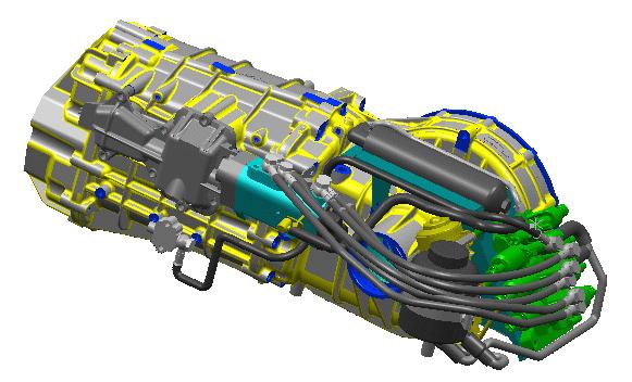
The robotized gearbox control system is composed of an electro-hydraulic servo system which manages the gearchangeand clutch operation. A specific ECU (NCR) controls the complete system by using a strategy which is based on driver inputs and various vehicle parameters. Therefore the NCR interacts with other vehicle systems (NCM, NFR,…) and uses a driver interface (gearshift paddles and control buttons). A specific characteristic of the system is that it canbe integrated on a mechanical transmission without requiring any specific modifications.
Driver controls:
•Display
•Steeringwheelgearshiftpaddles
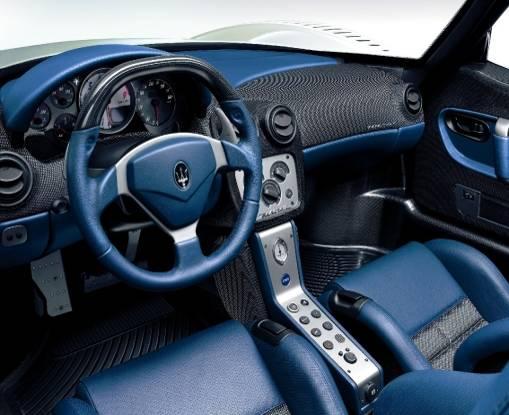
•Reverse
•Auto/manualmode selection
Evolution Of Transmission Control Systems
The robotizedgearboxcontrolsystem wentthrougha numberofsignificantmodifications thathavealsoinvolvedthe introductionand modificationofspecificcomponents. Various software and hardware evolutionshavebeen appliedduringthe yearswiththe aimto improvedrivingcomfort, reduce gearshifttimes, reduce clutchwear and simplifyservice operations.
• PRE-SOFAST and SOFAST transmissioncontrol system (CFC201): thisisthe first generation oftransmissioncontrolsystem asintroducedin 2001 on the M138 model. The nameSOFAST (soft + fast) wasintroducedlittlelaterwhena newcontrolsoftware wasappliedwiththe aimtoimproveoperatingcomfort. Management of gearchangesis notinfluencedbyinformation concerningvehicledynamics.
• SOFAST II transmissioncontrol system (CFC231): a newcontrolunitwithnew software wasintroducedtooptimisegearchange comfort and reduce noiselevels. An improvedoperatingmanagement ofthe clutchwasobtainedbythe introductionofthe Kisspointself-learningprocedure. Management of gearchangesisnotinfluencedby information concerningvehicledynamics.
• SOFAST III transmissioncontrol system (CFC301): the introductionofSofastIII involvesa newcontrolunitand the introductionofa longitudinalaccelerationsensor and a clutchpressuresensor. The longitudinalaccelerationinformation allowsa gearchangeand clutchmanagement influencedbythe vehicledynamics. The clutch pressureinformation allowsthe ECU to calibrate the clutchdiaphragmspring characteristic. Thesemodificationsresultedin a muchimprovedcluchmanagement.
• SOFAST III+ transmissioncontrol system (CFC301): identicaltoSOFAST III butwith modifiedclutchand newoperatingsoftware forfurtherimprovedcluchmanagement.
• SOFAST IV transmissioncontrolsystem (CFC301): newoperatingsoftware and varioushardware modificationsare applied. The introductionofthe Superfast gearshift operatingstrategyreducesgearshifttimesto100 ms.
MASERATI M138 Cambiocorsa
HW CFC 201 (SOFAST) up toassembly12203
HW CFC 231 (SOFAST II) fromassembly12204
MASERATI M139 Duoselect, EUROPE version

HW CFC 231 (SOFAST II) up toassembly18821
HW CFC 301 (SOFAST III) fromassembly18822
HW CFC 301 (SOFAST III+) fromassembly21925
MASERATI M139 Duoselect, US version
HW CFC 301 (SOFAST III) up toassembly21925
HW CFC 301 (SOFAST III+) fromassembly21926
MASERATI M145 MC-Shift
HW CFC 301 (SOFAST IV)
MASERATI M144
HW CFC 201 (SOFAST)
ALFA ROMEO 8C Competizione & 8C Spider
HW CFC 301 (SOFAST III+)

Component Description
Hydraulicactuator
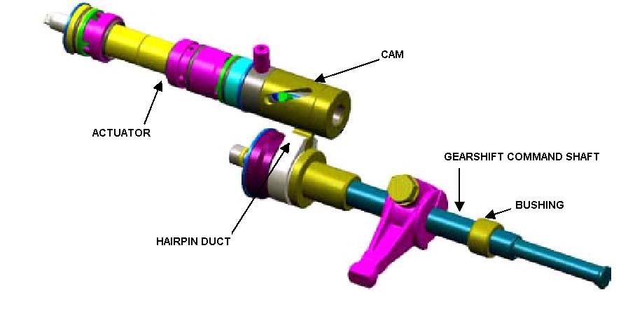
The functionofthissubsystemisthatofdirectlyactivatingthe gearshiftforksin orderto drive the gearengagement and selectionmovements.
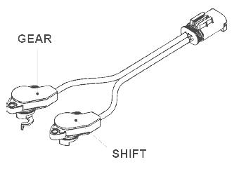
The hydraulicactuatorisequippedwithtwo sensorsdesignedtomonitor the actual position ofthe gearengagement finger. Onesensormonitorsthe selectionstrokewhilethe otherchecksthe gearengagement stroke. Bothsensorsare ofthe contactlesstype(Hall effect). The integratedelectronic circuitin the sensorconvertsthe output signalofthe Hall ceramicelementintoan0-5V DC signal. A failureofthe sensorswillenablea safety strategythatpreventsenginestarting.
Selection
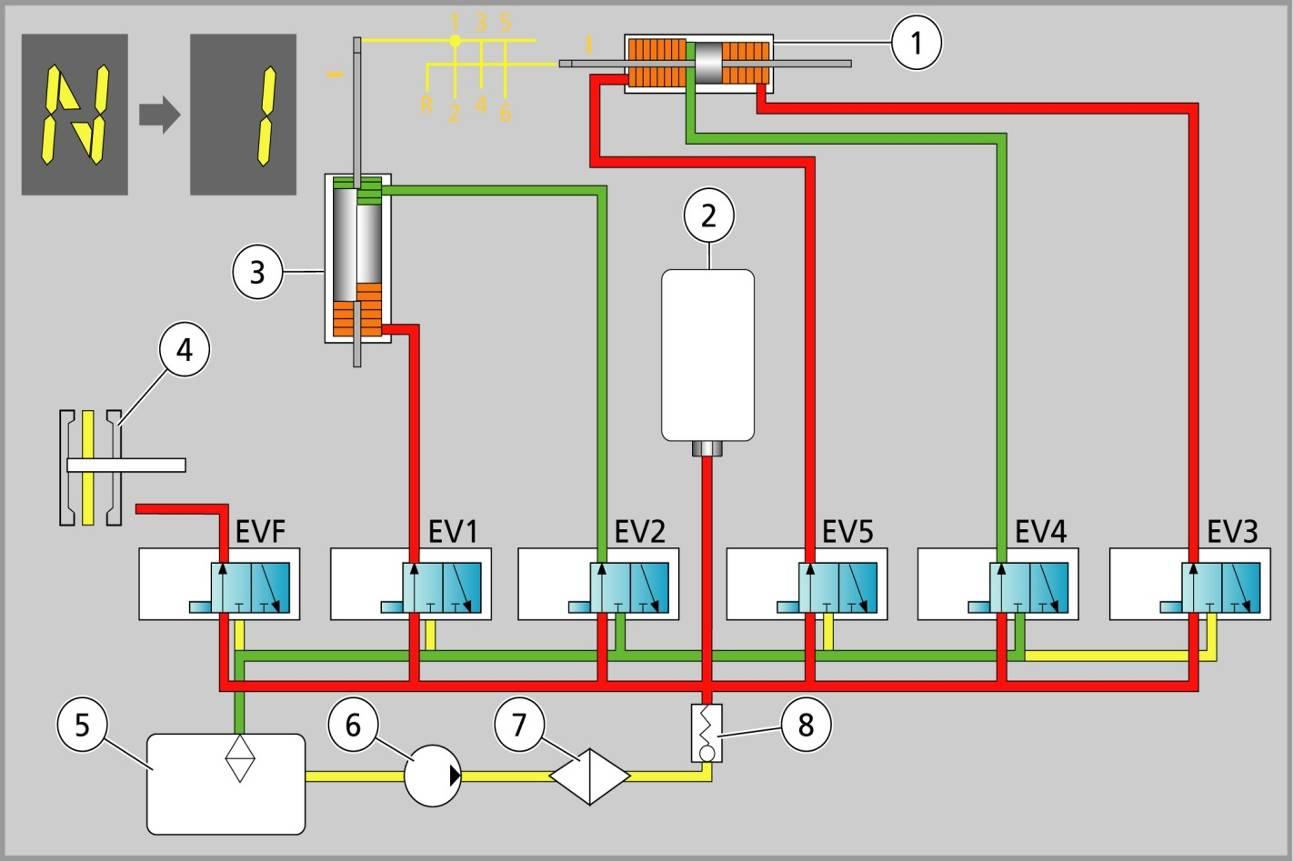
The hydraulicactuatorconvertsthe hydraulicpressuresuppliedbythe gearselection solenoidvalves(EV3, EV4, EV5) intoa rotarymovementofthe gearshiftcommandshaft. The gearshiftcommandshafthas4 possiblepositionsseparatedby15°angles.
Gear EV3 EV4 EV5
1 -2 ON OFF ON
3 -4 ON ON ON
5 -6 OFF ON ON REV ON OFF OFF
Engagement
The hydraulicactuatorconvertsthe hydraulicpressurederivingfromboththe gear engagement solenoidvalves(EV1 foroddnumbergearsand EV2 forevennumbergears) intotravelofthe gearhiftfinger tothree possiblepositions: Evennumbergearsand reverse gear/ Neutral/ Oddnumbergears.
Gear EV1 EV2
2-4-6-R OFF ON Neutral ON ON 1-3-5 ON OFF
PowerUnit
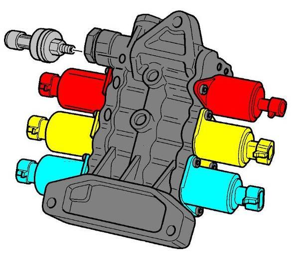
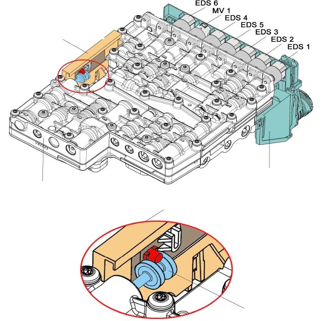
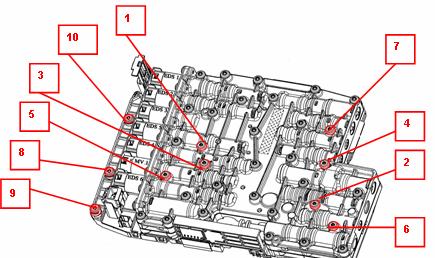
The PowerUnitisheartofthe system. The functionofthissubsystemisthatofmanaging the actuationofthe hydraulicactuatorand the clutchreleasebearing. Thereforeit provideshydraulicenergybyusingvarioussolenoidvalves. The powerunitcontainsthe followingcomponents:
•6 solenoidvalves
•Pressuresensor
•Checkvalve
•Pressurereliefvalve
•Bypass
Pressuresensor:
Workingrange: 0 -80 bar
Powersupply: 5V DC.
Output signal: 0.5 -4.5 VDC.
Solenoidvalves:
EV: Clutchsolenoidvalve (PFV)
EV 1-2: Gearengagement solenoidvalves(PPV)
EV 3-4-5: Gearselectionsolenoidvalves(PFV)
Checkvalve
The checkvalve islocateddownstream from the electricpumpinside the PowerUnitand servestopreventthe oil fromflowingbackwards. The presenceofthe checkvalve makes itpossibletomaintainhydraulicpressurein the PowerUnitwhenthe electricpumpisnot runningso thatoperatingpressureisimmediatelyavailablewhenthe ignitionswitchedto ON.
Pressurereliefvalve
The pressurereliefvalve preventsdamagetoF1 system componentspotentiallyresultingfrom excessoil pressurein the eventofanomalous operationofthe oil pump. The pressurereliefvalve opensat approximately90 bar and dumpsthe oil to the low pressureside ofthe circuit.
The bypass screwmakesitpossibletoconnectthe high pressurecircuittothe low pressurecircuitto relievesystem hydraulicpressure. Thisoperationis required, forexample, whenrenewinghydraulic system components.
ProportionalPressureValve (PPV):
The twogearengagement solenoidvalves (EV1, EV2) responsibleformeshingand disengagingthe gears, are of the proportionalpressuretype(PPV). The solenoidvalves are controlledbya PWM signaland theymodulate hydraulicpressurein accordancewith the input current
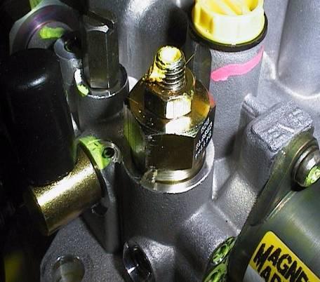
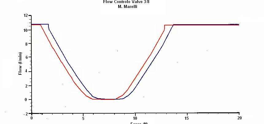
ProportionalFlow Valve (PFV):
The 3 gearselectionsolenoidvalves(EV3, EV4, EV5) and the clutchsolenoidvalve (EV) are ofthe proportionalflow type(PFV). The clutchsolenoidvalve iscontrolledbya PWM signaland modulateshydraulicpressurein accordancewiththe input current. The three selectionsolenoidvalvesare usedasOn/Off typevalves.
Clutchsolenoidvalve flow curve
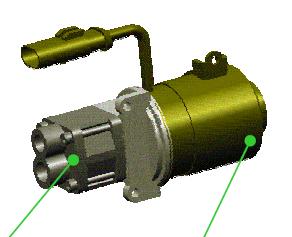
Electricpump
The electricpumpbringsthe oil fromthe hydraulicreservoirtothe operationalpressurefor the powerunit.
The pumpisdrivenbyanelectricDC motor and ismanagedbyanON/OFF control strategy(the pumpdoesnotruncontinuously). The pumpisactivatedwhenhydraulic pressuredropsbelow40 bar and isswitchedoff whenthe pressurereaches50 bar. Whenthe driver's side doorisopenedand the ignitionkey isnotinserted, the transmission controlmodule(NCR) runsthe pumpbrieflytobuildup hydraulicpressurebeforestarting the engine.
In case of replacement of the electric pump, the pump must be replaced together with its activation relay!
Pump Electricmotor
Sofast4:
For the Sofast4 system (GranTurismoS) with Superfast shift strategy, a higher operating pressure is obtained when the superfast shift mode is active (range 50 -70 bar). Therefore, a new, more powerful electric pump is used. Further, an air conveyor is installed to provide fresh air to the pump for heat removal. The temperature of the electric pump motor is monitored by the NCR by means of a mathematical model. In base of certain temperature thresholds, specific recovery strategies can be activated to prevent overheating of the pump.
Pressureaccumulator
The system isequippedwitha pistontypepressure accumulatorlocatedon top ofthe gearbox. The functionofthisdeviceistoaccumulate hydraulic pressureduringthe electricpumprunningtimeand deliverhigh pressureoil tothe powerunitwhenthe pumpisstopped.
Solenoidvalvesinternalleakage
Leakagepastthe spoolofthe controlvalve, whichisestimatedby the NCR and can be readout bythe diagnosticsystem, constitutesa valuablediagnosticaidin the eventofan electrohydraulicsystem fault. The valueshownisperiodicallyacquiredbythe NCR in a self-learningprocedure.
Solenoidvalve internalleakagein excessof30 cc/min, combinedwithproblemsof engagement and/or selection, offersanexcellentpointofreferencetounderstandthe nature ofthe problem. In thiscase the solenoidvalve mustberenewed. In the case ofhydraulicproblemsusethe followingprocedure in ordertoisolate the offendingcomponent:
Key ON, EngineOff: the intervaltimebetweentwopumpactivationsmustbeno less than2 minutes. Thismakesitpossibletocheckthe solenoidvalves-accumulatorelectricpumpassy.
Key On, Enginerunning: the intervaltimebetweentwopumpactivationsmustbeno lessthan60 seconds. Thismakesitpossibletocheckthe clutchsolenoidvalve and, by acquiringthe pumprestarttimes, the conditionofthe accumulator.
The conditionsofthe electricpumpcan beassessedbyacquisitionofitsactivationtime: anactivationrampwithanincreasinglygradualslopeand activationtimein excessof5 secondsare clearsymptomsofdeteriorationofthe pump.
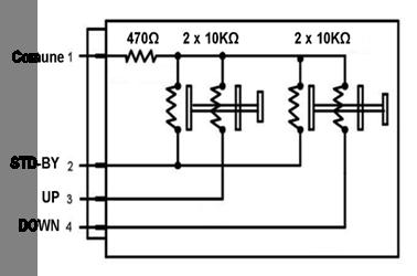
Up / down paddles
Selectionofgearengagement bymeansofsteeringwheelpaddles
The NCR checksthe activationstatus ofthe paddlesbymeansofvoltagevalues generatedbyactivationofthe gearshiftpaddles.
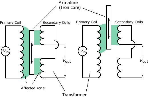
Clutchposition sensor
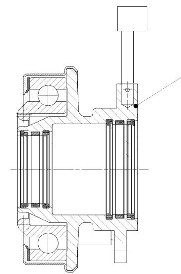
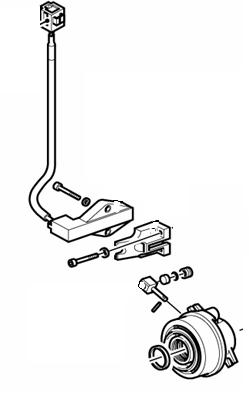
A contactlesstypesensorisusedtomeasurein realtimethe position ofthe clutchrelease bearing. ThissensorusesLVDT (Linear VariableDifferentialTransformer) technology. The movementofa magnet, fittedon the releasebearing, willaffectthe voltageinducedin the coilsintegratedin the sensorelement.
Note: failureofthe clutchposition sensor mayleadnon-startingofthe engine.
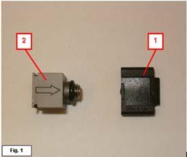
ClutchActuator
The clutchactuatorisresponsibleforactivatingthe clutchthrustbearing; the actuatoris composedofa hydraulicallyoperatedcircularring. Attentionmustbepayedtothe correct direction ofinstallationofthe position sensormagnetwithreferencetothe clutchthrust bearingposition.
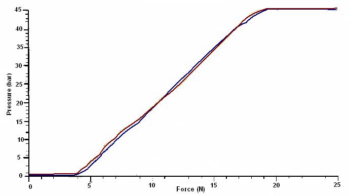
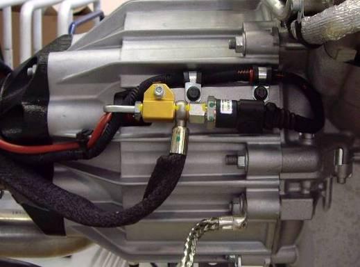
Hydraulicpressuresensoron clutchhousing(SofastIII onward)
An analoguepressuresensormeasuresthe hydraulicpressurein the clutchactuator, whichisin directrelation tothe applicationforceofthe diaphragmspring. Bythisway the exactclutchcharacteristiccan beidentified. Thiscomponentisinstalledstartingfrom sofastIII.
Measuringrange: 0 -80 bar
Responsevoltage: 0.5 -4.5V
Longitudinalaccelerationsensor(SofastIII)
A longitudinalaccelerationsensorwas introducedon the SofastIII system toallowto calculatethe road gradient(flatsurface, uphill, downhill). Thisinformation isusedbythe NCR toadaptthe clutchactivationduringdrivingaway and the gearshiftstrategyin automaticdriving mode in base ofthe road gradient.
Startingfromassembly 24275, the sensorhas beendroppedand longitudinalacceleration ionformationisreceivedfromthe ABS / ESP system (NFR) overthe C-CAN line.
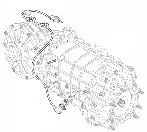
The rotation speedofthe gearboxprimaryshaft ismonitoredbya magneticinductiontypespeed sensorlocatedon the right-handside ofthe gearbox.
Sofast4:
For the GranTurismoS model (Sofast4), the following hardware modifications have been made:
•Reinforced gearbox housing (new differential lid)
•Reinforced, three-pad gearshift forks made of a new material
•New clutch “Ribbed finger”(PIS value still 4,2mm –327 bit)
•New clutch housing with double support bearing
•New electric pump with increased capacity and air conveyor
•Clutch position sensor with improved thermal isolation for wiring
•New hydraulic circuit oil: Shell DonaxTX (0,5L)
•High pressure leads without restrictors: on previous generations, restrictors were fitted in the high pressure leads to reduce operating noise. For Sofast4 they have been removed to allow the increase of gearshift times.
•Direct connection between NCR (pin 80 CFC301) and NCM (pin 81 MotronicME7.1.1) for engine cut-off in Superfast shift mode: When Superfast shift mode is active, the fuel cut-off command during gearshift to the engine control system is notgiven over the CCAN line but by a direct connection by an “active low”signal. This allows a faster command and improved synchronisation between gearbox control andengine control during gearshift phase.
• Note: in case of failure of the line (interruption, short circuit) a specific error code will be stored (DTC P1761) and the Superfast shift mode will be disabled.
•Activation of reverse lights via CAN: pin 41 of the CFC301 unit is no longer used to operate the reverse lights relay. Instead, it operates the LED behind the Reverse button on the control panel located on the central console.
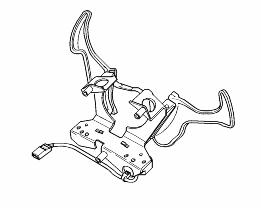
•Improved driver interface with longer gearshift paddles at the steering wheel and a new control panel to select the driving direction (1st gear or Reverse).
The various modifications result in a modified pin-out for the CFC301 ECU with respect to SofastIII and SofastIII+
Operating Principle Chart
PilotPilot
Up/Down levers
Sport -Icebuttons
BrakePedalSwitch
MotronicMotronic
Engine Speed(rpm) -CAN
Requiredtorque-CAN
Speed(km/h) -CAN
Single wheelspeed-CAN
TCU
Selectionposition sensor
Engagement position sensor
Clutchposition sensor
GearboxprimaryRPM sensor
Doorand Hood Switch
PressureSensor
GearShifting
ClutchPosition Control
SensorsSensors
Input signals
Fault Warning
Light
GearIndication
Dashboard ActuatorsActuators
Dashboard
The transmissioncontrolmodule(NCR) usesthe followinginput signalsforoperationof the gearboxand clutch:
Analogueinput signals:
•Shiftup selector
•Shiftdown selector
•Vehiclespeedsignal
•"Ice" switchsignal (low grip)
•"Auto" switchsignal
•"Reverse" switchsignal
•Brakepedalswitch
•Driver's doorswitch
•"KEY ON" signal
Input signalsfromdifferentsensors:
•Shiftactuatorposition sensor
•Selectionactuatorposition sensor
•Clutchactuatorposition sensor
•Clutchpressuresensor(SofastIII onward)
•Primaryshaftspeedsensor
•Oil pressuresensorpowerunit
CAN input signals:
•Engine speedsignal
•Engine torquesignal
•"Sport" activationsignal(fromNFR)
•Hood switchsignal
•Brakepedalswitchsignal
Clutch Operation Management
Clutchoperationmanagement, and allstrategiesrelatedthereto, isbasedon controlof the clutchposition calculatedin realtime. The clutchcontrolstrategiesare basedon absolutereferences:
•clutchposition
•transmissibletorque
Calculationand controlofthe torquetransmissibilitycurve dependson two positions:
1.KISS POINT (PIS position)
2.CLOSED CLUTCH POSITION
The kisspoint–alsoreferredtoasthe PIS (Punto Incipiente Slittamento or slip beginning point) –isa parameterthatdefinesthe nominalvalueofthe clutchengagement pointin the gearboxcontrolmodule(NCR). The kisspointisthe actual thrustbearingposition at the moment ofclutchengaging, expressedin millimetresand in relation tothe closed clutchposition. The kisspointdependson variousfactorssuchasthe clutchdisc surface conditionand clutchtemperature. Itdoesnotdependon clutchwear
The kisspointisreachedat between1020 -1040 RPM. The clutch“closes”and therefore full torquetransmissionisattainedat 1800 RPM. Whendrivingat below1800 RPM and especiallywhentravellinguphill, the temperature ofthe clutchdisc tendstorise due tothe clutchnotbeingfullyclosedcausingclutchslip. Thisresultsin disc wear and drastically reducesthe lifespanofthe clutch.
The kisspointcan beset intothe NCR modulebymeansofa calibrationprocedure with the SD3 diagnostictester. Thisprocedure shouldbecarriedout afterreplacementofthe clutchor the transmissioncontrolmodule. Sincethe temperature isanimportantfactorfor the determinationofthe kisspoint, the calibrationprocedure shouldonlybecarriedout at the correctclutchoperatingtemperature. Correctcalibrationofthe actualkisspointis crucialforcorrectclutchperformance.
The closedclutchposition: thisisa valuein mm whichdefinesthe thrustbearing position whenthe clutchisfullyclosed. Thisvaluedependson the clutchwear and isautocalibratedaftereachgearshift.
Closedclutch position
PIS value = CC position –PIS position
Calculation of wear:
Autocalibratedclosed clutch value –NEW closed clutch value
Clutch thickness (5.6 mm)
T = New clutch disc thickness t = Worn clutch disc thickness
Δx= offset = T -t
START OF TORQUE TRANSMISSION
X 100 = % Wear on clutch
The kisspointdoesnotdependon clutchwear offset = T -t = 21.6 -16.6 = 5 mm
Clutch Position Control
Real-time clutchopen/closecontrolbymeans ofthe position sensor, iscalculatedusing the PIS valueand the closedclutchposition. Duringgearshifts, the NCR transmission controlmodulebecomesMASTER, whilethe NCM becomesSLAVE and setsa target torquevalue. Once the target torquevalueisreached, the NCM modulerevertstothe MASTER condition.
The threegearengagement phases
a = TorqueReduction
The target torqueis decidedbythe TCU (master)
b = RPM Control
The target torqueis managedbythe TCU (master) (120 ms)
c = TorqueTransmission
The TCU isnowslave and MOTRONIC decides on the target torque value
Flow controlbymeansof I0 CURRENT management. Phase b controlinvolves management ofthe EVF thatcontrolsthe hydraulicflow, in function of in the controlling current. AllMaserati electro-actuatedcontrolsystemsup tosofastII usethistypeof parameter, whichmustbecalibratedin the eventofmalfunctionor maintenanceon the PowerUnit.
Calibrationiscarriedout asfollows:
•Engine runningwiththe gearboxin neutralforapprox. 5 min.
•Engine runningwiththe gearboxin 1st gearand footon the brakeforapprox. 5 min. SOFAST III onwardsystemsexecutethisprocedure usingthe “DEIS”function.
CLUTCH WEAR INDEX (SofastII onward)
The clutchwear index(alsoreferredtoas“clutchwear degree”or “clutchdegradation index”) isa self-learnedparameterwhichisusedbythe NCR toadjustthe clutch management in functionofthe degradationofthe torquetransmissibilitycapacityofthe clutch.
The clutchwear indexcan befoundin the SD3 parametermenu and providesusefull information aboutdegradationofthe transmissibilityofthe clutch. The wear indexisselflearntbythe NCR eachtimethe clutchisin the closingphase.
4000 010000 Clutchbiting brusquely Clutchtendingtoslip
The clutchwear indexisa valuebetween0 (100% torquetransfer) and 10000 (no torque transfer, constantslippingofthe clutch). The default valueis4000. A clutchthatis operatingcorrectlywillhavea wear indexof around3000/4000. Ifthe clutchhasnotbeen replacedand the wear index ishigh, afterperformingthe resettingand subsequentKiss pointprocedures, the valueofthe parametershouldfall. 10
Transmitted torque
P.I.S. Closedclutch position
On SofastII and SofastIII systems, the clutch wear index is used by the NCR to “move up”the torque transmissibility curve which is used as a reference for clutch control. A clutch wear index of higher than 4000, will move the curve to the right, a lower to the left.
For SofastIII+, the calculation of the clutch wear index has been refined. The clutch wear index is no longer one single value, but 5 different points which together will define a new torque transmissibility curve.
Note: the clutch wear index must be reset (= bring back to the default value of 4000) after replacement of the clutch and before performing the Kisspointprocedure.
Note (2): from SofastIII+ onward, the clutch wear index is no longer present in the parameter environment of the SD3 tester unit. The reset command (in the Active diagnoses menu) is still present and will reset all 5 values.
Gear Engagement Strategy
The gearengagement and selectionvaluesare self-learntand storedin the NCR by meansoftwoposition sensorswhichmustbewithinstrictlydefinedranges. Bymeansof thisprocedure, the NCR buildsa gridand checks2 engagement and 2 selection thresholds(MIN and MAX). The calculationgridspreadsheet can beusedtocheckthe correctcentringand movementofthe actuator. Itisadvisabletoexecutea calculationgrid whenthe vehicleisnewand aftereachmaintenanceoperationon the gearbox, and to keepdocumentationarchivedforfuture reference.
Service Operations On The Robotized Gearbox System
Dependingon the typeofoperationperformedon robotizedgearboxsystem components managedbythe NCR module, itisnecessaryto performthe followingoperations, which are dividedintothe relative areasofintervention.
SELF CALIBRATION OF DEIS PARAMETERS (SofastIII onward):
The DEIS parametercalibrationfunctionis a self-learningfunctionwhichrelatestoa numberofclutchoperationfunctions, e.g. self-learningofthe clutchsolenoidvalve and clutchdiaphragmspring.
Bymeansofthe DEIS self-learningprocedure, the transmissioncontrolmodule(NCR) usesa specificalgorithmtocalculatethe springcharacteristicofthe clutchdiaphragm. Thisfunctioncan beactivatedbythe SD3 diagnostictester and shouldbecarriedout after replacementofclutch-relatedcomponentsor the transmissioncontrolmodule(NCR). Toactivatethe function, connectthe SD3 tester and selectthe single ECU menu toenter the transmissioncontrolmodule(NCR). Thenselectthe activediagnosticsmenu where the DEIS self-learningfunctioncan befound.
The procedure hasa durationofbetween3 minutes30 secondsand 9 minutes. In case the procedure hasnotbeencompletedentirely, itisbeenconsideredasfailedand hasto berepeated.
Afterthe procedure hasbeenconcludedpositively, turn off the ignitionkey and waitfor25 seconds. Thistimeisneededforthe moduletomemorizethe differentparameters. Ifthe procedure hasa negative result, trytofindthe cause bycheckingthe correct operatingofthe clutch.
Alsocheckifthe hydrauliccircuithasbeencorrectlybled. Repeatthe procedure.
The aimofthe DEIS procedure istoobtaina fine-tunedcontrolof2 parameters:
1.Clutchposition
2.Clutchsolenoidvalve pressure
The procedure comprisesthe followingsteps:
1.autocalibrationofclosedcentrecurrentforthe clutchsolenoidvalve I0
2.autocalibrationofoptimalDithercurrent
3.autocalibarationofthe dead band ofthe clutchsolenoidvalve
4.autocalibrationofthe current/capacity of the clutch valve
5.autocalibrationofthe clutchBellevillespring
(*)DEIS: Dipartimento di Elettronica, Informatica e Sistematica (DepartmentofElectronics, Computer Sciencesand Systems), UniversityofBologna, whichhascollaboratedwithMaserati on the developmentof the procedure carryingitsname.
RESET CLUTCH WEAR INDEX (SofastII onward):
The clutchwear indexprovides information aboutdegradationofthe torquetransmissibility ofthe clutch. The clutchwear indexisa self-learnedparameterwhichwillinfluencethe management ofthe clutchand whichisspecificforeachclutch. Thereforethe clutchwear indexmustbereset afterreplacementofthe clutchand beforecarryingout the KissPoint procedure.
The reset commandforthe clutchwear indexcan befoundin the Activediagnosismenu ofthe SD3 tester.
Note: with recent diagnostic software, the clutch wear index reset is integrated in the Kisspointprocedure.
CLUTCH CONFIGURATION:
The “clutch configuration”, which is a command in the “Active diagnostic”menu of SD3, is used to store the actual “closed clutch position”, as measured by the clutch position sensor in real time, as the “closed clutch position of new clutch”. Therefore, this operation must only be performed after the installing of a new clutch. Theclutch configuration is crucial for the correct calculation of the clutch wear %.
Note: it is advised to perform the clutch configuration after a briefbedding in of the new clutch.
Note (2): with recent diagnostic software, the clutch configuration is integrated in the Kisspointprocedure.
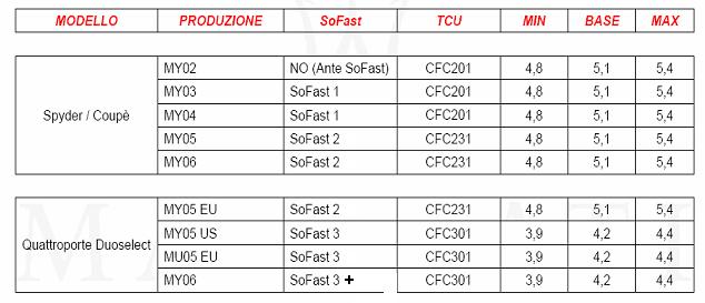
KISS POINT ADJUSTMENT PROCEDURE (Pre-Sofastand Sofast):
ForcarsfittedwithtransmissioncontrolsystemspriortoSofastII (Pre-Sofastand Sofast) the Kisspointvaluemustbeenteredmanualywiththe diagnostictester (SD2). The Kiss pointbase valuedependson the vehicletypeand ModelYear. Afterenteringthe base value, the valuecan beadjustedafteranassessmentofthe clutchin ordertoobtainan optimalclutchbehaviour.
KISS POINT SELF LEARNING PROCEDURE (SofastII onward):
On vehiclesfittedwithSofastII or later, the idealKisspointcan befoundbymeansofa self-learningprocedure whichisactivatedbythe diagnostictester. Beforestartingthe kisspointprocedure, itisfirst necessaryto bedin the clutch:
•Forthe first fewmiles, followthe guidelinesbelowin ordertoallowthe clutchtobed in sufficiently:
•avoidusingsport mode
•changegearat a maximumof4000 rpmand a maximumof50% pedal
•avoidreleasingthe clutchsharply
•avoidprolongeduseofthe clutch(trafficjams, maneuvers)
•makefrequentgearchangeswhiledriving
Keepthe engineidlingfor5 minutestocalibrate the solenoidvalveswhilehot. Withthe vehiclein motion, engage1-2-1 in sequence, and keepthe engineidlingin first and the brakepedalpressedfor1 minute. Repeatthe sequencethreetimestoallowcorrect estimationofclutchsolenoidvalve internalleakage.
•Stop the engine, makecertainthatthe ignitionswitchisin the OFF position
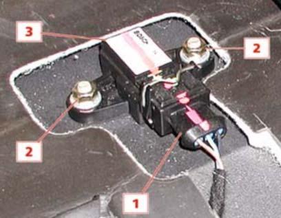
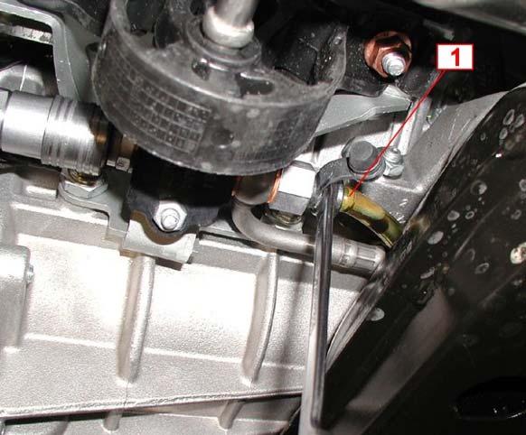
•ConnectSD3 (95970312) tothe EOBD diagnosisconnector (1).
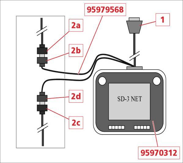
•Connectthe C-Can connector (2a) tothe SD3 cable(95979568)
•Connectthe C-Can connector (2c) withthe SD3 cable(95979568) (2d).
First reset the CLUTCH DEGRADATION INDEX in the NCR activediagnosis environment.
ATTENTION!
Beforeadjustingthe gearengage/selectactuator, makethe followingchecks:
•Ifthe carhasbeenparkedformore than8 hours, drive itfor15 minutesin Free Drive, changinggearrepeatedly.
•Ifthe carhasbeenparkedformore than 30 minutesafterthe bedding-inphase, make10 consecutive breakaways up toanenginespeedof1500 rpm.
•Ifthe carhasbeenparkedforlessthan30 minutesafterthe bedding-inphase, make5 consecutive breakaways up toanenginespeedof1500 rpm.
Switchon the SD3 and selectthe KISS-POINT NCR applicationfromthe listofdiagnosis programs. Selectthe KISS POINT ENVIRONMENT functionfromthe M138 software list. The subsequentphasesare guidedbythe chosendiagnosissystem.
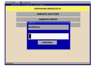
Enterthe serial numberofthe car:
Note: for Sofast4 (GranTurismoS), the Kiss point procedure can be performed by connecting the diagnostic tester to the vehicle EOBD connector (by using the Switch Matrix cable). It is therefore not necessary to use the C-CAN connector cable.
Usethe TAB key toselect"CONTINUOUS", thenpress "ENTER" toconfirm. The system willdisplay a warningmessageforthe operator, remindinghimwhatconditionsthe car mustmeetin orderforthe calibrationprocedure tobeexecutedcorrectly.
Ifthe carmeetsthe necessaryconditionstoproceed, press "ENTER".
Put the gearboxin neutral, turn the ignition switchtothe OFF position, waitforabout15 seconds, thenstart the engineand select"ENTER" on SD3. Select“START PROCEDURE”.
The nextscreentellsthe operatortokeepthe acceleratorpedalpressedforthe full durationofdata acquisition.
The system willautomaticallyrun10 clutchopen/closecycles, withthe gearboxin neutral, duringwhichthe SD3 willacquirethe necessarydata forcalculatingthe kisspoint correctly.
Waitforthe "end ofdata acquisitionprocedure" messagetoappearon the display and for the instrumentpanelnodetogiveanaudiblealertsignal.
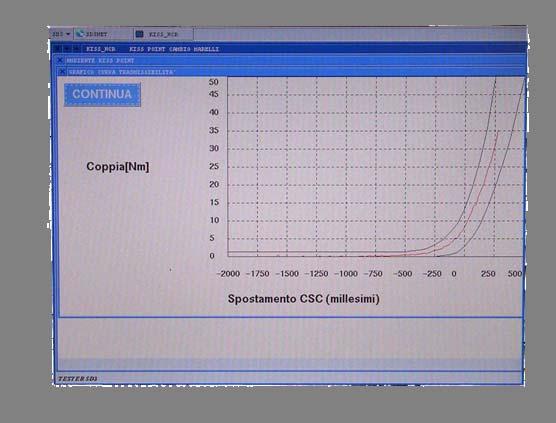
The SD3 display willshow the "TRANSMISSIBILITY" graph, i.e. the torquevalueasa functionofclutchposition (red) and the tworeferencecurves(black), whichindicate the tolerancerangewithinwhichthe torqueransmissibilitycurve mustbepositioned.
The system willautomaticallycheckthatthe torquetransmissibilitycurve fallswithinthe twotolerancecurves.
Dependingon the resultofprocessing, therecan betwodifferentoutcomes:
•The data are correct, and the system willthuscontinue withthe nextphasesofdata acquisition.
•The data are incorrect, the procedure iscanceledand anerrormessageis displayed, showing howtocorrectthe error.
At the end ofeachsequenceofdata acquisitionand processing, the followingparameters willbedisplayed:
•Numberofbreakways
•Kisspointvalue(bit,mm)
•Valueofdispersalofpoints(bit)
Ifcompletedcorrectly, the procedure willberepeatedtwicemore. On completionofthe threephases, the averagekisspointvaluewillbecalculated, and thisvaluewillbesavedbythe gearboxcontrolunit. The SD3 display willshow the message"KISS POINT SAVED CORRECTLY".
SELF LEARNING OF ACCELERATION SENSOR OFFSET (SofastIII onward):
Afterreplacementor disconnection/reconnectionofthe accelerometeror replacementof the transmissioncontrolmodule(NCR), it isnecessarytorunthe accelerometer autocalibrationprocedure.
Thereforethe vehiclemustbepositionnedon a levelsurface, withthe tyresat theircorrect pressureand withcorrectwheelalignment.
The procedure can befoundin the “Activediagnosis”menu ofthe SD3 tester. Thisprocedure shouldtake about30 seconds, witha checkingtimeof40 seconds. Once thistimeisup, ifthe procedure hasnotfinished, ithasfailed.
Ifthe procedure hasbeencompletedsuccessfully, and no furtheradjustmentsare necessary, turn the ignitionkey to“OFF”and waitforat least25 seconds. Minimum time forallowingthe controlunittosavethe parametersread.
Note: forvehicleswithoutdedicatedlongitudinalaccelerationsensor(assembly24275 onward), the longitudinalaccelerationdata isreceivedfromthe ABS/ESP unitbythe CAN line. Alsoin thiscase the sensorself-learningprocedure mustbeperformedin the same way, asthe CAN receiveddata isa rawvalue.
SELF-LEARNING OF THE GEARCHANGE GRID:
The Self-learningofthe gearchangegrid(simplyindicatedby“self learning”) isactivated bymeansofaninstructionfromthe tester withthe carstationaryand the ignitionswitched toOn. Thisoperationteachesthe ECU the areasofengagement and selectionforthe gearboxwithwhichitisassociated. On completionofthe procedure, the system automaticallycheckswhetherlearninghastakenplacecorrectly. Makesurethatthe batteryischarged, the handbrakeisreleased and the carismovingslightly(bypushing) in the eventthatself-learningisblocked due tostickingwhenengaginggears.
Note: In case the self learningdoesnotend successfully, checkifthe hydraulicactuator bleedinghasbeencorrectlyperformed.
Note (2): Selflearningvaluesare storedinside the NCR at the successive “Key Off”.
SELF LEARNING OF THE SUPERFAST SHIFT (Sofast4 onward):
Where the self learning of the gearchangegrid has for purpose to calibrate the travel of the gear selection and gear engagement movement, the Superfast shift self learning has been created to optimize the synchronization of the various gearshift related actions.
MC-SuperFAST
Break in acceleration drops to 100ms t1t2t3
Gear shift time: 40ms
To obtain the shortest possible total gearshift time, it is of upmost importance that the different phases of a complete gearchangeoperation (power cut-off and clutch opening, gear disengagement, gear selection, gear engagement, clutch closing and power restore) are perfectly synchronised. During the Superfast shift self-learning procedure, the NCR will calibrate the duration of the solenoid valve activation andthe actual gearshift for every gear.
This procedure can be activated with the diagnostic tester and needs to follow after completion of the self-learning of the gearchangegrid.
Note: in case the Superfast shiftself learningprocedure hasnot beenperformed, a specificDTC willbestoredbythe NCR (P1768) and the Superfast gearshiftmode willbe disabled.
CALCULATION OF THE GEARBOX GRID:
The gearchangegrid, as recorded by the NCR by means of the selection and engagement position sensors, is presented in a field of 1024 x 1024 bits. The grid is made up by the secure engagement thresholds (min / max) and secure selection thresholds (min / max) for all gears + neutral. These thresholds are calibrated during the self-learning of the gearchangegrid.
The thresholdvalueslistedcan befoundin the parameterenvironmentin SD3. Allthese valuessubsequentlysimplytransferredtoa spreadsheet toillustrate whattheyrepresent on the vehicle.
The thresholdswilldefinethe fieldofeachgear+ neutral. Subsequently, the actualfinger position (engagement + selection) foreachgear+ neutral mustbeenteredin the spreadsheet. Thereforeeachgearmusbeselectedafterwhichthe actualposition can bereadout withSD3 (parameterenvironment).
Once the engagement and selectionvalueshavebeentranscribedbymeansofthe spreadsheet, wecan generate the gearbox gridtocheckforcorrectcenteringofthe actuator. Thisoperationisusefulifgearengagement problemspersistafterthe selflearningprocesshasbeencompletedcorrectly. Tocheckthatthe finger isproperly centeredand nowherenear“limitconditions”, wecheckthe gearengagement grid.
Engagement:
Thesevaluesare purelyguidelineand cannotbeusedfor comparisonpurposesduringdiagnosis
The SECURE ENGAGEMENT thresholdsindicate the MINIMUM/MAXIMUM valueof the engagement stroke expressedin bits, belowwhichdiagnosisisactivated, withthe result thatsecureengagement of the gearisnotrecognized(gearindicatorflashingfurtherto retry).
MINIMUM SELECTION THRESHOLD -NEUTRAL 326
MINIMUM SELECTION THRESHOLD -FIRST 382
MINIMUM SELECTION THRESHOLD -SECOND 398
MINIMUM SELECTION THRESHOLD -THIRD 529
MINIMUM SELECTION THRESHOLD -FOURTH 520
MINIMUM SELECTION THRESHOLD -FIFTH 645
MINIMUM SELECTION THRESHOLD -SIXTH 637
MINIMUM SELECTION THRESHOLD -REVERSE 100
MAXIMUM SELECTION THRESHOLD -NEUTRAL 714 MAXIMUM SELECTION THRESHOLD -FIRST 527 MAXIMUM SELECTION THRESHOLD -SECOND 518 MAXIMUM SELECTION THRESHOLD -THIRD 643 diagnosis
Outsideof thesethresholds, diagnosisof the recognitionof the selectedposition is activated(gearindicatorflashingfurthertoretry).
The selectionthresholdsdefinedbythe MIN/MAX values(expressedin bits) in the followinggearshiftranges:
CLUTCH ACTUATOR BLEEDING:
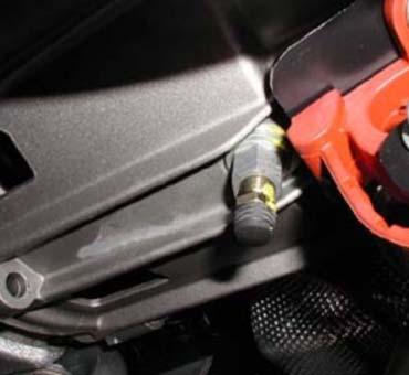
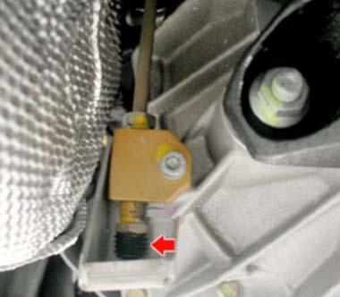
The procedure becomesnecessaryifair bubblesneedtobeeliminatedor following disassemblyofa componentofthe hydraulicclutchcircuit. Bleedingisdonebyusingthe bleedscrewon the clutchhousing.
The procedure involvesbleedingthe system first throughthe bleedscrewlocatednextto the connection block withthe clutchhousing and subsequentlythroughitscounterparton the side (up toassembly14804) or underneath the clutchhousing.
Withthe SD3, start the clutchbleedingprocedure whileaddingoil continuouslyintothe electro-actuatedgearboxoil reservoir, in sucha way thattherecan beno infiltrationofair. The bleedingprocedure endswhenthe oil comingout ofthe bleedscrewno longer containsanyair.
Usethe SD3 torunthe gearboxthrougha sequenceofgearchangestocheckthatthe pumpisworkingcorrectly.
At the end ofthe cycle, checkthe levelofthe oil in the reservoir. Top up ifnecessary.
HYDRAULIC ACTUATOR BLEEDING:
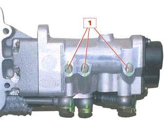
Toaccessthe actuatorbleedscrews, itisnecessarytoremovethe actuator, whileleaving itconnectedtothe electricaland hydraulicsystem.
Removethe actuatorand supportitcorrectlyso astoensuresafeworkingconditions.
Important:
Duringbleeding, supportthe actuatorin such a way thatthe sensorcablesare nottootaut and the hosesare notbenttoexcessivelytight angles. Keepyourhandsawayfromthe actuatorwhilebleedingisin progress.
•Connectthe SD3 diagnosistester tothe diagnosissocket.
•Fromthe mainmenu, go to“Activediagnosis".
•Checkand top up the oil in the reservoirifnecessary.
•Loosenthe threeactuatorbleedscrews (1) bytwocomplete turns.
On completionofthe procedure, executeself-learningofthe engagement and selection thresholdsbychoosingthe “self-learning" functionfromthe “Activediagnosis" menu.
SERVICING OPERATIONS FOR CARS EQUIPPED WITH A GEARBOX MANAGEMENT SYSTEM PRIOR TO SOFAST II
MASERATI M138
HW CFC 201 (SOFAST) up toassembly 12203
Action
Clutchreplacement *
Gearboxreplacement
Hydraulicactuatorreplacement
ReplacementofsolenoidvalvesEV1-23-4-5
MASERATI M144
HW CFC 201(SOFAST)
Clutchbleedingprocedure (clutchbalancingforM138)
Kisspointadjustment
Self-learning
Hydraulicactuatorbleeding
Self-learning
Gearboxactuatorbleeding
Self-learning
Replacementofclutchsolenoidvalve EVF Clutchactuatorbleeding
Pumpreplacement
NCR replacement
Hydraulicactuatorbleeding
Remote loadingofsoftware
Readingofclosedclutchvaluefromnewon the replacedNCR and settingthe valueon the newNCR
Self-learning
Kisspointadjustment
* Clutchreplacementfor pre-SOFAST cars: in thiscase the CLOSED CLUTCH VALUE FROM NEW isfundamental. Beforesaving/confirming, itisimperative toallowthe clutch tobedin brieflybyrunningin the disc.
SERVICING OPERATIONS FOR CARS EQUIPPED WITH SOFAST II GEARBOX MANAGEMENT SYSTEM MASERATI M139 EUROPE version
MASERATI M138
HW CFC 231 (SOFAST II) fromassembly 12204
Action
Clutchreplacement
Gearboxreplacement
Hydraulicactuatorreplacement
ReplacementofsolenoidvalvesEV12-3-4-5
Replacementofclutchsolenoidvalve EVF
Pumpreplacement
NCR replacement
HW CFC 231 (SOFAST II) up to assembly18821
Clutchbleedingprocedure
KissPoint (includesresettingthe clutch degradationindexand configuringthe clutch)
Self-learning
Checkgearchangegrid
Hydraulicactuatorbleeding
Self-learning
Gearboxactuatorbleeding
Self-learning
Clutchactuatorbleeding
KissPoint (includesresettingthe clutch degradationindexand configuringthe clutch)
Hydraulicactuatorbleeding
Remote loadingofsoftware
Readingofclosedclutchvaluefromnewon the replacedNCR and settingthe valueon the newNCR
Self-learning
Kisspoint
SERVICING OPERATIONS FOR CARS EQUIPPED WITH SOFAST III AND SOFAST III+GEARBOX MANAGEMENT SYSTEMS
MASERATI M139 EUROPE version
HW CFC 301(SOFAST III) fromassembly 18822
HW CFC 301(SOFAST III+) fromassembly 21925
MASERATI M139 US version
HW CFC 301 (SOFAST III) up to assembly21925
HW CFC 301 (SOFAST III+) from assembly21926
Clutchbleedingprocedure
CalibrationofDEIS parameters
Clutchreplacement
Gearboxreplacement
Hydraulicactuatorreplacement
ReplacementofsolenoidvalvesEV12-3-4-5
Replacementofclutchsolenoidvalve EVF
Pumpreplacement
NCR replacement
Accelerationsensorreplacement or ABS unitreplacement
KissPoint (includesresettingthe clutch degradationindexand configuringthe clutch)
Self-learning
Hydraulicactuatorbleeding
Self-learning
Gearboxactuatorbleeding
Self-learning
Clutchactuatorbleeding
CalibrationofDEIS parameters
KissPoint (includesresettingthe clutch degradationindexand configuringthe clutch)
Hydraulicactuatorbleeding
Remote loadingofsoftware
CalibrationofDEIS parameters
Self-learning
Readingofclosedclutchvaluefromnewon the replacedNCR and settingthe valueon the newNCR
Autocalibrationofaccelerationsensoroffset Kisspoint
Autocalibrationofaccelerationsensoroffset
Servicing Operations For Cars Equipped With Sofast 4 Gearbox Management System
MASERATI M145 Allmarkets
HW CFC 301 (hardware ECU isidenticaltoSOFAST III)
Iv
Clutchbleedingprocedure
CalibrationofDEIS parameters
Clutchreplacement
Gearboxreplacement
Hydraulicactuatorreplacement
ReplacementofsolenoidvalvesEV12-3-4-5
Kisspoint(includesresettingthe clutch degradationindexand configuringthe clutch)
Self-learning
SuperFastShiftself-learning
Hydraulicactuatorbleeding
Self-learning
SuperFastShiftself-learning
Gearboxactuatorbleeding
Self-learning
SuperFastShiftself-learning
Clutchactuatorbleeding
Replacementofclutchsolenoidvalve EVF
Pumpreplacement
NCR replacement
Accelerationsensorreplacement or ABS unitreplacement
CalibrationofDEIS parameters
KissPoint (includesresettingthe clutch degradationindexand configuringthe clutch)
Hydraulicactuatorbleeding
Remote loadingofsoftware
CalibrationofDEIS parameters
Self-learning
SuperFastShiftself-learning
Readingofclosedclutchvaluefromnewon the replacedNCR and settingofthisvalueon the newNCR
Autocalibrationofaccelerationsensoroffset Kisspoint
Autocalibrationofaccelerationsensoroffset
Note: In anyevent, itisadvisabletoperformthe self-learningprocedures(DEIS; SelfLearning, SuperFastShift, Accelerometer) duringeachservicingoperation.
Introduction
A completely new automatic six speed gearbox (ZF 6HP26) was introduced for the Maserati Quattroportewith automatic transmission, presented in January 2007. Also the Maserati GranTurismouses the same gearbox for the automatic transmission version. The Gearbox is built by ZF and has been developed in cooperationwith Maserati and Bosch (electronic control) to offer the best possible compromisebetween driving dynamics, fuel economy and comfort. The gearbox contains 6 electro-hydraulically controlled gears and a torque converter with lock-up clutch and anti-slip function. The automatic gearbox has a self-adaptive control system that adjusts the type of gearshift strategy, selecting the gear most suited to the driving conditions and driving style. The driver can choose from four different driving modes: Auto Normal, Auto Sport (selectable by pressing the SPORT button), Low-grip /Auto ICE (selectable by pressing the ICE button) and Manual (selectable by shifting the gearshiftlever from "D" to the left). For the Auto Normal and Auto Sport driving modes there are two different types of gearshifting, automatically selected by the gearbox/engine control system based on the driving style (detected through the accelerator pedal and the intensity of lateral and longitudinal acceleration) and the gradient of the road.
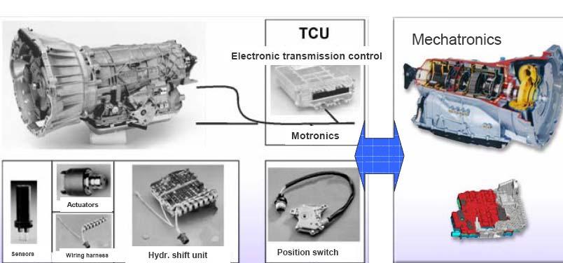
Electronic control:
The electronic control of the gearbox is the “MECHATRONIC”type, meaning that both the hydraulic and the electronic control unit are integrated in a single unit inside the gearbox. This ECU provides dynamic gear ratio selection and has a sequential gear selection program. The adaptive shift strategy memory can be reset by performing the Cycle function with SD3 diagnostic tester. By doing this the gearshiftstrategy will return to its default settings.
Technicalspecifications
Maximum torque:max 600 Nm
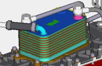
Torque converter: Hydrodynamic converter with regulated clutch
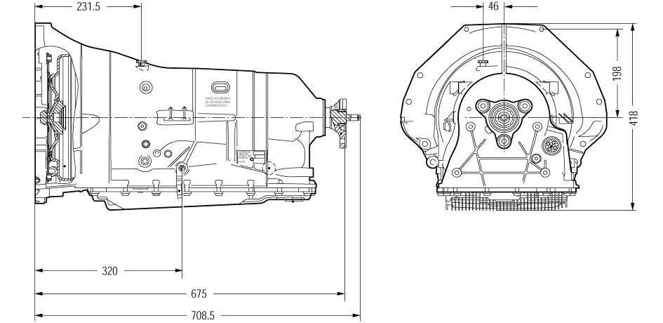
Cooling system: Oil/water exchanger positioned underneath the engine intake manifold
Gearbox oil: Shell M1375.4 ATF (no oil change or refilling required)
Oil quantity:
• Gearbox without converter and oil radiator: 5.8 l
• Torque converter: 3.7 L
• Oil radiator with relative pipes: 0,525 L
Total weight: 142 kg (including oil and gearbox oil radiator)
Gear ratios:
1°: 4.171 Reverse: 3.403
2°: 2.340
3°: 1.521
4°: 1.143
5°: 0.867
6°: 0.691
Parts available for servicing:
•Torque converter (complete unit)
•Mechatronic(complete unit)
•Oil sump
•Oil sump sealing
•Oil filter
•Rubber oil sleeves (4 pieces)
•Rubber oil supply sealing Mechatronic
•Input shaft oil sealing
•Output shaft oil sealing
•Output shaft flange and locking nut
•Oil sealing behind output shaft flange locking nut
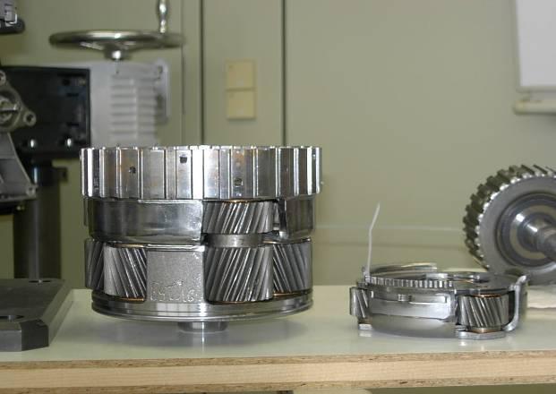
The mechanical transmission devices are made up of planetary gears. The components are driven by an electro-hydraulic system which incorporates the hydraulic and electronic control units in a singe control unit (Mechatronic) fitted on the gearbox. Engine power reaches the transmission by means of a hydrodynamictorque converter with integrated lock-up type clutch (WK).
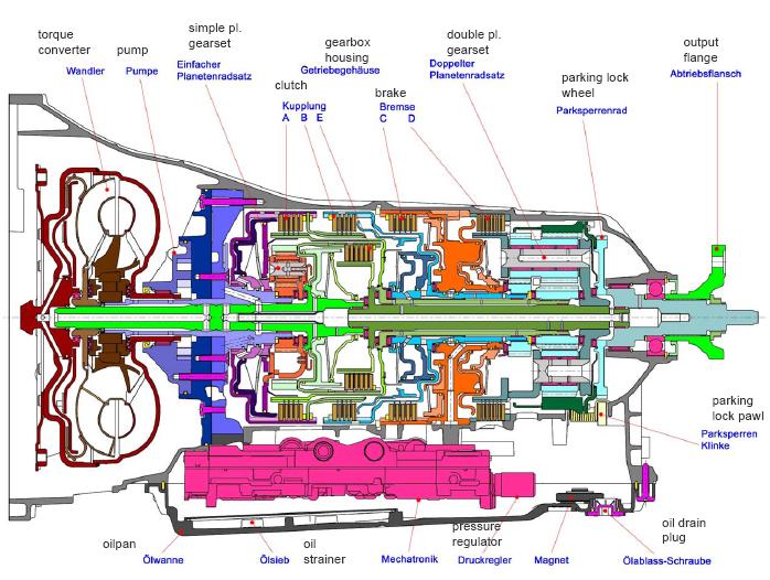
The 6 forward gears and the reverse gear are obtained by means of a double planetary gear (Ravigneaux) and a front-mounted simple planetary gear. The integrated operating modes of the planetary gears are patented (Lepelletier). The individual gear ratios are obtained by deviating the incoming torque flow through the various planetary gear components and by braking others. For this purpose various couplings and brakes are used.
Gear disengagement control logic
A further innovation is the option of automatic disengagement when the vehicle is stationary. This means that the gearbox is disconnected from thekinematic mechanisms when it is in standby (clutch A open). This results in a furtherreduction of fuel consumption.
With the engine idling, the vehicle stationary and the gearshiftlever in “D”, the torque converter transmits a specific torque value that slightly moves the vehicle forward if the brake pedal is not applied. If the brake pedal is applied, the converter is forced to dissipate the power by slowing down the engine RPM, which must be compensated by increasing the minimum torque (by further opening the throttle) until obtaining the correct idling RPM. This results in higher fuel consumption and greater force required on the pedal (for example, to hold the vehicle stationary when stopping at trafficlights or stop signs) which clearly negatively affects driving comfort and handling. Disengagement therefore occurs if a gear is engaged when the vehicle is stationary, depending on different parameters monitored by the gearbox node.
The torque converter is composed of a toroidal-shaped chamber containing two elements: a centrifugal pump connected to the crankshaft and a hydraulic or turbine motor positioned in front of the pump and connected to the gearbox input shaft. The two parts face but do not touch each other and the chamber is filled with low-viscosity oil. The pump is basically a wheel with radiallyarranged blades. When turning, it pushes the fluid towards the outside by effect of the centrifugal force. The fluid also acquires angular momentum. The motor is likewise composed of a bladed wheel. The liquid that the pump pushes to the outside of the device is forced to return to the centre through the turbine blades, driving it so that it rotates.
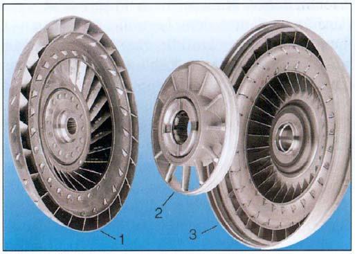
Coated collar (converter with lock-up clutch)
Piston (converter with lock-up clutch)
Converter cover
Converter stub axle
Pump
Turbine Stator
One way clutch
Convertor hub
Flywheel fastening
Once the fluid has returned to the centre, it is again ejected by the turbine thus completing the cycle. Even if the motor section is off, the spiral movementof the fluid produces a twisting moment at the output. The torque converter has, by nature, a slipping feature which causes a loss of energy in the form of heat dispersed by the fluid. To improve energy efficiency, modern converters are equipped with an integrated clutch system which mechanically joins the pump and the motor when the onboardcomputer detects a constant cruising speed. The torque converter (“Trilok" converter) is composed of a pump wheel or impeller, a turbine and a flow reaction component (stator) which multiplies the torque delivered.Another important element for converter operation is the oil used for torque delivery.
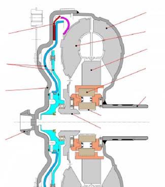
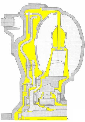
Lock-upclutch
Clutch closed Clutch open
A torque converter lock-up clutch (WK) is a device that makes it possible to eliminate the slipping typical of the torque converter and contributes to optimise fuel consumption. The torque converter with lock-up clutch has a controlled activation and release system. During the adjustment stage, there is a minimal difference between the RPM of the pump and that of the turbine. This has allowed us to reduce the vibrations transmitted by the engine before they reach the transmission: this process can be further boosted by the torsion vibration damper. This principle provides smoother gearshiftingand noise reduction.
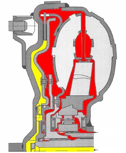
The lock-up clutch can be activated in any gear, but only in conditions of constant driving speed. The lock-up clutch will be disengaged during acceleration or braking.
Parking Lockmechanism
Gear
Pin
Leg spring
Drive collar
Parking lock pawl
Locking cone
Compression spring
Connecting rod
Release spring
Engagement collar
Selection lever
Selection shaft
The parking lock mechanism is a device that stops the vehicle from moving. It is activated by a spring when the vehicle is stationary. A pawl wedges into the parking lock gear teeth, thus preventing the transmission output shaft from rotating. Rear axle torque lock is obtained by means of the output shaft.
Warning: only put the selector lever in the Park position when the vehicle is stationary.
The coupling elements are used for gearshiftingunder load without cutting the power flow.
The clutches A, B and E deliver the engine power to the planetary gears. The brakes C and D buck the movement of other transmission devices in order to obtain the required resistance.
As engagement components, in addition to the torque converter with lock-up clutch (WK), there are three rotary multidisc clutches (A, B and E) and two fixed multidisc brakes (C and D).
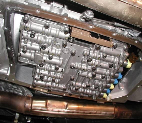
The Mechatronicmodule is composed of a hydraulic selection control unit and an electronic control unit. The hydraulic, electrical and electronic components are incorporated in a single unit. The Mechatronicmodule is positioned near the gearbox oil sump. The main advantages of this module are: fewer electrical connections (which are subject to faults) and automatic calibration of the hardware by the software. This involves: very accurate tolerances, improved gearshift response, enhanced driving comfort, gearshift quality optimisation, improved reliability thanks to the fewer electrical connections and interfaces.
Electrostatic discharge
For any operations on the Mechatronicmodule, take the appropriate precautions in terms of safety, especially to prevent electrostatic discharge (ESD).
The human body, if electrically charged but not properly earthed, becomes an electrostatic “cloud”and may cause damage to the electronic components. It is therefore extremely important to take appropriate precautions, like conductive shoesand ESD protective gloves. To prevent any damage from electrostatic discharge, appropriate precautions must always be taken in the following cases:
•When receiving goods
•In the inspection area of the goods received
•In the workshops, and in the spare parts warehouse even if staying there for only short periods of time
•In the shipping/delivery area
•In the maritime transport or shipping area
•During handling, fitting and removal of the Mechatronicmodule
Keep the packaging material and the ESD protective film so that they can be used when returning the parts removed from the transmission.
Mechatronicunitremoval
In ordertoremovethe mechatronicmodule, carryout the followingsteps:
•Drainthe automaticgearboxoil
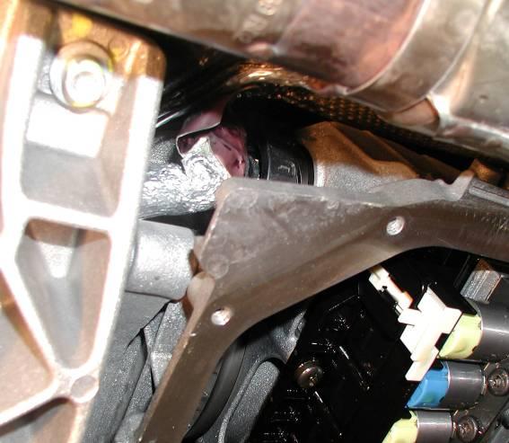
•Disconnectthe wiringharnass connectorfromthe adapter(1)
•Undo the 21 Torxscrews that secure the oil sump on the gearbox and then remove the oil sump and the sealing strip.
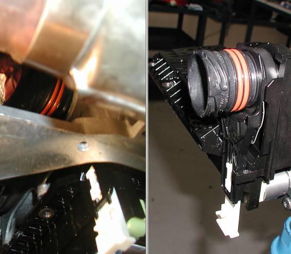
•Pull down the adapter locking lever (2).
•Remove the connector adapter (3) which is pressure-fitted with two O-rings by pulling it out.
•Undo the 10 torxscrews which attach the Mechatronicunit to the gearbox housing to remove the Mechatronic.
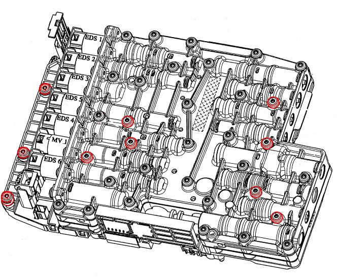
CAUTION! Toremovethe mechatronic, undoonlythe screwsmarkedin red
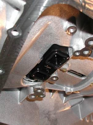
CAUTION!
When the Mechatronicmodule is been refitted, be extremely careful that you correctly fit the gear position selector whit respect to the position sensor.
CAUTION!
When refitting, follow the removal procedures in reverse order and tighten the Mechatroniccontrol unit screws to a torque of 8.0 ±0.8 Nm following the sequence shown in the figure below.
•Position the vehicle as level as possible on the car hoist.
•It is essential that the gearbox oil temperature is between 50°C and 60°C
•It is advisable to check the level when the oil temperature is 55°C
•Connect the SD3 tester and access “SERIAL DIAGNOSTICS”
•Subsequently Select "INDIVIDUAL ECU DIAGNOSTICS”
•Then select the vehicle and the ECU involved.
•Wait for the ECU and serial number to be loaded.
•Select “PARAMETER ENVIRONMENT” and then “GENERAL PARAMETERS 1”.
•Then access the vehicle data and read the “TRANSMISSION OIL TEMPERATURE” value.
•Starting the checking procedure:
•Check the oil temperature : If the temperature is above 60°C, wait until it cools down.
•If the temperature is below 50°C, move the gearshift lever to REVERSE and then to DRIVE, holding it in each position for at least 3 seconds.
•Always keep the wheels locked.
•Check the temperature with the SD3 tester; if it has risen to about 55°C, turn off the engine and then search for the gearbox ECU errors and delete them.
•Start the engine and let it run in idle, then unscrew the oil filler cap (1).
•The sump is filled “to the brim”with oil, therefore if oil spills out when the cap is unscrewed, no top-up is necessary.

•WITH THE ENGINE OFF: position the tool in the filling hole on the sump and pump in oil until it starts spilling out.
•WITH THE ENGINE IDLING: continue filling with gearbox oil until it starts spilling out
•Keeping the engine running, connect the SD3 tester and access “SERIAL DIAGNOSTICS”
•Subsequently Select "INDIVIDUAL ECU DIAGNOSTICS”
•Then select the vehicle and the ECU involved.
•Wait for the ECU and serial number to be loaded.
•Select “PARAMETER ENVIRONMENT” and then “GENERAL PARAMETERS 1”.
•Then access the vehicle data and read the “TRANSMISSION OIL TEMPERATURE” value.
•Check that the gearbox oil temperature is between 50°C and 55°C.
•Continue filling with oil until it starts spilling out.
•Tighten the oil filler cap (1) to a torque of 60 Nm
CAUTION! EXCLUSIVELY USE OIL TYPE SHELL M1375.4 ATF
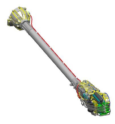
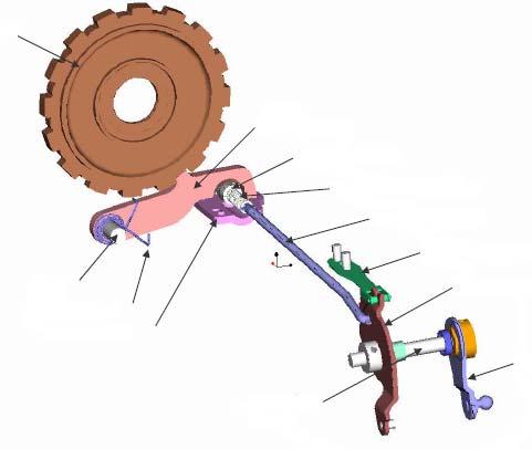
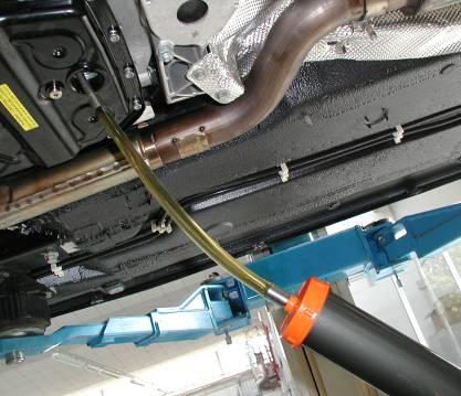
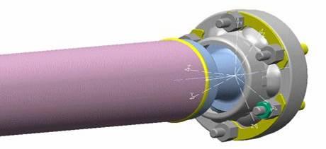
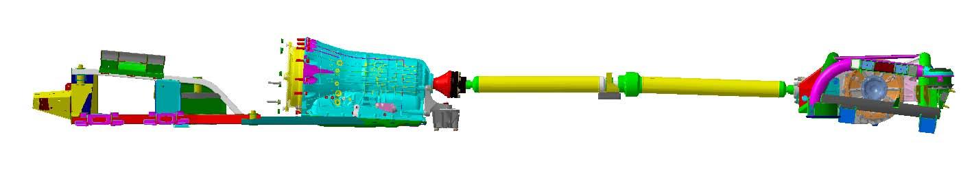
Modular TransmissionShaft
For vehicles fitted with the ZF automatic transmission, a new modular transmission shaft is applied. The shaft needs to be balanced after removing one ormore components of the transmission system. This is done using tool DSE1, by applying balancing weights on the differential coupling flange.
The modular transmission shaft was chosen for technical reasons, due to the different alignment of the engine axis with respect to the rear differential axis, which makes the homokineticalmotion transmission impossible.
Modular Transmission shaft balancing procedure
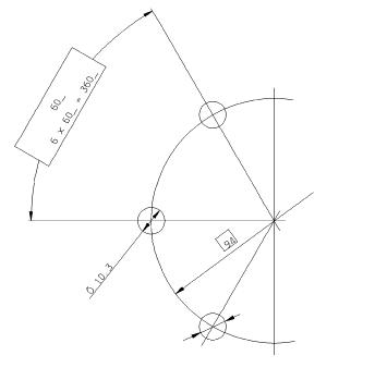
The balancing kit contains a set of nuts of known weight with which the balancing weight calculated by the instrument must be approximated. As these nutswill be fitted on the retaining bolts of the transmission shaft coupling flanges, the bolts need to be clearly identified so that the fitting positions indicated by the instrument are respected. Actually, unlike wheel balancing, where the balancing weight can be fittedin any position along the perimeter of the wheel rim, in this case there are six fixed positions on the rear of the shaft fastening flange.
The instrument thus divides the result into weights equivalent to the theoretical balancing weight. These weights must be approximated with the available nuts, obtaining an overall effect equivalent to that of one balancing weight.
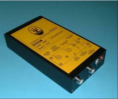
To perform the test, you need to use the following instruments together with the SD3 diagnostic tester: DSE1 or DSE2
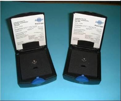
The kit contains two B&K 4508 accelerometers, but only one of the two shall be used for the balancing procedure. The cables required to connect to the DSE1/DSE2 instrument are also provided in the kit.
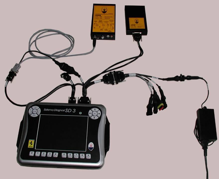
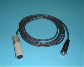
Prepare the SD3 tester connecting it to the DSE1/DSE2 instrumentand the DC/DC converter, as described below.
1.SD3 connection
2.SD3 connection
3.CAN connector
4.V BATT connector
5.SD3 CBL 07
6.Power supply
7.DC/DCconverter(To beusedonlyin case the EOBD connection isnotused)
8.DSE1/DSE2 instrument
9.Greyconnectorcable RS232 –DSE1/2
10.Black connectorcable SD3 –DC/DC converter
Preparing the vehicle
Position the vehicle on a hoist.
Remove the two rear wheels and position the vehicle on mounts which must be approx. 18 –20 cm high.
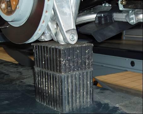
These mounts must hold the vehicle level and compensate for the absence of the wheels. Provisionally use the rubber bushings positioned underneath the hub carrier. Specific mounts of predefined height are being tested, and these will rest in a less delicate area to also facilitate levelling the vehicle. Cut some stickers 0.5 cm wide and 4 cm long out of a reflective adhesive sheet of paper.
Apply the sticker (A) on the transmission shaft. The sticker must be positioned in correspondence to the flange stud bolt marked with number 1 (B).
If present, remove all the balancing weights applied on the flange stud bolts before starting the balancing procedure.
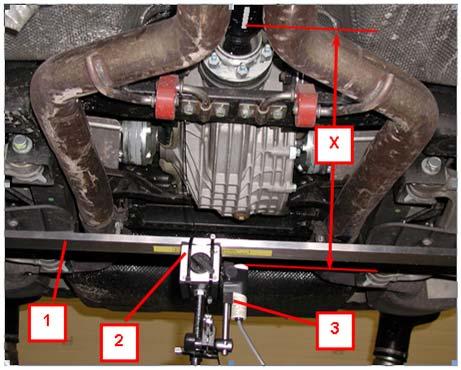
Positioning the RPM sensor
Position the RPM sensor (3) so that it is fully perpendicular to the ground and in line with the transmission shaft (X), at a distance of approximately 50 cm from the shaft.
To do this, you can, for example:
Fit a mount (1) equipped with a base (2) to support the speed sensor (3). The material is not provided in the kit and must therefore be purchased locally.
Securely fasten the sensor on the relative mount and position it as described above.
CAUTION! Once positioned, the sensor must not be moved for the entire duration of the balancing procedure so as not to alter the reference point for the instrument.
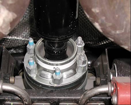
Positioning the accelerometer
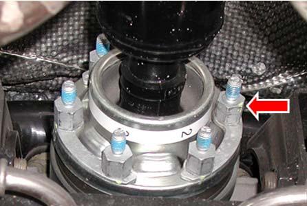
The B&K 4508 accelerometer must be fitted underneath the differential near the transmission shaft (Fig. 2)
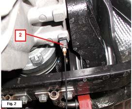
Using HEPTANE, remove any residues of glue or grease from the flat surface on the differential where the accelerometer holder will be positioned.
Apply epoxy glue in the centre of the flat surface of the accelerometer holder (1). Position the accelerometer holder (1) on the differential and hold it down for about 20 seconds, so that it adheres properly.
Fit the accelerometer (2) on its holder (1).
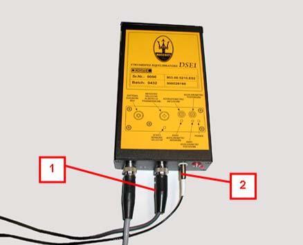
Connecting the DSE1/DSE2 components:
Connect the speed sensor (1) cable and the accelerometer (2) cable to the DSE1/DSE2.
Balancing cycle with SD3. (Phase I)
Start the SD3 tester, access the “SERIAL DIAGNOSTICS”environment and then “INDIVIDUAL ECU DIAGNOSTICS”.
Select “TOOLS”and then “ALL”.
Select the item relating to transmission shaft balancing for the vehicle M139EV07.
A page will be displayed showing the following options.
DISPLAY DATA
ACTIVATE BALANCING
SET TEST WEIGHTS
UPDATE CARD
EXIT
Select “UPDATE CARD”.
A page will appear showing the software version installed on SD3and on DSE1/DSE2. If the software version of DSE1/DSE2 does not coincide with the version installed on SD3, update it by selecting “YES”. If this is not the case, select “NO”and return to the home page.
Select “ACTIVATE BALANCING”.
With the help of a second operator seated in the vehicle, start the engine, check that the EPB (Electronic Parking Brake) is disengaged and manually deactivate the MSP function. Select “SEQUENTIAL MANUAL”gearbox operation.
Balancing cycle with SD3. (Phase II)
The shaft balancing procedure is divided into three phases:
INITIAL RUN
TRIAL RUN
FINAL RUN
All three phases are guided “step-by-step”by the SD3 program. We recommended that you carefully follow the instructions displayed on the SD3.
Initial Run
The INITIAL RUN phase is a data acquisition phase performed by the tester. The tester measures the shaft unbalance and stores the data as a basis for comparison of the subsequent measurements
For data acquisition, the transmission shaft must run at a speedbetween 2850 –3150 RPM (equivalent to 2800 engine RPM read on the instrument panel when 5th gear is selected) and must be kept at this speed throughout the data acquisition phase.
To easily reach the required RPM, set “SEQUENTIAL MANUAL”operation to progressively arrive at engaging 5th gear.
Hold the accelerator pedal depressed until reaching the requiredRPM values, keep them constant throughout the data acquisition phase and wait for the result.
Initial Run OK
If the data acquisition phase is successfully completed, it means that the tester has been calibrated using an unbalance value that does not exceed the maximum value set in the tester.
Subsequently, you automatically go to the TRIAL RUN phase.
Initial Run NOT OK
If the data acquisition phase is not completed successfully, it means that the tester has measured an unbalance value that exceeds the maximum value set in the tester.
The system will automatically prompt you to position a rebalancing weight of 4.5 grams on the flange stud bolt marked with number 1 (Position 1).
Repeat the INITIAL RUN phase.
If the unbalance value is still not compensated, the system willautomatically prompt you to move the rebalancing weight from Position 1 to Position 2 and torepeat the INITIAL RUN phase. This process will be repeated (going through the various positions from 1 to 6) until the correct position for the rebalancing weight is found.
Once the correct position for the rebalancing weight has been found, you will automatically go to the TRIAL RUN phase
CAUTION. If the correct position for the rebalancing weight is not found, remove the rebalancing weight of 4.5 grams and repeat the cycle using a weight of 7.5 grams.
Once the correct position for the rebalancing weight has been found, you will automatically go to the TRIAL RUN phase
CAUTION. If the correct position for the rebalancing weight is not foundeven when using the weight of 7.5 grams, carefully check all the components connected to the transmission shaft (rear differential, axle shafts etc.).
When you have inspected all the mechanical components, repeat the entire cycle with the rebalancing weight of 4.5 grams (7.5 grams if necessary).
If the procedures fails again, contact the Maserati Technical Service Department
CAUTION!
Should the adhesive tape bearing the corresponding number for each stud bolt not be present, it is important to assign the correct numbering: affix the number 1 in correspondence to a stud bolt and then the other numbers with clockwise orientation.
Trial Run
This is the phase where the tester reads the various positions to correct the unbalance. The TRIAL RUN phase consists of two different actions, dependingon whether or not the INITIAL RUN is completed successfully the first time it is performed.
a) INITIAL RUN OK on first attempt. The system automatically prompts you to position a reference weight of 4.5 grams in Position 1 b) INITIAL RUN NOT OK on first attempt. The system automatically prompts you to position a reference weight of 4.5 grams in the position where the rebalancing weight is present
Start the TRIAL RUN procedure from the SD3.
CAUTION. In condition (a) described above, the reference weight of 4.5 grams in Position 1 might cause an excessive unbalance not readable by the tester.In this case, the tester will automatically prompt you to position the same reference weight in Position 4. Repeat the TRIAL RUN phase with the weight in Position 4.
The TRIAL RUN procedure ends with a page displaying a table:
A: Ideal value (information only)
B: Number of the flange stud bolt where you have to position the first correction weight (whose value in grams is indicated in the next column)
C: Number of the flange stud bolt where you have to position the second correction weight (whose value in grams is indicated in the next column)
Remove the reference weight of 4.5 grams previously positioned. Apply the correction weights as described in the table. Click on NEXT to go to the “FINAL RUN”phase.
Final Run
This is the phase where the tester reads and assigns the weightsfor unbalance correction. Continue the procedure and follow the on-screen instructions. Continue applying the correction weights as described in the tables that will be displayed.
Continue until the tester indicates an IDEAL VALUE in the table lower than or equal to 2.1 grams Having reached the correct value, click on “EXIT”and confirm to print the test.
Important
The procedure does not end automatically but only by selecting “EXIT”. The procedure is complete when the transmission shaft is balanced.