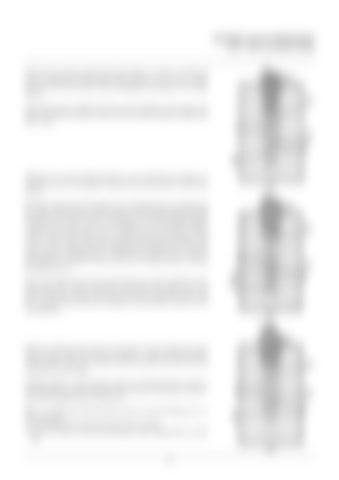
INCHING VALVE OPERATION (TH 7 Valve on Brake Pedal)
With the foot off the inching pedal, the tappet 1 is fully in and the oil passes unhindered between port P (pilot pressure in) and port A (pilot pressure out). The oil flows freely through the opening 3 in the slide valve 2. The pilot pressure, injected into the control cylinder of the pump cam plate, is therefore identical to that which would be obtained without this TH 7 valve.
With the foot on the inching pedal for a slow approach, the tappet 1 is partially out; the oil passage is calibrated by the opening 3 in the slide valve 2. The pilot outlet pressure through port A will therefore be controlled and the value of this pressure will be constant. If the pilot pressure entering through port P were to increase, as this pressure would be applied to the section S of the slide valve 2, the springs 4 and 5 would be slightly compressed and the slide valve 2 would move in the direction of the arrow F. This would reduce the oil passage through the opening 3 and in turn create a drop in pressure between port P and port A. The pilot outlet pressure through port A is therefore controlled and the value of this pressure is constant whatever the level of pilot pressure entering through the port P. This means that the pressure injected into the control cylinder of the pump cam plate will be constant, and therefore the angle of the cam plate will also be constant. This allows the truck to approach slowly and at a constant speed selected according to the pressure exerted on the inching pedal.
With the inching pedal pressed to the limit of travel before the truck brake control comes into force, the tappet 1 is fully out (this position with the slide valve out is retained when the pedal at the limit of travel controls the truck brakes). With the tappet 1 in this position, there is no pilot pressure at port A, and therefore no pressure in the control cylinder of the pump cam plate. The pump displacement is therefore nil. NB : It is understood that the pilot pressure leaving through port A is always guided: • on the one hand towards the pump control cylinder, • and on the other towards the hydraulic motor displacement control unit.
99

