7 minute read
INSTALLATION OF APERSONNELWORK PLATFORM


cover specific, controlled test conditions, which are extremes, and which are not intended to be achieved during normal worksite operations. The following specifications are provided only as information to the operator, and must not be used as a guideline for operating the telescopic handler. For safe operation, always follow the instructions and warnings provided in this manual.
1.DO NOT place or retrieve loads on a up or down slope or grade that exceeds 7% or 4o grade.
2.DO NOT travel up or down a grade or slope that exceeds 22% or 12o grade while loaded.
3.DO NOT place or retrieve loads on a side hill with a slope or grade that exceeds 12% or 7o grade.
Regardless of the terrain or position of the wheels, the FRAME MUST BE LEVEL, as indicated by the frame angle indicator on the ROPS crossmember.
4.DO NOT travel across a side hill that exceeds 18% or 10o grade. Regardless of the terrain or position of the wheels, the FRAME MUST BE
LEVEL, as indicated by the frame angle indicator on the ROPS crossmember. The attachment tool
MUST be maintained at the “carry” position, with the boom fully retracted, and attachment tool at minimum ground clearance.
When ascending or descending grades in excess of 5% or 3o, the machine should be driven with the load upgrade. An unloaded machine should be operated on all forward grades with the load handling attachment tool downgrade, tilted back if applicable, and raised only as far as necessary to clear the road surface. Avoid turning if possible and use extreme caution on grades, ramps or inclines. Normally travel straight up and down.
WARNING
DO NOT level the frame with the boom raised or extended. Level the frame ONLY while stopped, with the boom fully retracted, and the attachment tool raised just enough to clear the ground.
Traffic Flow Patterns
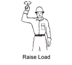
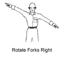
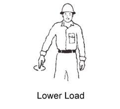
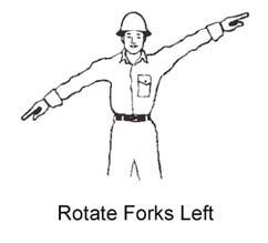
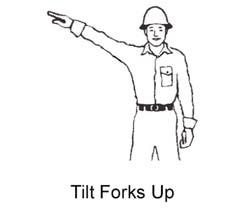
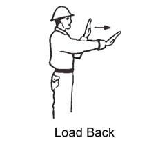
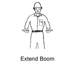
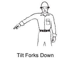
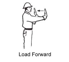
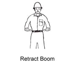
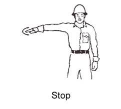
For safety, know and understand the traffic flow patterns of your jobsite and the Telescopic Handler hand signals. Use signal persons and make sure you can see the signal person and acknowledge the signals given. Refer to the safety hand signal illustrations on the next page. The backup alarm automatically sounds when the travel lever is in Reverse. Care should be taken when down shifting or reversing because damage to the transmission can occur if shifting is forced or attempted while traveling. When ramps must be used in transporting loads with the machine, the following shall be the minimum widths for safe travel:
Compacted dirt, gravel, etc. - 12 ft. (3.6 m) Woodboard, concrete, etc. - 10 ft. (3 m)
Permanent aisles, roadways, passageways, floors and ramps should be marked or defined in some fashion. Permanent or temporary protrusion of loads, equipment, material and construction facilities into the usual operating area should be guarded, clearly and distinctively marked, or clearly visible. Maintain a safe distance from the edge of ramps, platforms and other similar working surfaces. Controlled lighting of adequate intensity should be provided in operating areas. Where operating conditions indicate, the operator/user is responsible for having the machine equipped with lights. Provision should be made to prevent trucks, semi-trailers and railroad cars from being moved during loading and unloading. Wheel stops, parking brakes, or other positive means should be used to prevent movement during loading and unloading. DO NOT move railroad cars or trailers with the Telescopic Handler.
DO NOT use the boom and attachment for leverage to push the machine out of mud. IMPORTANT: DO NOT lower boom at high engine speed when attachment tool is at maximum rearward tilt. Damage to slave cylinders may result.
GENERAL LOAD HANDLING
NEVER attempt to work controls except from the operator’s seat. NEVER jerk or use fast movements. Avoid sudden stops, starts and changes in direction. Operation of the hydraulic system depends on engine speed and the distance the controls are moved. When operating these controls it is important to develop a technique called “feathering.” Feathering the control means starting the desired motion by moving the control a small amount away from neutral. Then, after movement has started, the control can be eased to full movement. Use the same feathering technique to stop the motion.
Load Capacity and Reach
The machine has flip-charts in the operator’s station that provide, at a glance, the capacity limits at various positions of attachment tool extension and elevation. A set of the load zone charts is reproduced at the end of this manual for reference.
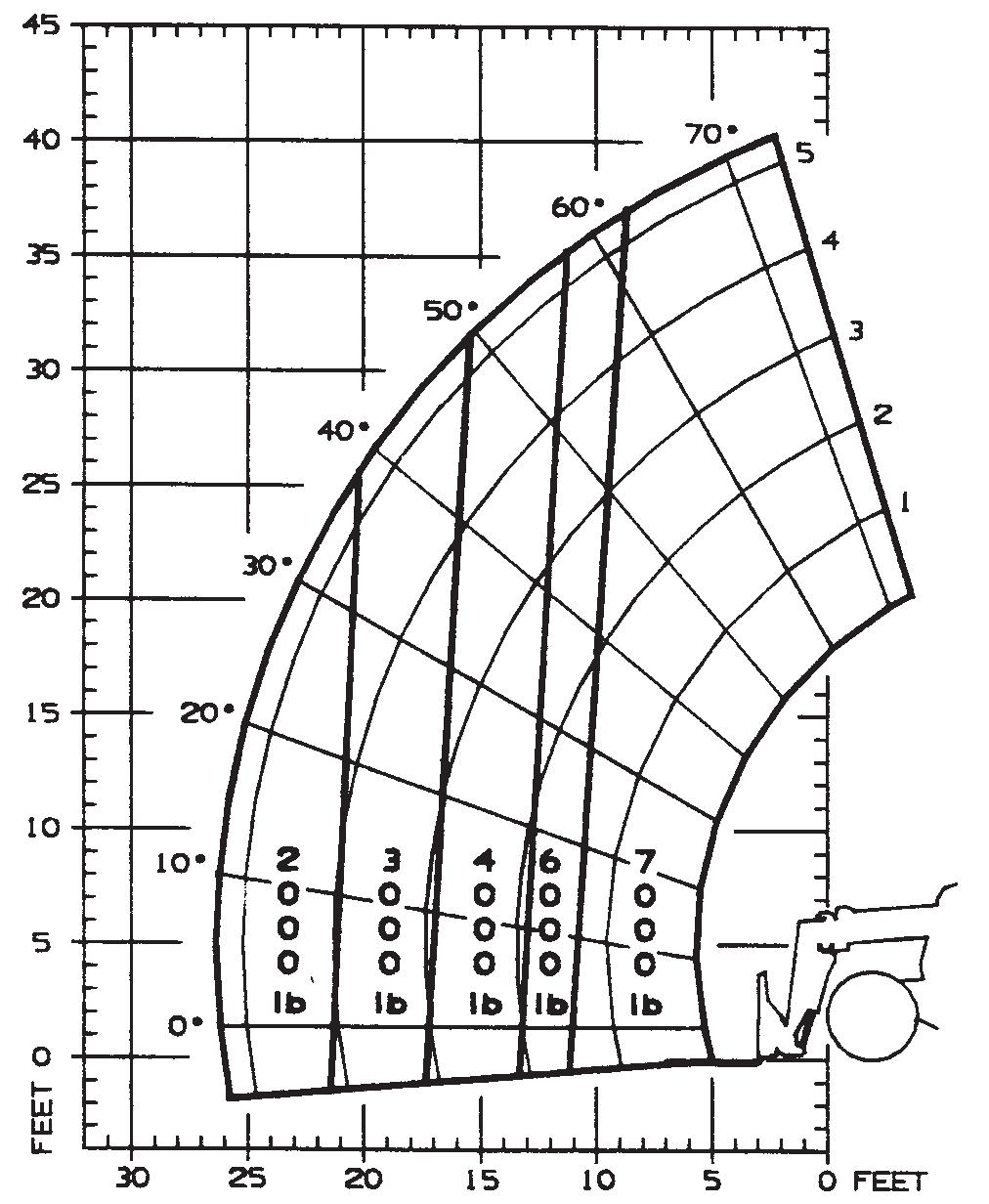
A typical load zone chart is shown on this page. The scale on the left indicates height in feet above the ground level. The scale on the bottom shows the distance in feet from the front of the machine. The arc lines noted by the numbers “1” through “5” correspond
WARNING
Excessive speed can be hazardous. ALWAYS exercise caution and good judgement while operating the machine. The Mandatory Work Platform Safety Rules must be adhered to at all times while elevating personnel. ALWAYS maintain a safe distance from electric power lines and avoid contact with any electrically charged conductor and gas line. It is not necessary to make direct contact with a power line for power to ground through the structure of the machine. Keep the boom and load at least 10 ft. (3 m) from all power lines. Accidental contact or rupture can result in
electrocution or an explosion. Contact the “Call Before You Dig” referral system number at 8-1-1 in the U.S., or (888) 258-0808 in the U.S. and Canada, to locate any underground utility lines BEFORE starting to dig. Keep all body parts inside the operator’s station while operating the machine. BE SURE of clearance for the attachment tool when turning, working around buildings, etc. Turning corners too fast can tip the machine, or cause a load to tip off the attachment. Sudden slowing or stopping of the machine may cause the load to fall off the attachment tool.
Be certain you can control both speed and direction before moving. Always place the machine in neutral and set the parking brake before raising or extending the boom. NEVER drive the machine up to someone standing in front of the load.
NEVER leave the operator’s station without first lowering the attachment tool to the ground. Set the parking brake, place controls in neutral, shut off engine and remove the key. AVOID parking the machine on a slope, but if necessary, park across the slope and block the tires.
with the position extension markers on the operator side of the intermediate boom section.
The following example illustrates proper use of the load zone charts for the Telescopic Handler: Example: The operator, using a standard carriage attachment tool without outriggers, wants to raise a 3000 lb. load 20 feet high, and can only get to within 15 feet of the load placement point. Can this be done within the capacity of the machine? Analysis: See “Typical Load Zone Chart” above. Projecting up from the 15-foot reach mark on the horizontal axis to intersect a line through the 20-foot height mark on the vertical axis shows that up to a 4000 lb. load can be placed in that zone. During placement, the operator should observe when the arc reference number “4” on the boom is visible and stop. The operator knows the maximum safe extension distance with the 4000 lb. load has been reached.
LIFTING ATTACHMENT TOOL
HEIGHT ABOVE GROUND
BOOM EXTENSION MARKERS
DISTANCE LOAD IS EXTENDED
Typical Load Zone Chart APPLICATIONS
Picking Up the Load
Inspect the load before picking it up. If it appears unstable, DO NOT attempt to move it. DO NOT attempt lifting double-tiered loads, or straddling sideby-side pallets one on each fork. NEVER add extra unauthorized counterweights to the machine. Approach the load squarely and slowly with the
machine straight and level. Adjust the space between forks, if necessary. Engage the load equally on the forks until the load touches the carriage backrest. Tilt the forks back to position the load for travel.
WARNING
NEVER exceed the rated operating capacity of the Telescopic Handler as shown on the load zone charts.
Carrying the Load
If the load obstructs the view, have a helper direct the operator. Maintain ground speed consistent with ground conditions and which permit stopping in a safe