12 minute read
CHANGING ATTACHMENT TOOLS


Chapter 4
OPERATION AND ADJUSTMENTS
GENERAL INFORMATION
CAUTION
BEFORE starting the engine and operating the Telescopic Handler, review and comply with ALL safety recommendations in the SAFETY chapter of this manual. Know how to STOP the machine before starting it. Also, BE SURE to fasten and properly adjust the seatbelt.
ENGINE BREAK-IN
Your new engine does not require extensive “breakin.” However, for the first 100 hours of operation: Allow the engine to idle for a few minutes after every cold start, DO NOT idle the engine for long periods of time, DO NOT operate the engine at maximum power for long periods of time, and check the oil level frequently, and replenish as necessary with the oil specified in the engine manual. John Deere engines use a “break-in” oil for the first 100 hours of operation. After the first 100 hours of operation, change the oil and replace the oil filter. Consult the Lubrication chapter or the engine manual for the type of oil to use in the engine. Refer to the Service and Storage chapter for the proper service intervals.
PRE-START INSPECTION
Every Pre-start Inspection must include more than checking the fuel and oil levels. It is the operator’s responsibility to inspect the machine before the start of each workday. It is also a good practice to personally inspect any machine you are assigned to use, even if it has already been checked and put into service by other personnel. The most efficient method of checking a machine is by conducting a “Walk-Around Inspection.” The Pre-start Inspection and Daily Maintenance Handbook provided with your Telescopic Handler can be used as a guide for the “Walk-Around Inspection.”
BEFORE STARTING ENGINE
Before starting the engine and running the machine, refer to the Indicators and Controls chapter and familiarize yourself with the various operating controls, indicators and safety features.
STARTING THE ENGINE
Before mounting the operator’s compartment, walk completely around the machine to be sure no one is under, on, or close to it. Let others in the area know you are going to start the machine, and wait until everyone is clear.
WARNING
ALWAYS fasten the seatbelt BEFORE starting the engine. Leave the park brake applied until the engine is running and you are ready to operate the machine.
The following procedure is recommended for starting the engine: 1.Grasp the hand holds and step up into the operator’s compartment. 2.Adjust the seat and fasten the seatbelt. 3.Check that all controls are in their “neutral” positions, except the parking brake switch, which should be in the “ON” position. 4.Adjust the position of the steering wheel tilt console to provide comfortable handling. 5.Turn the keyswitch to “ON” position and press the start button. If the button is released before the engine starts, turn the keyswitch to “OFF” position, and allow the starter to stop before attempting to start the engine again. IMPORTANT: Crank the starter until the engine is started. If the engine fails to start within 30 seconds, return the key to the “OFF” position, wait two minutes, and try to restart the engine. Cranking the engine for longer than 30 seconds will result in premature failure of the starter.
6.After the engine starts, allow a 1-2 minute warmup time before attempting to operate the controls. 7.Check that indicators are in their normal operating condition. 8.Verify that there are no fuel, oil or engine coolant leaks, and no abnormal noises or vibrations.
COLD STARTING PROCEDURES
The engine is equipped with a block heater. This block heater or other starting aid is required for starting in temperatures below 32°F (0°C). See your Gehl dealer for additional starting aids.
For proper use of starting aids, check the instructions in the engine manual.
If the battery becomes discharged and has insufficient power to start the engine, jumper cables can be used for starting assistance. Refer to the jump starting instructions in the Service and Storage chapter of this manual for safe jump-start procedure.
STOPPING
The following procedure is the recommended sequence for stopping the machine: 1.Bring the machine to a stop on a level surface.
Avoid parking on a slope, but if necessary park across the slope and block the tires. 2.Fully retract the boom and lower the attachment to the ground. Idle the engine for gradual cooling. 3.Place controls in neutral. Set the parking brake switch to “ON.” 4.Turn the keyswitch key to the “OFF” position.
Remove the key. 5.Unfasten the seatbelt, and grasp the hand holds while climbing out of the operator’s compartment.
FIRST TIME OPERATION
Make sure the engine is warm and then go through the following procedures. Place the travel lever in a speed range and in Forward or Reverse. Turn off the parking brake switch and move slowly, while testing the steering and brakes. Stop and operate all boom functions and frame leveling controls, checking for smooth responses.
Apply the service brakes, and move the travel lever to the opposite direction (forward or reverse).
Shifting to the next higher gear may be done at any engine speed while the machine is in motion.
DO NOT overspeed the engine when down shifting. Allow the machine to slow down before shifting to the next lower gear.
CAUTION
Be sure the area being used for test-running is clear of spectators and obstructions. Initially, operate the machine with an empty attachment tool. ENGINE SHUTDOWN PROTECTION
The engine is equipped with a WARNING and SHUTDOWN feature that warns users of low engine oil pressure and of high engine coolant temperature. If the problem is not corrected, the engine power will be reduced automatically, or the engine will shut down.
Engine Oil Pressure
There are two low oil pressure protection features: Low Oil Pressure WARNING, and Low Oil Pressure SHUTDOWN.
At the Low Oil Pressure WARNING set-point, the warning lamp in the engine override switch will flash, and a slow engine power derate will begin. But if the oil pressure rises above the Low Oil Pressure WARNING set-point, power will slowly increase until the engine is back to full power. The lamp will continue to flash until the power has returned to normal, even if the fault condition has been corrected and the recovery is in process. At the Low Oil Pressure SHUTDOWN set-point, the warning lamp in the engine override switch will light continuously, and a fast engine power derate will begin. If the oil pressure does not rise above the SHUTDOWN set-point within 30 seconds, the engine will shut down. However, if the oil pressure rises above the Low Oil Pressure SHUTDOWN set-point within 30 seconds, then the power derate speed will revert to the Low Oil Pressure WARNING speed of reaction.
There are two coolant temperature protection features: High Coolant Temperature WARNING, and High Coolant Temperature SHUTDOWN. At the High Coolant Temperature WARNING setpoint, the warning lamp in the engine override switch will flash, and a slow engine power derate will begin. But if the coolant temperature drops below the High Coolant Temperature WARNING set-point, the power will increase slowly until the engine is back to full power. The lamp will continue to flash until the power has returned to normal, even if the fault condition has been corrected and the recovery is in process. At the High Coolant Temperature SHUTDOWN setpoint, the warning lamp in the engine override switch will light continuously, and a fast engine power derate will begin. If the coolant temperature does not drop below the SHUTDOWN set-point within 30 seconds, the engine will shut down. However, if the coolant temperature drops below the High Coolant Temperature SHUTDOWN set-point within 30 seconds, then the power derate speed will revert to the High Coolant Temperature WARNING reaction speed.
PARKING BRAKE
NOTE: The parking brake mechanism within the front axle is not designed for, and not intended to be used as, the primary means of stopping movement of the machine. Hydraulic braking provided through the service brakes within the axle is the primary means for stopping movement.
The proper sequence for correct machine operation is to always engage the parking brake switch before shutting off the engine, and to disengage the brake ONLY after the engine is running. In an emergency however, if it becomes necessary to stop movement, activate the parking brake switch to “ON.”
CHANGING ATTACHMENT TOOLS
The Telescopic Handler boom nose will accept Quick Attach System Manitou attachment tools.The Quickattach System has a quick-release hookup and locking mechanism for mounting framing-type or masonry type attachment tools to the boom nose.
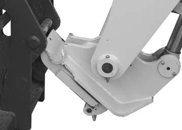
Attachment Tool Quick-Attach System Tilted Forward for Hook up
Attachment Tool Shown Locked to Quick Attach System
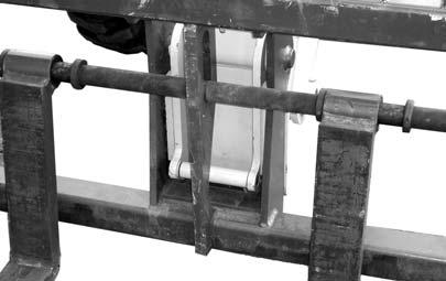
To pick up an attachment tool, proceed as follows: 1.Raise the boom slightly and extend it 2 or 3 feet (600 to 900 mm) for better visibility. Tilt the tool carrier forward. 2.Align the tool carrier squarely with the back of the attachment tool. 3.Slowly extend the tool carrier and lower the hooks under the attachment tool hookup bar. 4.Tilt the tool carrier back so that the lock plate engages the attachment tool. This secures the attachment tool to the Dynattach System. 5.For an attachment tool with auxiliary hydraulics, connect hoses to the quick-connect connectors on the boom nose.
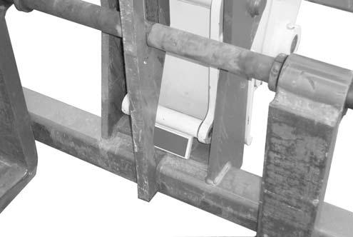
Attachment Tool Shown Unlocked for Release from Quick Attach System
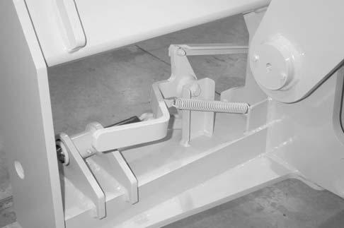
Quick-Attach System Detaching Detail
Detaching the Quick-attach System
To detach the attachment tool, proceed as follows: 1.Raise the boom slightly and extend it 2 or 3 feet (600 to 900 mm) for better visibility. Lower the boom until the attachment tool is approximately 12” (300 mm) off the ground. 2.Roll back the carrier as far as it will go. When the carrier is rolled back completely, perform the
MANDATORY SAFETY SHUTDOWN PRO-
CEDURE (Safety chapter p. 9). 3.With the engine off, leave the operator’s station and manually raise the lock spring and flip the lock plate up and outward at least 180° so that it is in position to re-lock onto the next attachment tool. 4.Tilt the tool carrier forward to allow the attachment tool to roll out, then lower the boom so that the hook ears clear the hookup bar on the attachment tool. NOTE: One side of the lock plate has a bright red decal to indicate the unlocked position.
5.If the attachment tool has auxiliary hydraulics, disconnect the hoses from the quick-disconnects on the boom nose. 6.Start the engine and roll the tool carrier forward.
Slowly back the machine until the attachment tool is free from the boom nose. To pick up a bucket or material handling carriage tool, proceed as follows: 1.Rotate the lock lever completely to the left (counter-clockwise, as viewed from the operator’s station) to fully retract the lock pins. 2.Raise the boom slightly and extend it 2 or 3 feet (600 to 900 mm) for better visibility. Tilt the tool carrier forward. 3.Align the tool carrier squarely with the back of the attachment tool. 4.Slowly extend the tool carrier and tilt it forward until the support pins on each side are in-line with and slightly below the hookup ears on the back side of the attachment tool. 5.Slowly drive the machine forward, and, at the same time, roll the tool carrier back to engage the hookup ears on the attachment tool. Also, establish proper alignment of the carrier lock pins to the attachment tool. 6.Stop forward travel when the hookup ears are engaged, but continue to roll the tool carrier back to pick the attachment tool off the ground. When the tool carrier is rolled back completely, perform the MANDATORY SAFETY SHUTDOWN
PROCEDURE (Safety chapter p.9). 7.With the engine off, leave the operator’s station, and swing the lock lever completely to the right (clockwise, as viewed from the operator’s station) to fully engage the lock pins. 8.For an attachment tool with auxiliary hydraulics, connect the hoses to the quick-connect connectors on the boom nose.
LOCK LEVER
® Carriage Quick-attach System
WARNING
To prevent unexpected and undesired attachment tool release from the boom carrier, be sure to properly secure the quick-release lock pins by rotating the lock lever all the way to the right or inside. Modifications, alterations to, or use of attachment tools not authorized by Manitou N.A. Company can void the warranty and cause machine damage, and may result in serious personal injury or death.
SELF-LEVELING
The machine has a hydraulic self-leveling feature. This feature is designed to keep the attachment tool level while the boom is being raised.
GENERAL MACHINE OPERATION
Check the Telescopic Handler to be sure all systems are in good operating condition. Perform the following steps before starting the machine for the first time each day. 1.Check the engine oil, coolant, transmission oil and hydraulic oil levels. 2.Make sure weekly lubrication has been done. 3.Visually inspect for leaks, broken or malfunctioning parts. Make sure all caps, covers and safety shields are in place. 4.Check tires for cuts, bulges, nails, correct pressure, loose wheel nuts, etc. 5.Inspect the work area. Make sure you know where you will make load pickups, lifts, and turns. Look over the terrain of the jobsite for holes, obstacles, slippery surfaces, soft or deep mud. 6.Check clearances of ramps, doorways and passage ways. Check overhead clearances if you will travel and place loads near power or telephonelines. If the machine is found to be in need of repair or in any way unsafe, or contributes to an unsafe condition, the matter shall be reported immediately to the user’s designated authority. The machine should NOT be operated until it has been restored to a safe operating condition.
WARNING
Exhaust fumes can kill. Ensure proper ventilation when starting indoors or in enclosed areas.
Use proper grab handles, NOT the steering wheel or control levers as handholds when mounting or dismounting. NEVER operate the machine with safety guards or covers removed. Over-inflated tires can explode and cause injury or death. Tire repairs MUST be made only by authorized personnel using proper tools and equipment.
Operate the travel controls gradually and smoothly when starting, stopping, turning and reversing the directions.
Grade and Slope Precautions
The Telescopic Handler complies with industry stability tests requirements and is stable when properly operated. However, improper operation, faulty maintenance, or poor housekeeping may contribute to a condition of instability and defeat the purpose of the standard.
The amount of forward and rearward tilt to be used is governed by the application. Although use of maximum rearward tilt is allowable under certain conditions, such as traveling with the load fully lowered, the stability of the machine, as determined by the industry standard tests, does not encompass consideration for excessive tilt at high elevations, or the handling of offcenter loads.
Handle only loads within the capacity limits of the machine, and that are stable and safely arranged. When attachments are used, extra care should be taken in securing, manipulating, positioning and transporting the load.
Grade Limits
NOTE: Grade limits are based on ANSI/ITSDF standard B56.6-2005.
The telescopic handler meets or exceeds the safety standard (ANSI/ITSDF B56.6) stability limits for rough-terrain forklifts. The stability tipping limits