4 minute read
Assembly


SPECIAL PRECAUTIONS
To avoid physical injury and damage to the equipment:
Read the installation, maintenance and repair procedures in the Repairs and Maintenance Manual.
WARNING
To avoid injury and damage to the product:
Hold the product down fi rmly on a grooved work platform or in a vice.
WARNING
Fluid projections:
Contents under high pressure. Wear approved eye protection. Be careful when removing plugs and connections.
ADVICE
To avoid contaminating the wear parts:
Be careful to work in a clean environment.
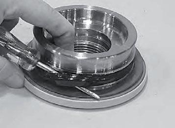
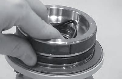
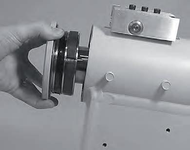
2. Coat the thrust washers (304) generously with lithium grease. Fit the thrust washer (304) on the shaft (2) and the cap (4).

3. Install the exclusion joint (304.1) in the appropriate housings in the shaft (2) and the cap (4) around the external edge of the thrust washer (304).
1. Before reassembly, gather all the parts and tools together in one place. Use the cutaway drawing as a reference for orienting the seals. 4. Fit the main pressure seal (205) on the shaft (2) and the cap (4) using a seal fi tting tool (see “Tools required” on page 6). Use the tool for seals with a circular movement.

Assembly
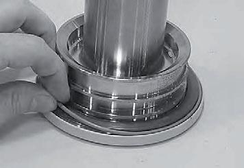
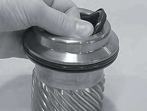
5. Fit the wear guide (302) on the cap (4) and the shaft (2).
6. Fit the O-ring (204) and the thrust ring (207) in the housing for the cap’s internal seal (4).
7. Fit the internal T seal (200) in the appropriate housing on the piston (3). Use a circular movement to ensure that the seal is correctly fi tted in the housing.
Fit the external T seal (202) stretching it around the housing with a circular movement.
Each T seal has 2 thrust rings (see the orientation on the assembly drawing on page 8). Starting with the internal seal (300), fi t one end of the thrust ring in the internal housing and then insert the rest with a circular movement. Check that the bevelled ends overlap correctly. Fit the other thrust ring in the upper housing. Repeat both these steps for the external seal (202).
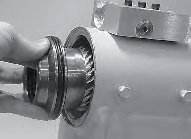
8. Insert the piston (3) in the casing (1), as shown, until the piston’s external seal (202) is in contact with the interior bore of the casing.


Assembly
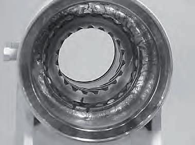
9. Looking down the casing’s bore from the end of the shaft fl ange, turn the piston (3) until the markings made on the piston and the casing (1) during dismantling are aligned as shown. With a rubber mallet insert the piston into the casing until the teeth in the grooves are in contact.
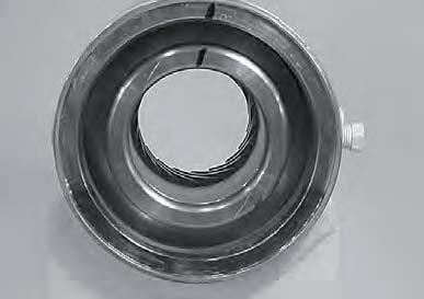
10. Looking down the bore from the opposite end of the casing (1), check that the sync markings are aligned correctly. Turn the piston as necessary until it is aligned and then gently insert the piston (3) in the casing until the grooves are engaged. Insert the piston into the casing until it comes in contact with the grooved crown. 11. Insert the shaft tube (2) in the piston (3).
Take care not to damage the piston’s seals.
Do not engage the teeth of the piston’s grooves at this time.
12. Looking at the actuator from the end opposite the shaft fl ange, use the existing sync markings to align the teeth of the shaft’s grooves (2) to the teeth of the piston’s internal grooves (3). When the markings are aligned, tap the end of the shaft fl ange gently with a rubber mallet until the teeth are engaged.
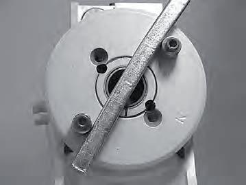
13. Fit 2 bolts in the fl ange’s threaded holes.
With a metal bar, turn the shaft in the clockwise direction until the wear guides rest of the inside bore of the casing.
Assembly
ADVICE When the shaft is turning, take care not to disengage the piston and casing grooves.
14. Fit the stop tube (400) on the end of the shaft if necessary. The stop tubes are available as an option to restrict the actuator’s rotation.

15. Coat the threads on the end of the shaft with anti-grip grease to avoid scuffi ng. 17. Tighten the cap (4) with a metal bar. In most cases, the initial holes for the locking pins will be aligned.

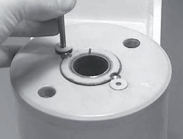
18. Insert the locking pins (109) supplied in the Helac seals kit with the depression facing upwards. Then push the locking pins right down to the bottom of the hole with a punch.
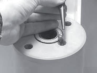
16. Screw the cap (4) on to the shaft (2). Check that the wear guide remains in place on the cap while it is being screwed into the casing (1). 19. Insert the locking screws (113) in the locking pins. Tighten to a torque of 2.8 Nm (25 in-lb).