2 minute read
Operating principle


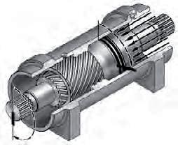
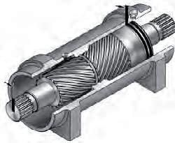
The L20 Series rotary actuator is a simple mechanism that uses Helac’s sliding channel technology to convert the piston’s linear motion into powerful shaft rotation. As shown in the illustration below left, each actuator consists of a casing with an integral grooved crown (1) and only two moving parts: the central shaft (2) and the ring piston sleeve (3). Please note that the L20 actuator’s shaft is fi tted with an integral mounting fl ange and a bearing, which are not shown in the illustration.
The teeth in the spiral grooves machined onto the shaft engage with the corresponding grooves on the piston’s internal diameter. The piston’s external diameter has a second set of grooves, with reverse pitch, which engage with the corresponding grooves in the casing’s crown.
As hydraulic pressure is applied, the piston moves proportionally in the axial direction in the casing, in similar fashion to the operation of a hydraulic cylinder, while simultaneously the grooves drive the shaft’s rotation. When the control valve is closed, the oil is sealed inside the casing, preventing the piston from moving and locking the shaft fi rmly in position. The shaft is supported radially by the large upper and the lower radial bearings (see the drawings on pages 8 and 9). In the axial direction, the shaft is separated from the casing by upper and lower end stop washers. The cap is adjusted for axial play and locked in position with locking screws or pins.
The L20 Series comes in various sizes. All the actuators in the L20 Series have the same nominal internal diameter and the same basic elements, although the overall confi guration of the parts may vary slightly depending on the model’s function.
Several L20 actuators are factory-fi tted with balancing valves with four main functions:
• To protect the actuator in the event of an overload • To enable the actuator to hold a given position without drifting when an external load is applied • To reduce hydraulic rebound by pressurising the hydraulic fl uid • To provide a controlled stable rotation rate under off -centred load conditions.
1
22 3
Bars indicate the starting positions for the piston and the shaft. Arrows indicate the direction in which they rotate. The casing, together with its integral grooved crown, remains stationary. For the purposes of clarity, the shaft clamp, the bearings and the caps are not marked. Application of fl uid under pressure moves the piston in an axial direction, while the spiral grooves simultaneously turn the piston and the shaft. The double-spiral design increases rotation: the shaft rotates at approximately twice the piston’s rate. Application of pressure to the opposite orifi ce returns the piston and the shaft to their initial positions.