
8 minute read
Transmission Torque Charts


General :
To work or dismantle the transmission form engine, first remove the bellow aggregate or assemblies.
1.Fender assembly
2.Hydraulic assembly
3.Electrical system.
4.Linkage, pipes & fittings
5.Three point Linkages
6.Seat assembly
7.Scuttle assembly
8.Steering assembly
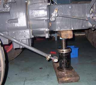
Jack the tractor with proper jack or hoist
Remove the transmission breather / dipstick for free flow of transmission oil.
Loosen the bolts of the tyre & remove both the tyres.
Loosen the drain the plug of the transmission & drain the transmission oil.
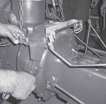
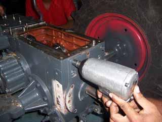
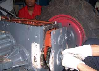
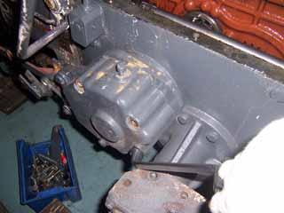
Removal of Clutch Housing & Connection
1.Remove the bolts mounting the clutch housing to engine.
2.Separate the engine form the clutch housing.
3.Remove the spring of clutch release sleeve & remove the clutch release sleeve with bearing.
4.Remove the Clutch housing hand hole cover by removing 6 nos of bolts mounting it on the clutch housing.
5.Remove the clutch release bearing shaft & fork as follows a.Remove 2 nos of bolt & spring washer of clutch release with the help of spanner. b.Remove the RH circlip of clutch release shaft c.Tap the clutch release shaft from the RH side with the help of mallet. d.Hold the fork with one hand & pull out the clutch release shaft by other hand. Note:- The clutch release shaft has a circlip on the LH also which acts as retainer & avoids fouling of actuating portion of the shaft with the housing.
9.Remove the coupling by removing the roll pins with the help of roll pin punch.
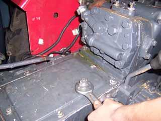
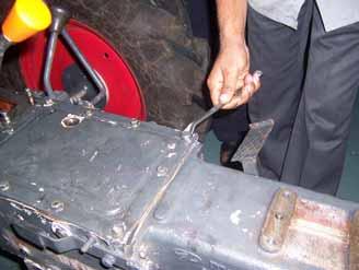
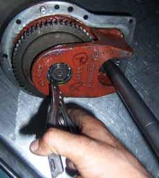
6.Remove the 8 nos of bolts mounting the clutch housing to the transmission case.
7.Remove the clutch housing in straight direction, if not the drive shaft may get bend.
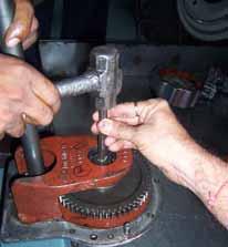
8.Remove the roll pins of transmission drive shaft with the help of roll pin punch & remove the drive shaft.
10.Clean all the parts with the help of cleaning fluid & inspect of wear & damage if found beyond permissible replace the same with new one.
Note: Always use new gaskets & roll pins at the time of assembly.
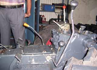
Dismantling of Rail Assembly
1.Remove the Hi Low Reverse shift lever by removing the double roll pin with help of roll pin punch & hammer.
2.Remove the cotter pin & plain washer of the link actuating the gear shift rail.
3.Remove the external circlip of gear shift lever with the help of circlip plier .
4.Remove the washer retaining the gear shift lever.
5.Then remove the gear shift lever with actuating link.
Note:- The rail has spring & ball on it at the forks.
14.Remove the forks form the transmission.
15.Clean all the parts with the help of cleaning fluid & inspect all the parts for wear & damage, replace if necessary.
Note: Use new seals, roll pins, cotter pins & gaskets at the time of assembly.
Dismantling of PTO Assembly
1.Remove 10 nos of bolts & spring lock washer of rear PTO cover with the help of a 8 mm spanner.
2.Slightly tap on the PTO cover on the edge with the help of mallet
6.Remove the
7.With the help of circlip piler remove the circlip of PTO drive shaft bearing.
8.Tap & remove the bearing of PTO shaft drive shaft.
9.Remove 3 nos of bolt & spring lock washer of PTO oil seal retainer with the help of 8 mm spanner.
10.Pull & remove the PTO oil seal retainer.
11.Remove the PTO oil seal.
12.Remove the front & rear circlip of main PTO shaft.
14.Tap
18.Remove the roll pin of PTO shift lever with the help of roll pin punch & draw out the PTO shift lever with ball & spring.
19.Remove the bolt & spring lock washer of PTO shifter shaft retaining plate with the help of 8 mm spanner & remove the PTO shifter retaining shaft.
20.Rotate & remove the PTO shifter by tapping with the mallet from the outside.
21.Remove the PTO shifter oil seal.
22.Clean all the parts with the help of cleaning fluid & inspect all the parts for wear & damage, replace if necessary.
Note: Always Use new seals & circlips at the time of assembly.
Dismantling of Brae Assembly
1.Remove 4 nos of hexagonal headed bolts & washer, mounting the brake assembly to the transmission with the 10 mm spanner.
3.Remove the breather.
4.Remove the cotter pin of the actuating disc pull rod & remove the bolt of the pull rod.
5.Remove the pin of the tension link by removing the cotter pin & washer with pin mounting the tension link on the brake housing.
6.Pull out the actuating assembly.
7.Remove the rubber boot mounting on the brake housing.
8.Remove the friction disc.
9.Dismantling of actuating disc assembly.
a.To remove the actuating disc assembly from the brake assembly remove the pin connecting the pull rod & crank link by removing the ‘R’ pin.
b.Remove the pull rod & actuating unit assembly from the housing.
c.To separate the two actuating disc, remove the 2 nos of springs holding the disc together with the help of screw driver or plier.
d.Remove the two discs & take out the 4 nos of Steel balls.
eRemove the crank link of each actuating disc by removing the nut & bolt.
10.Remove the inner friction disc.
11.Clean all the part with the help of cleaning fluid except the friction disc & inspect all for wear & damages. If found beyond limit replace the same with new one.
Dismantling of Reverse Idler Assembly
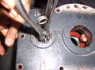
1.Remove the grub screw retaining the reverse idler assembly on the transmission case with the help of 10 mm spanner.
2.Tap & remove the reverse idler assembly with the help of mallet from the rear side of the transmission.
3.Remove the external circlip retaining the reverse idler gear in the reverse idler shaft with the help of external circlip plier.
4.Remove the thrust washer.
5.Remove the reverse idler gear from the shaft.
6.Remove the snap ring from the reverse idler gear & remove the 2 nos of needle roller bearing from it.
7.Clean all the part with the help of cleaning fluid & inspect them for wear & damage, replace if found worn & damage. Note: While assembly ensure that the reverse idler shaft half cut portion is on the top side & match the hole of the reverse idler shaft with the help of a round rod. (The half cut on the reverse idler shaft is provided for lubrication of the reverse idler assembly.)
2.Tap & remove the bull cage LH & RH with the help of mallet. Hold the differential cage assembly while removing the bull cage assembly LH & RH.
3.Remove the adaptor of bull cage LH & RH with the help of screw driver.
4.Remove the shims mounted on the bull cage.
Dismantling of Differential Assembly
5.Remove the Bull cum Bevel gear shaft from the cage with the help of mallet from both LH & RH.
6.Remove the circlip of bull cage bearing & remove the bearing.
7.Unlock the lock plate of the bull shaft & remove the nut with lock plate form the bull shaft.
8.Remove the integral stud, inserted in the bull shaft.
2.Unlock the lock plate of bull gear locking nut & remove the lock nut with the spanner.
9.Dismantling of differential cage assembly.
a.Unlock the lock plate of bull cage cross shaft & remove the 5 nos of bolts mounting the cross shaft to the crown wheel. The cross shaft will come out with the bevel pinion gear.
3.Remove the bull gear & conical spacer from the transmission.
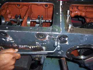
4.Remove the 7 nos of bolts & spring washer mounting the rear axle assembly to the transmission with the help of 10 mm spanner. Place the assembly in a clean place.
5.Tap the rear axle inner end with the help of mallet till it comes out from the inner bearing of the rear axle carrier.
b.Remove the bevel pinion gear & bevel pinion shaft
10.Clean all the part with the help of cleaning fluid & inspect all the parts for wear & damage. Replace if found, with new one.
Note: Always use new seals & circlips at the time of assembly.
Dismantling of Rear Axle Assembly
1.Jack the rear axle assembly with the help of hydraulic hoist & chain.
6.Further tap on the rear axle wheel mounting area in diagonal sequence with the help of mallet till the rear axle comes out.
7.Remove 4 nos of bolts & washer of rear axle retainer with the help of 8 mm spanner & remove the rear axle retainer.
8.Remove the oil seal form the retainer.
9.Remove the inner bearing by remove the retaining circlip with help of circlip plier, also remove the outer bearing.
10.Clean all the parts with the help of cleaning fluid & inspect all the parts for wear & damage, replace defective & worn out parts with new ones.
Note: Use new seals, lock nuts & circlips at the time of assembly.
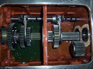
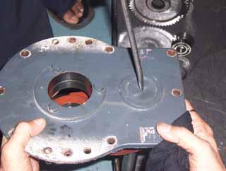
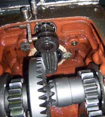
Dismantling of Counter Shaft Assembly (Driving Shaft Assembly)
1.Remove the 3 nos of bolts & washer of Counter shaft retainer with the help of 8 no. spanner.
6.Hold the 1st & 2nd driving gear with one hand & with other hand pull out the counter shaft out of the transmission case. Remove the 1st & 2nd driving cluster gear with shims & rear spacer from the transmission.
7.Remove the bearings from retainer, mid wall of transmission & rear wall of the transmission. To remove the retainer bearing & rear transmission bearing first remove the circlip form the transmission.
8.Clean all the part with the help of cleaning fluid & inspect all the part for wear & damage, replace with new one if found.
2.Remove the retainer with oil seal by tapping the retainer with mallet.
3.Remove the rear circlip on the counter shaft with the help of circlip plier.
4.Slightly tap the counter shaft from the rear end with the help of mallet.
5.Hold the Hi low Reverse cluster gear with one hand & with other pull out the counter shaft from front side till the Hi low reverse cluster gear is free to come out from the transmission case. Also, remove the spacer which is at the front & rear end of the cluster gear. The cluster gear has 3 nos of needle roller bearing & 2 nos of plastic bush inside it.
Note: Always use new Oil seals & circlips at the time of assembly
Dismantling of Spline Shaft Assembly (Driven Shaft Assembly)
5.Tap the spline shaft slightly with the help of mallet.
6.Hold the Hi low driven gear with one hand & with other pull out the pinion shaft which has double ball bearing, spacer & circlip. Also remove the Hi low driven gear & shims from the housing.
7.Hold the constant mesh gear with one hand & with other pull the spline shaft till the constant mesh gear is free to come out of the transmission case, remove the constant mesh gear with stepped spacer.
8.Remove the spacer mounted on the spline shaft & remove the 2nd & 3rd driven cluster gear.
9.Remove the spline shaft with mid bearing & circlip from transmission case.
10.Remove the circlip & remove the bearing of the spline shaft.
11.Remove the front bearing, oil seal from the retainer & double bearing from the spline shaft.
12.Clean all the part with the help of cleaning fluid & inspect all the part wear & damage replace with new one if found.
Note: Always use new oil seals & circlips at the time of assembly.
For all above assemblies the assembly will be done in the reverse way of dismantling, although below important adjustment are to be carried out at the time of assembly step by step.
HYDRA HYDRA HYDRA HYDRA HYDRA ULIC ULIC ULIC ULIC ULIC S S S S S
HYDRA HYDRA HYDRA HYDRA HYDRA ULIC ULIC ULIC ULIC ULIC S S S S S
HYDRA HYDRA HYDRA HYDRA HYDRA ULIC ULIC ULIC ULIC ULIC S S S S S
Hydraulic Specification & Torque Values
Torque Values
2Mounting Bolts18 to-20
4Quadrant Tightening Bolt20 to 25
5Quadrant Mounting Bolts35 to 40
6Control Valve Mounting Bolts95 to 101
7Draft Sensing Bolts96 to 102
8Hydraulic Mounting Bolts41 to 45
9Hydraulic Mounting Studs55 to 60
10Hydraulic Mounting Nut41 to 45
11DC Sensing Nut15
12DC Sensing Lock Nut25


