7 minute read
Engine Torque Values


TORQUE CHART FOR YUVRAJ 215 - FMW100 ENGINE
TORQUE-Nm NO.
SR.DESCRIPTION & BOLT/NUT/STUD USED
CRANKCASE SUB-ASSEMBLY
1Fip.Mtg Stud to crank case(M8 x 22)15 to 20 Nm
2Main brg housing mtg stud to crank case- ( M10 x 20)25 to 30 Nm
3Camfollwer bkt Allen bolt (M10 x 48.5 - 12.9)55 to 60Nm
4Stud for Cyhead at rocker side45 to 50 Nm
5Stud for Cyhead at injector side46 to 50 Nm
6Engine flange mtg bolt (M 12 x 30)65 to 70 Nm
7Oil sump mtg bolt (M8 x16 - 8.8)20 to 25 Nm
8Counter Unbalance shaft40 to 50 Nm
9Oil pump mtg bolt (Hex bolt - M8 x 35 – 8.8)25 to 30Nm
10Hex Bolt M8 X 20 For oil pump gear and water pump rear mounting bolts20 to 25Nm
11Oil Pump spacer Nylock nut25 to 30Nm
12Allen screw for Oil filter mtg bkt (M8 x 30 - 10.9)25 to 30Nm
13Hex bolt for low idle setting (M6 x 55 x 55 - 8.8)10 to 12Nm
13Hex bolt for Pull to stop lever bkt (M6 x 12-8.8)10 to 12 Nm
14Hex Socket Pipe Plug (M10X1)15 to 18 Nm
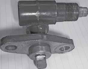
15Relief Valve Assembly25 to 30 Nm
CRANKSHAFT, FLYWHEEL SUB-ASSEMBLY
16Main brg housing Hex Nut ( M10 - 8)45 to 55 Nm
17Allen screw for flywheel (M12 x 75 - 12.9)100 to 120 Nm
18Allen screw for Balance weight (M10 x 50-10.9)65 to 70 Nm
TORQUE CHART FOR YUVRAJ 215 - FMW100 ENGINE
TORQUE-Nm NO.
SR.DESCRIPTION & BOLT/NUT/STUD USED
CAM SHAFT,PUSH ROD,TIMING COVER SUB-ASSEMBLY
19High Idle seting Hex Nut (M8 - 8)18 to 22 Nm
20Hex bolt for Timing cover (M 8 x 30 - 8.8)25 to 30Nm
21Hex bolt for P.T.O. shaft (M 10 x 45 - 8.8)48 to 52 Nm
PISTON,CON. ROD SUB -ASSEMBLY
22Con Rod bolt (M10 x 48 - 12.9)60 TO 65 Nm
23Stud for water inlet flange (M8 x 22 )12 to 15 Nm.
24Hex bolt for closed flang of water inlet (M8 x 12-8.8)20 to 25 Nm
CYLINDER HEAD SUB-ASSEMBLY
25Injector flange stud (M 8 x 40 - 5.6)10 to 12 Nm
26Exh. And Air Intake manifold mtg. stud (M10X42X1.5)45 to 50 Nm
27Exh.manifold mtg bolt (M 8 x 25)20 to 25 Nm
28Breather pipe mtg stud (M 6 x 30 - 5.8)10 to 12 Nm
29Hex nut for Adjustment screw of rocker (M8)18 to 22Nm
30Hex bolt for Rocker shaft locking (M6 x 16-8.8010 to 12 Nm
31Hex Nut for cy.head (M12)127 to 147 Nm
32Rocker cover hex bolt (M8 x 50-8.8)25 to 30 Nm
33Rocker cover hex bolt (M8 x 75-8.8)25 to 30 Nm
34Hex nut for breather pipe (M 6 – 8.8)10 to 12 Nm
35Water Temperature Sensor25 to30 Nm
36Oil Pressure Switch15 to 20 Nm
TORQUE CHART FOR YUVRAJ 215 - FMW100 ENGINE
SR.DESCRIPTION & BOLT/NUT/STUD USED TORQUE-Nm NO.
INJECTION EQUIPMENT SUB- ASSEMBLY
37Hex Nut for FIP (M8 - 8)18 to 22 Nm
38Hex bolt for H.P.pipe clamp mtg (M8x16-8.8)25 to 30 Nm
39Injector flange Hex Nut (M8 - 8)25 to 30 Nm
40Fuel filter bkt Mrg bolt (M10 x 30 - 8.8)45 to 50Nm
41Hex Nut for fuel filter mtg bolt (M10 - 8)45 to 50 Nm
42Fuel filter mtg bolt (M10 x 30 - 8.8)45 to 50 Nm
43Banjo Bolt M14 for fuel filter20 to 25 Nm
44M6 Banjo bolt for injector overflow pipe5 to 7 Nm
AIR FILTER, EXHAUST SILENCER SUB-ASSEMBLY to to 50 Nm
STARTER MOTOR, ALTERNATOR SUB-ASSEMBLY
TORQUE CHART FOR YUVRAJ 215 - FMW100 ENGINE
TORQUE-Nm NO.
SR.DESCRIPTION & BOLT/NUT/STUD USED
COOLING SYSTEM SUB-ASSEMBLY
55Hex bolt for water pumpmtg. Bkt.(Rear) (M8X20X8.8)25 to 30 Nm
56Hex bolt for water pulley and spacer (IM6X35X-8.8)10 to 12 Nm
57Hex bolt for Cooling fan and Spacer (M8 x 20-8.8)25 to 30 Nm
58Hex nut for Flange for Inlet Hose (M8 - 8)12 to 15 Nm.
59Hex bolt for Fan spacer (M6X30)10 to 12 Nm
60Hex bolt for Flange for Outlet Hose (M8 x 20-8.8)12 to 15 Nm.
ACCESSORIES SUB-ASSEMBLY
62Hyd pump mtg bkt Flange Headed Bolt(M12 x 75 - 12.9)45 to 50 Nm
63Hex bolt for hour meter adapter (M6X16X8.8)10 to 12 Nm
64Hex bolt for hour meter (M8 x 16 - 8.8)25 to 30 Nm
65Plug Magnetic Drain ( Oil Pan Drain Plug )40 to 50 Nm
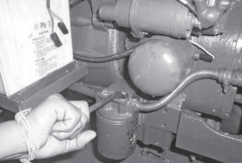
66Oil Filter15 to 20 Nm
67Fuel Injection Pump M12 Banjo bolt20 to 25 N.m
68Fuel Injection Pump M8 banjo bolt and fuel return line M8 banjo bolt6 to 10 N.m
69Tappet Bolt for Crankshaft Pulley45 to 50 Nm
70HPP Nut M12 at FIP and M14 at Injector End20 to 25 N.m
Engine
Removal
of Engine : Dismantling of Bonnet & Radiator –
1Remove the two nos. nuts of bonnet of LH & RH side.
5Remove the clip of radiator each inlet & outlet hose.
2Remove the two nos bolts of bonnet. & remove the Bonnet.
3Drain the coolant in the radiator by removing the radiator drain plug.
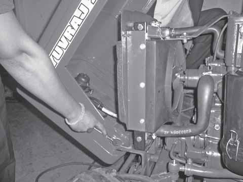
4Remove the brace plate of radiator
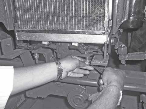
6Remove the two nos. radiator mounting spring loaded bolts & plain washer and remove the radiator.
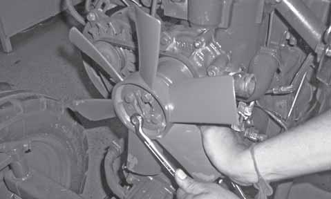
7Remove the four nos bolts (spanner size 12 mm) of fan blade & remove the fan blade.
Engine
17Remove
Engine
18Disconnect
19Remove
20Remove
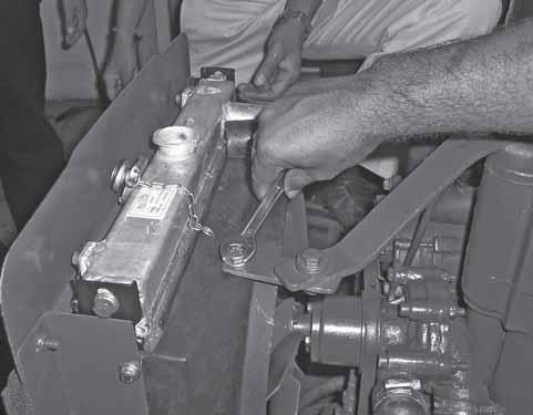
22Remove the accelerator linkage.
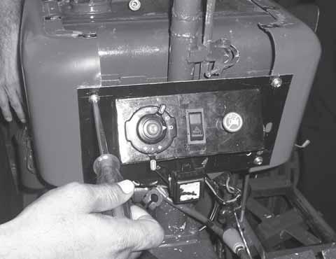
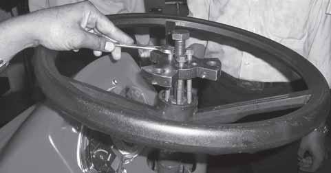
23Remove the three nos of bolts of steering mounting bracket (14mm- size) & remove the bracket.
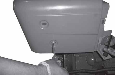
24Remove the two bolts of fuel tank mounting bracket. (19mm Size)& remove the bracket.
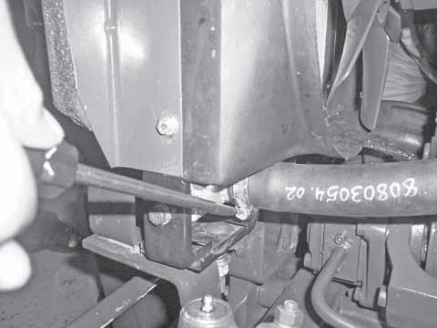
27Remove the radiator mounting bracket by removing the two nos bolts. (16mm).
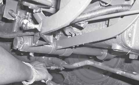
28Remove the four bolts (M12) of front axle support. & remove the support.
25Remove the nut connecting the drop arm to drag Link.
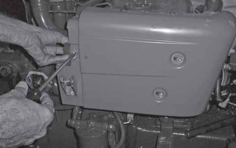
26Remove the two bolts of fuel filter & remove the fuel filter to pump pipe. Remove the filter.
29FAS will come along with the Front Axle.
30Remove the two bolts of fuel filter bracket & remove the bracket.
31Remove the two nut of inlet manifold (Spanner size :17mm) & remove the manifold & gasket.
34Remove the alternator by removing the bolt.
32Remove the two Nut of exhaust manifold (Spanner size 17mm) & remove the exhaust manifold.
35Remove the two bolts of alternator bracket & remove the bracket.(Spanner size 8mm)
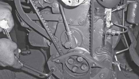
33Remove the three bolts of (Spanner size 12mm) alternator brace & remove the brace.
36Remove the two bolts of breather assembly (Spanner size 10mm) and separate it.
Engine
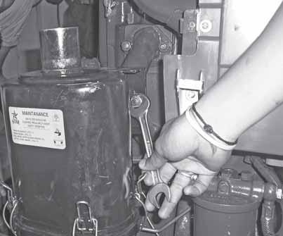
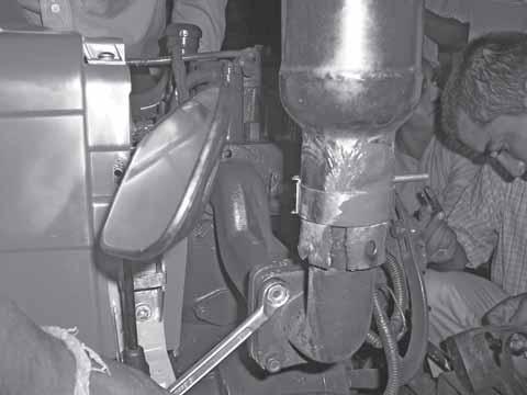
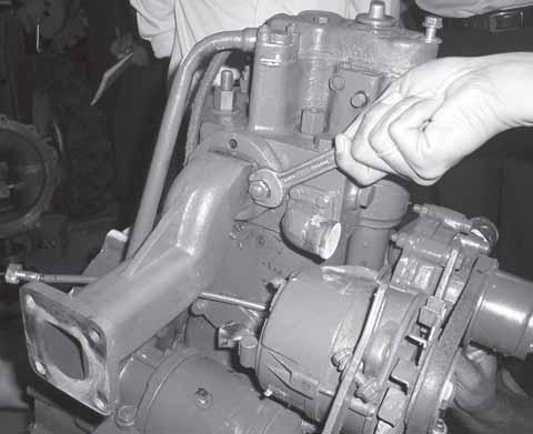
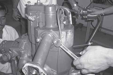
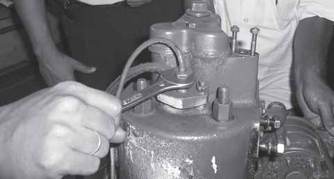
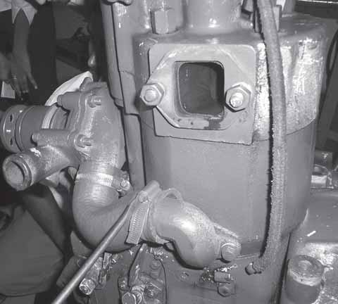
37Remove the nut connected to the injector & other nut on the crankcase (17mm), to remove the Fuel Pressure pipe loosen the clamp bolt.
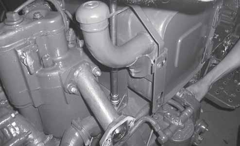
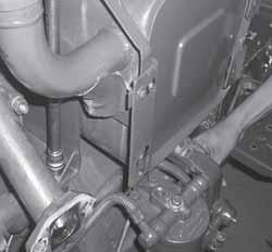
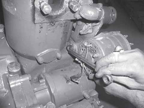
39Remove the two bolts of water pump & remove it. (Spanner size 13mm)
38Remove the two clips of the hose between the water pump and crankcase block.
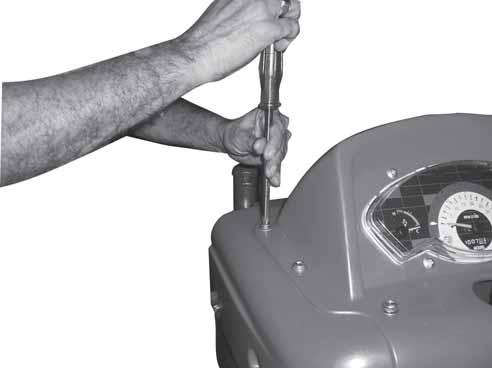
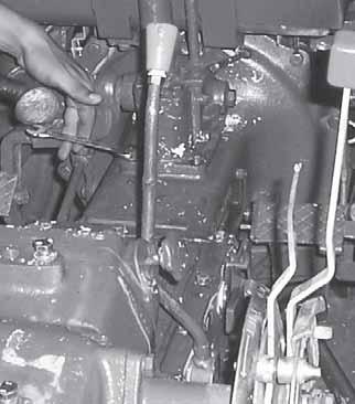
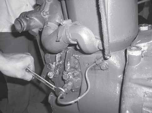
40Remove the hour meter adaptor by removing two bolts.
41Remove the three bolts of hour meter adaptor plate.
Engine
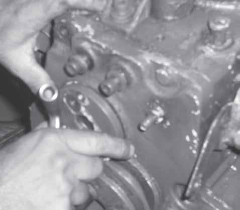
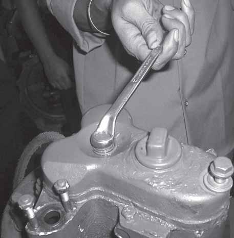
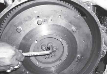
42Remove the crankshaft pulley by removing one bolt.( 16mm).
Dismantling procedure of the valve housing cover & cylinder head
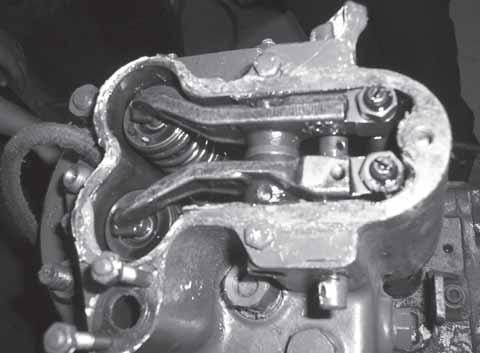
43Remove the two bolts of the valve housing cover & remove it.
45Remove the two nos bolts of rocker arm & remove the rocker arm shaft. (Rail of rocker arm).
46Remove the rocker arm & Push rods..
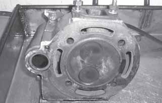
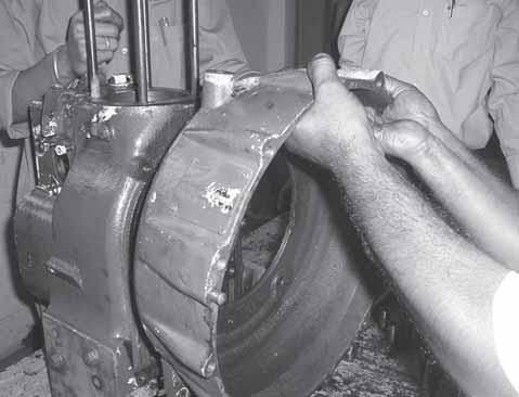
47Remove the cylinder head from the crankcase block.
Engine
48Valve Springs can be removed from the Cylinder head by removing the lock. Remove the top retainer, Spring, Bottom retainer and thrust washer.
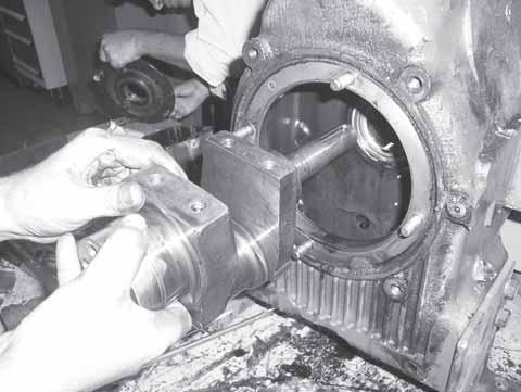
49Remove the cylinder head block by removing the dowel by pulling it.
Dismantling procedure of crankcase front cover-
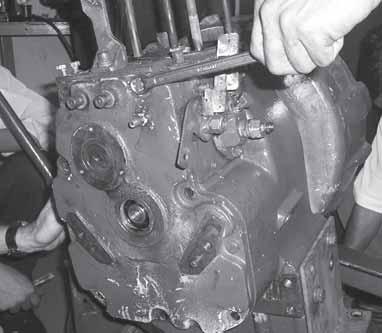
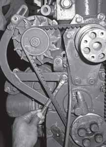
52Remove the nine bolts of the front engine cover.
Dismantling procedure of the Piston assembly.
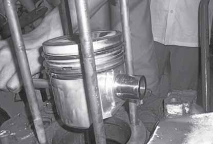
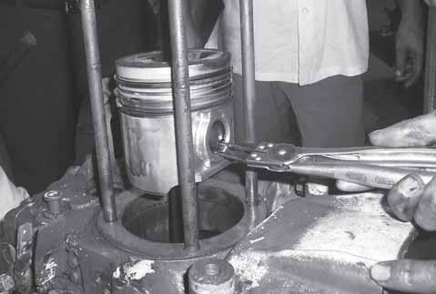
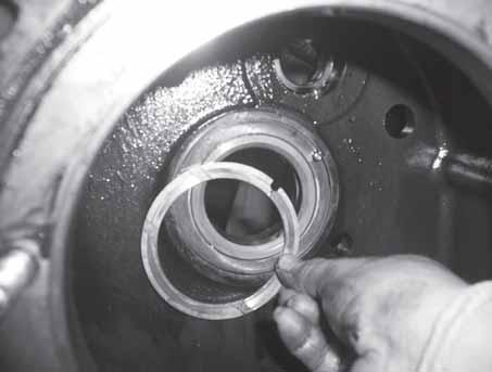
50Remove the circlip of piston pin.
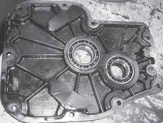
53Remove the engine front cover
54Remove the gasket front cover.
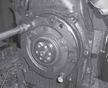
55Remove the spin on oil filter.
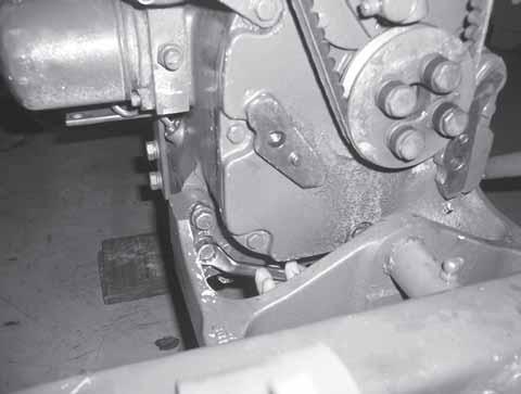
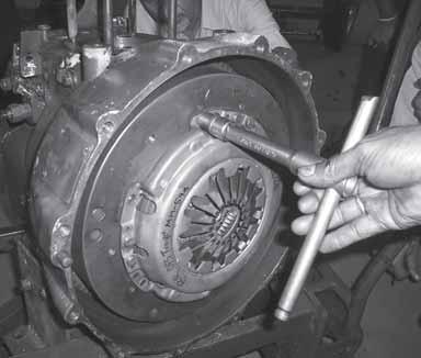
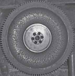
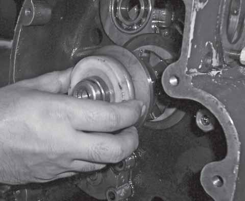
56Remove the six bolts of the clutch cover assembly (13mm).
57Remove the clutch.
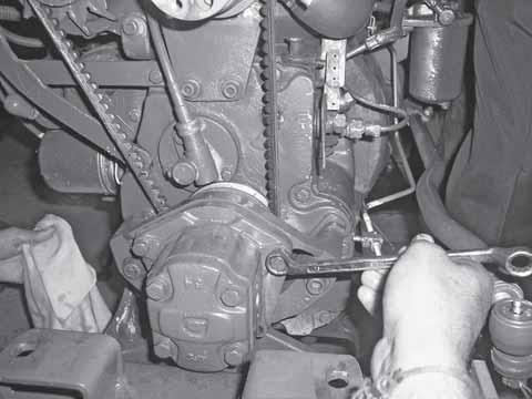
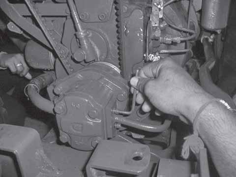
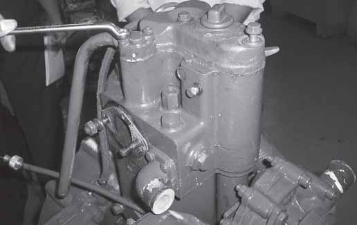
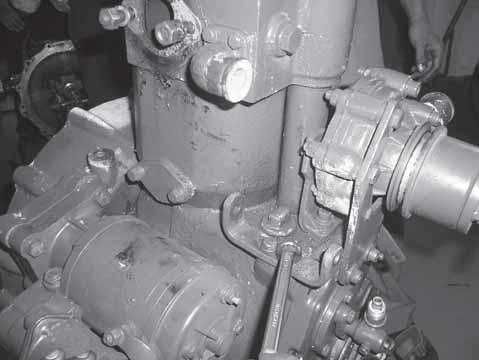
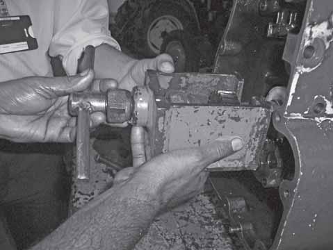
61Remove the three bolts to remove the fuel injection pump (13mm).
58Drain the oil from the oil pan.
59 Remove the nuts of the accelerator lever bracket.
62Remove the fuel injection pump & its gasket.
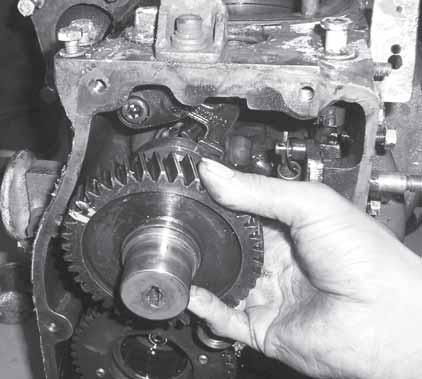
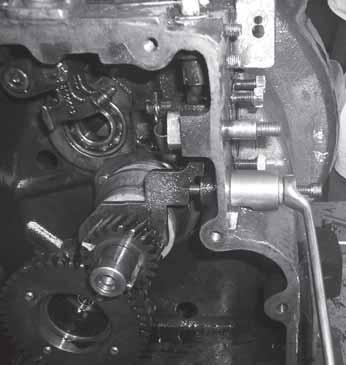
63Remove the camshaft.
Engine
Dismantling procedure of
the
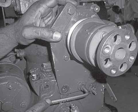
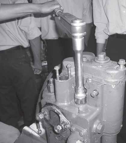
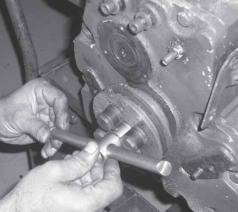
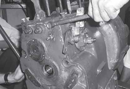
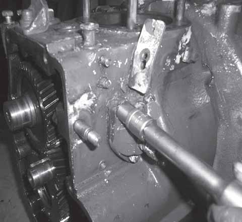
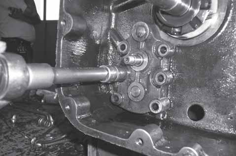
66Remove the inside circlip of the governor control shaft with the help of the circlip plier.
67Remove the governor control spindle by placing the puller (MST-H1-EN- )on the Crankcase. Screw the bolt such that the threaded portion fits into the spindle. Tighten the lock nut such that the spindle is pulled out along with the bolt.
68Remove the pin of the hand accelerator lever.
69Remove the spring connecting the governor control lever with hand accelerator lever.
73Remove
Engine
75Remove
•The Oil Pump gears are non-serviceable.
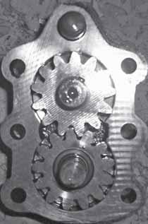
•Oil Pump has to be replaced in case of replacement required for gears
76Remove the 12 nos bolts of the oil pan
77Remove the oil pan.
78Remove the two bolts of the connecting rod cap & remove the connecting rod cap.
79Remove the two allen bolts of crank balance weight.
80Remove the crank balance weight.(2 nos)
81Remove the cam follower bracket & cam follower by removing Allen bolts. (8mm)
82Remove the relief valve assembly by loosening the nuts.
Engine
Before Assembly ensure that
1Use new gaskets, ‘o’ rings, Oil Seals and fasteners.
2All bearings must be cleaned & lubricated.
3All moving parts must be smeared with lubricants.
4Smear oil on oil seal lip before fitment.
5Use recommended Special Service tools.
Assembly :
Assembly is reverse of dismantling sequence. Some of the important adjustments that needs to be done are as follows :
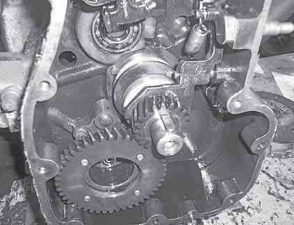
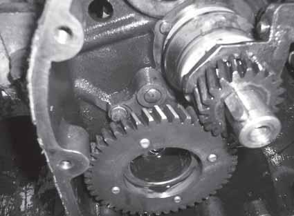
The Crankshaft –gear has one dot on it which should be matched with matching marks (two dots) on the camshaft gear.
On the Crankshaft front end another gear is mounted with the help of key way . This gear is called as PTO gear which is having one dot. This has to be matched with the two dots on the balancing gear. This Gear pair is provided to reduce engine vibrations.
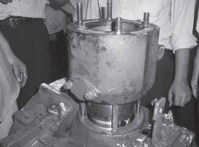
Bumping Clearance Setting ( Selection of Shims below the Cylinder block):
1Mount the Cylinder block on the crankcase without shims.
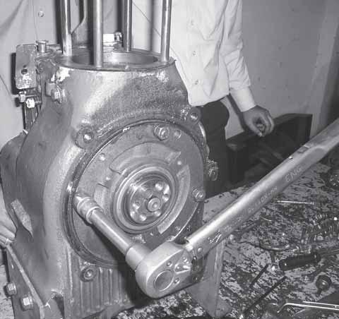
2Rotate the Crankpulley and get the piston in T.D.C position.
3Place the bumping clearance tool (MSTH1-EN- ) on the liner top face without cylinder head gasket. The tool can be placed on any of the two cylinder head studs and with the help of given spacers tighten the tool. Torquen the nuts to 40 Nm. This will ensure that the tapered portion of the Cylinder blocks sits properly in the crankcase.
4Rotate Crankpulley in clockwise/ anticlockwise and note the maximum dial reading at TDC. This is to ensure that piston is at the top dead centre position. If the reading is ‘X’mm then the shims required will be “ (X – 0.2 or 0.30) mm”.
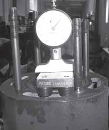
The shims are available in ‘3’ different sizes : 0.4 mm, 0.3 mm and 0.2mm. The
Engine
Value of X will always be greater then 0.30mm.
FIP Mounting Setting : There is a value in mm which is punched on the crankcase next to the FIP.
1Whenever the FIP is removed the no of shims to be replaced should be equal to the value on the Crankcase.
2If FIP is to be replaced, then value on the old FIP Should be noted.
3Value provided on new FIP to be noted. Now the revised number of shims = Value on Crankcase – Value on old FIP x 0.1 + Value on New FIP x 0.1


