5 minute read
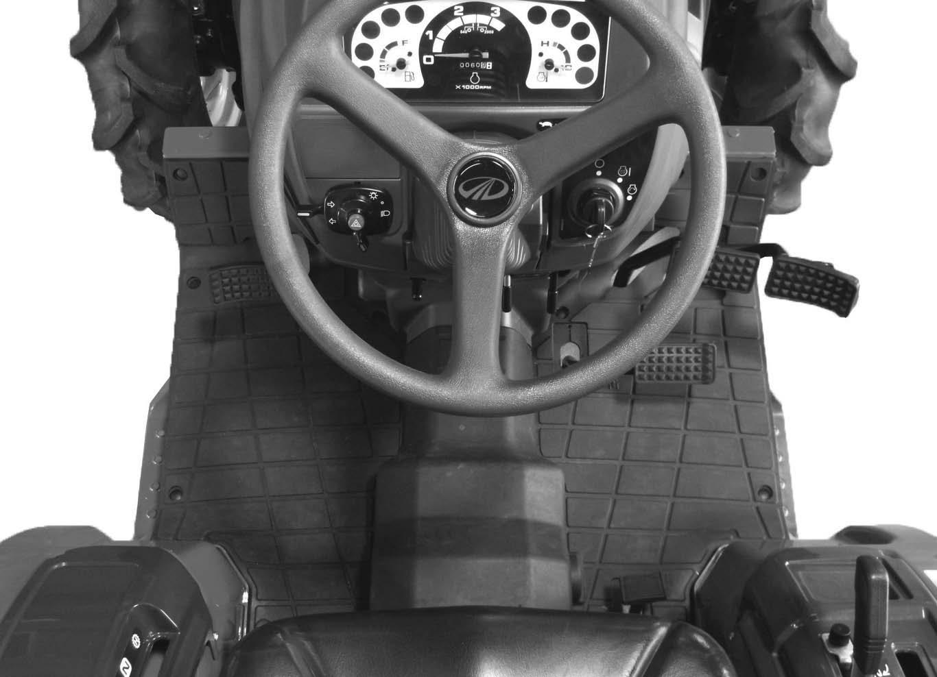
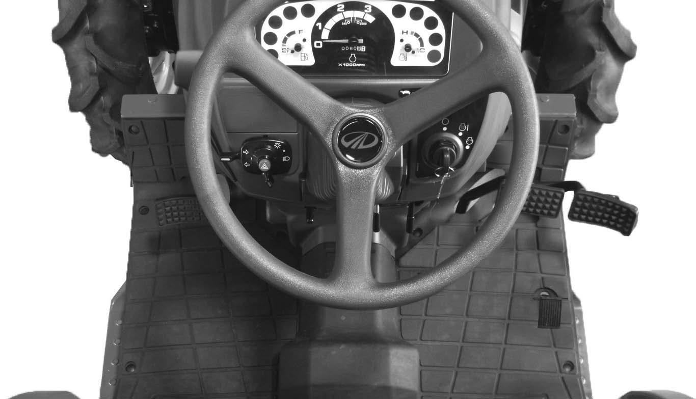
OPERATING CONTROLS


1. STARTER KEY SWITCH
The starter key switch can be removed in the OFF position. Three switch positions are as follows:
Position (OFF)
Engine and all lamps except the turn signal and flasher lamps are turned off.
Position (HEAT) & (ON)
First position clockwise from OFF. In this position (Engine not running) energizes the glow plugs. The charge indicator, glow plug indicator and oil pressure indicator will illuminate. The fuel gauge and temperature gauge will show correct values.
Position (START)
Turn the key fully clockwise against the force of the spring in the switch. The starter motor will turn the engine. Release the key immediately when the engine starts.
NOTE: To prevent operation by persons not authorized and the possible discharge of the battery, remove the starter key when you leave the tractor.
IMPORTANT: Do not keep the starter key switch in the ON position for a long time when the tractor is not operating.
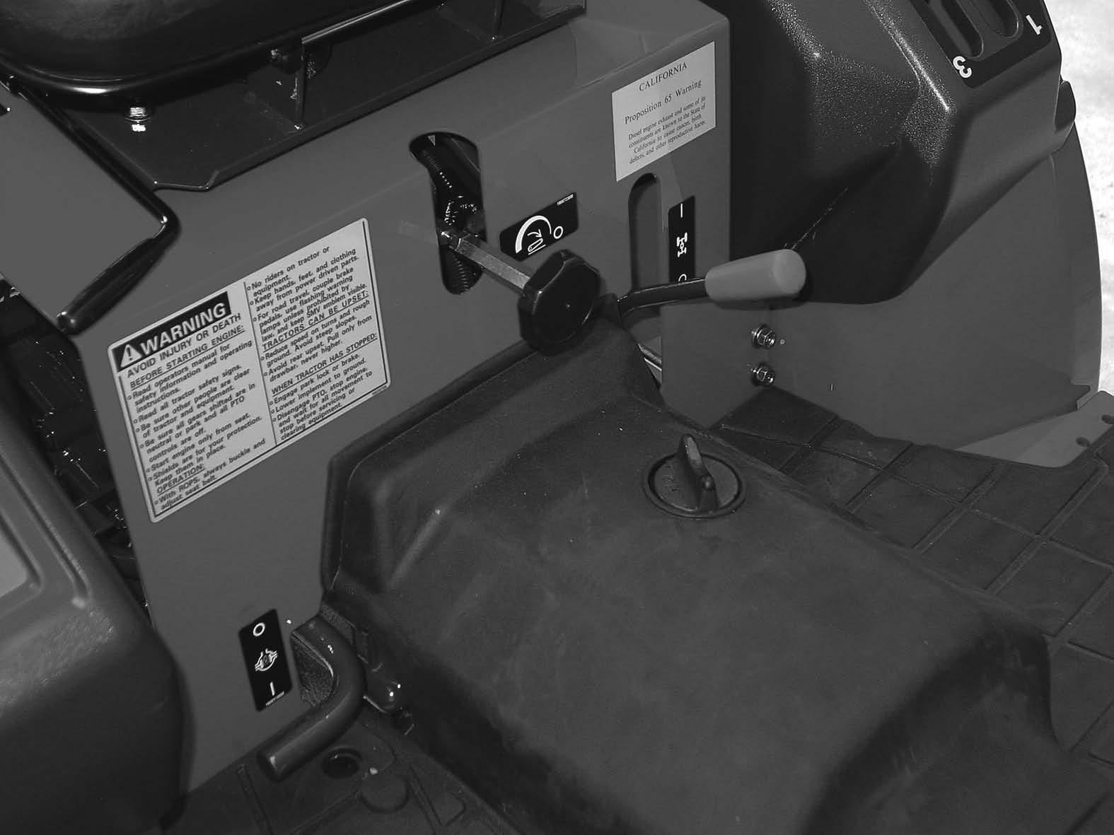
2. ENGINE SPEED CONTROL LEVER
ENGINE SPEED CONTROL LEVER
DECREASE
Pull the engine speed control lever to the rearward to increase the engine speed. Push the engine speed control lever forward to decrease the engine speed.
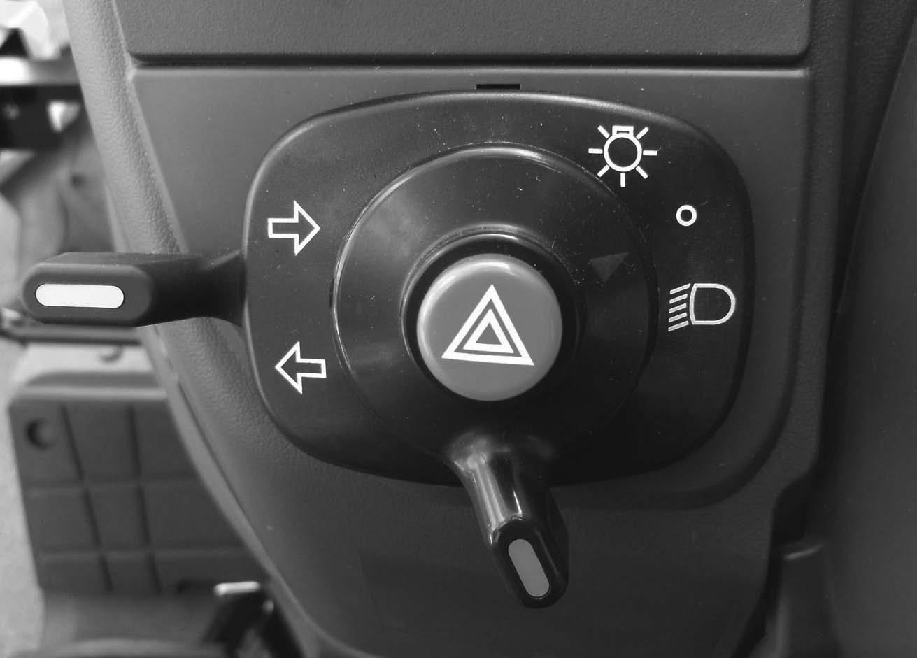
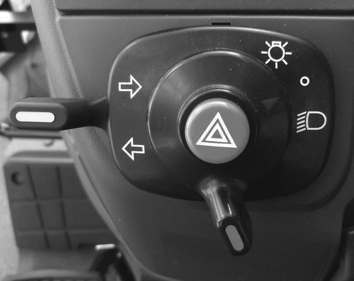
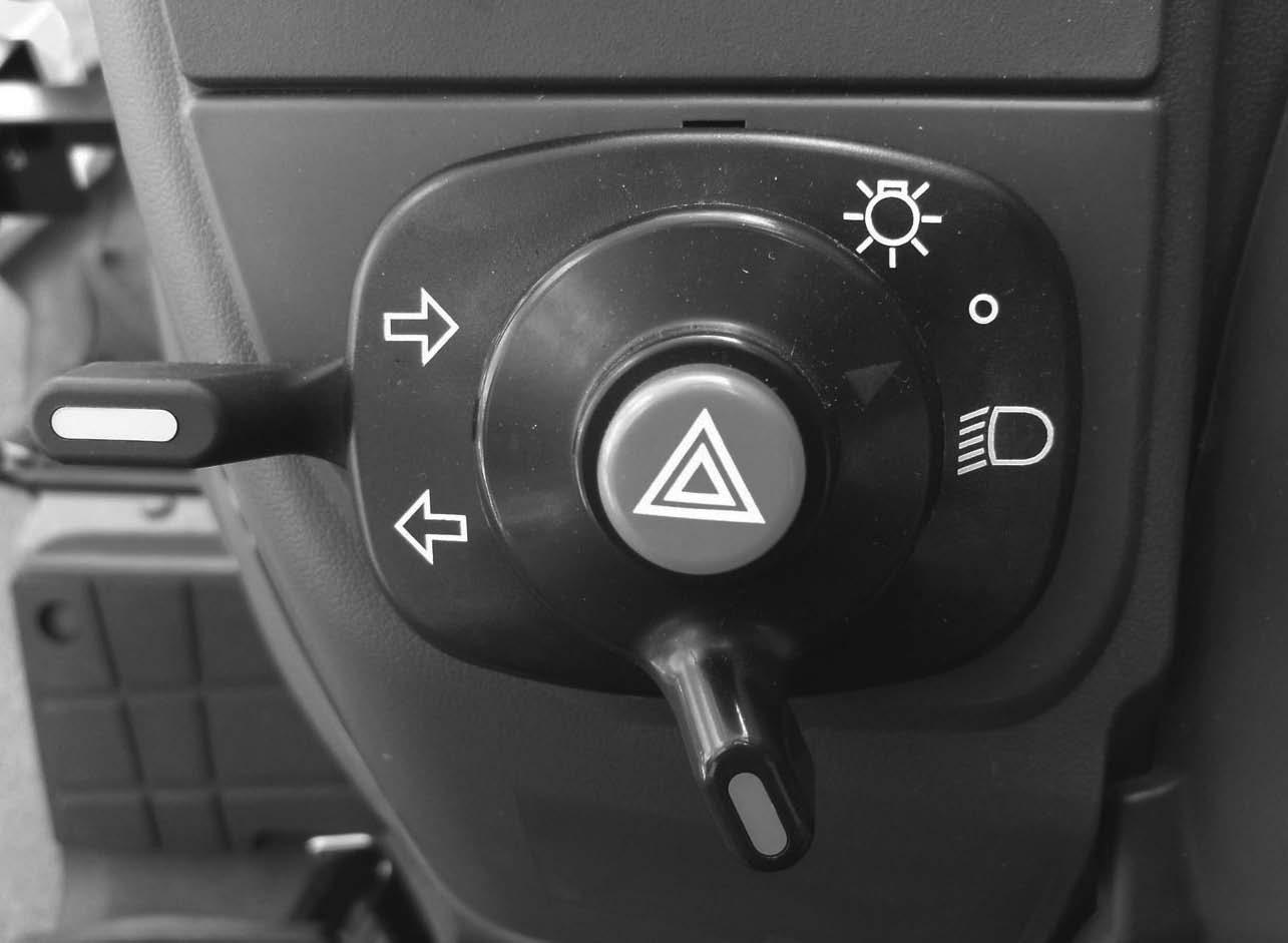
3. LAMP SWITCH Two position switch as follows:
ALL lamps are OFF. (Turn signal and flasher lamps can be turned on.)
First position clockwise illuminates head lamps, instrument panel and rear red lamp.
LAMP SWITCH
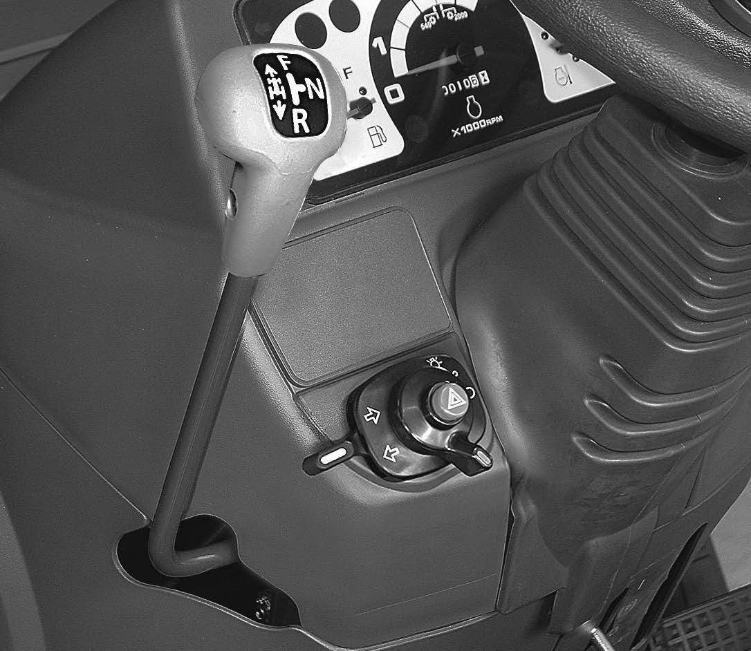
4. HAZARD SWITCH
HAZARD SWITCH
To flash the Flasher Lamps whenever the tractor is operated or traveling on roads.
5. TURN SIGNAL SWITCH
To indicate that you are going to turn the tractor to the RIGHT, move the turn signal switch to right . To indicate that you are going to turn the tractor to the LEFT, move the turn signal switch to left . Center position is OFF.
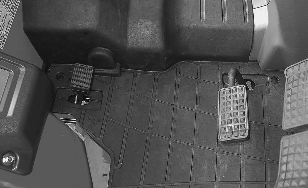
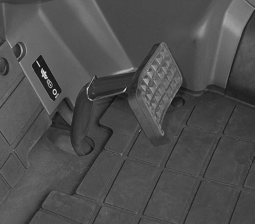
Control Levers and Pedals (Gear Drive)
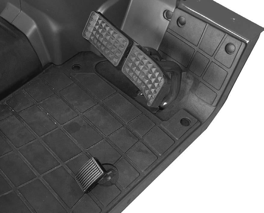
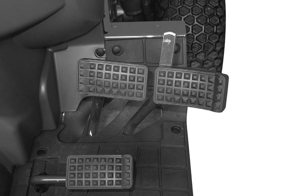
1.ACCELERATOR
Use this pedal when operating the tractor on the road. Push the pedal down to increase engine speed.
NOTE: The engine speed control lever must be set to give the slowest engine speed when the throttle pedal is used.
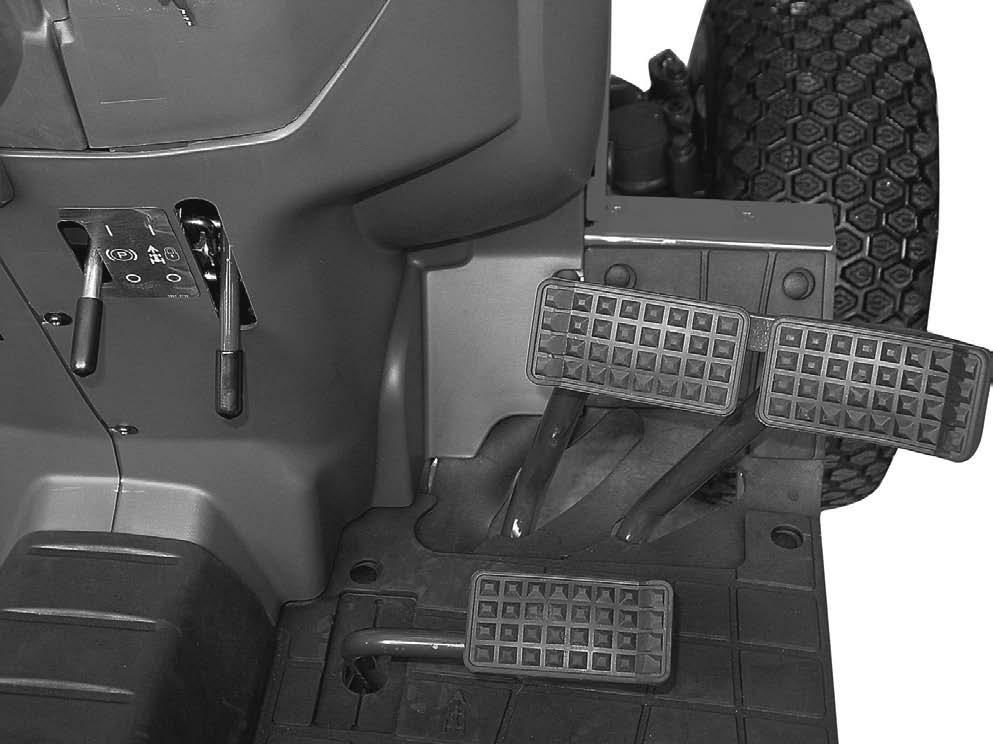
The control pedal is centralized to the neutral position by spring load. Push down on the front pedal to increase forward speed. Push down on the rear pedal to increase reverse speed.
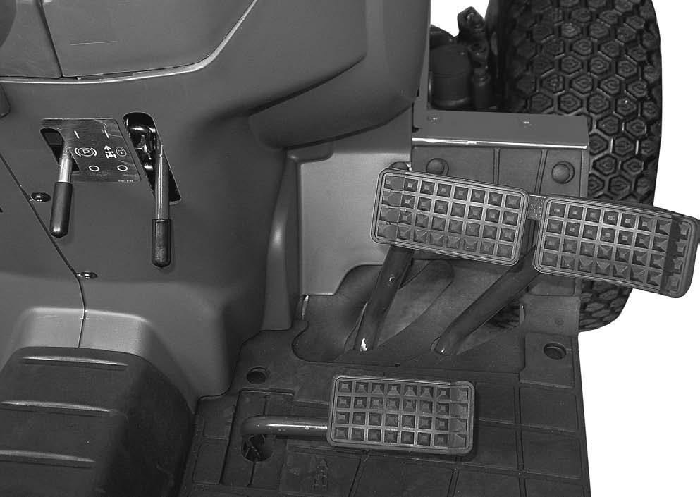
The pedals when locked together, provides braking to both rear wheels for stopping the tractor. When the brake pedals are unlocked, the pedals are used for individual braking of the rear wheels to aid in turning the tractor in soft soil conditions. Push the RH brake pedal down to slow or stop the RH rear tractor wheel, push the LH brake pedal down to slow or stop the LH rear wheel. The tractor will turn in the direction of the wheel that is slowed or stopped
The brake pedal lock is located at the brake pedal arms and is used to lock the two brake pedals together so that both brakes are applied.
CAUTION: Brake pedals must be locked together for road travel. This will insure uniform brake application and maximum stopping ability.
WARNING: Extra weight and bad traction conditions such as mud or ice increase your stopping distance. Remember that liquid in the tires, weight on the machine or wheels, tank filled with fertilizer, herbicides or insecticides – all these add weight and increase the distance you need in which to stop.
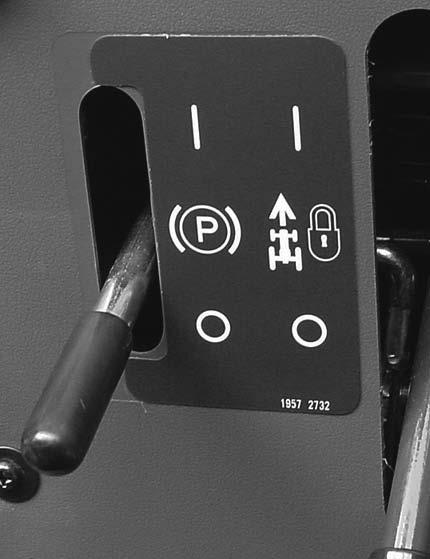
1. The park brake must be on to prevent movement of the tractor during stationary power takeoff work or when the tractor is parked. To engage the park brake, lock the brake pedals together, push down on the brake pedals and move the park brake lever upward. Push the brake pedal down to release the park brake.
2. Before getting off the tractor, disengage the PTO, lower all implements to the ground, place all control levers in their neutral positions, set the parking brake, stop the engine and remove the key.
3. If it is necessary to park on an incline, be sure to check the wheels to prevent accidental rolling of the machine.
(Hydrostatic Drive)
It is free on engine brake with the range lever engaged, be sure set the parking brake.
To keep a constant forward travel speed, move the lever fully upward, while holding the speed ratio control pedal at the desired speed. It does not work in reverse.
The clutch must be disengaged when starting the engine, stopping the tractor, storing the tractor and operating the following levers, gear shift lever, range shift lever rear PTO lever, MID PTO lever, MFD lever, shuttle shift lever.
For long term storage, lock the clutch pedal in the disengaged position. This will prevent the clutch disc from sticking to the engine flywheel.
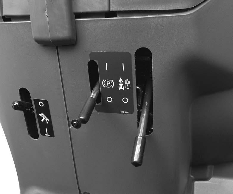
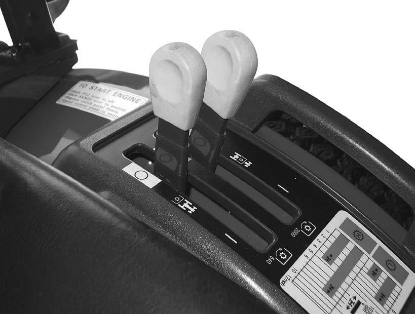
Control Levers (Gear Drive)
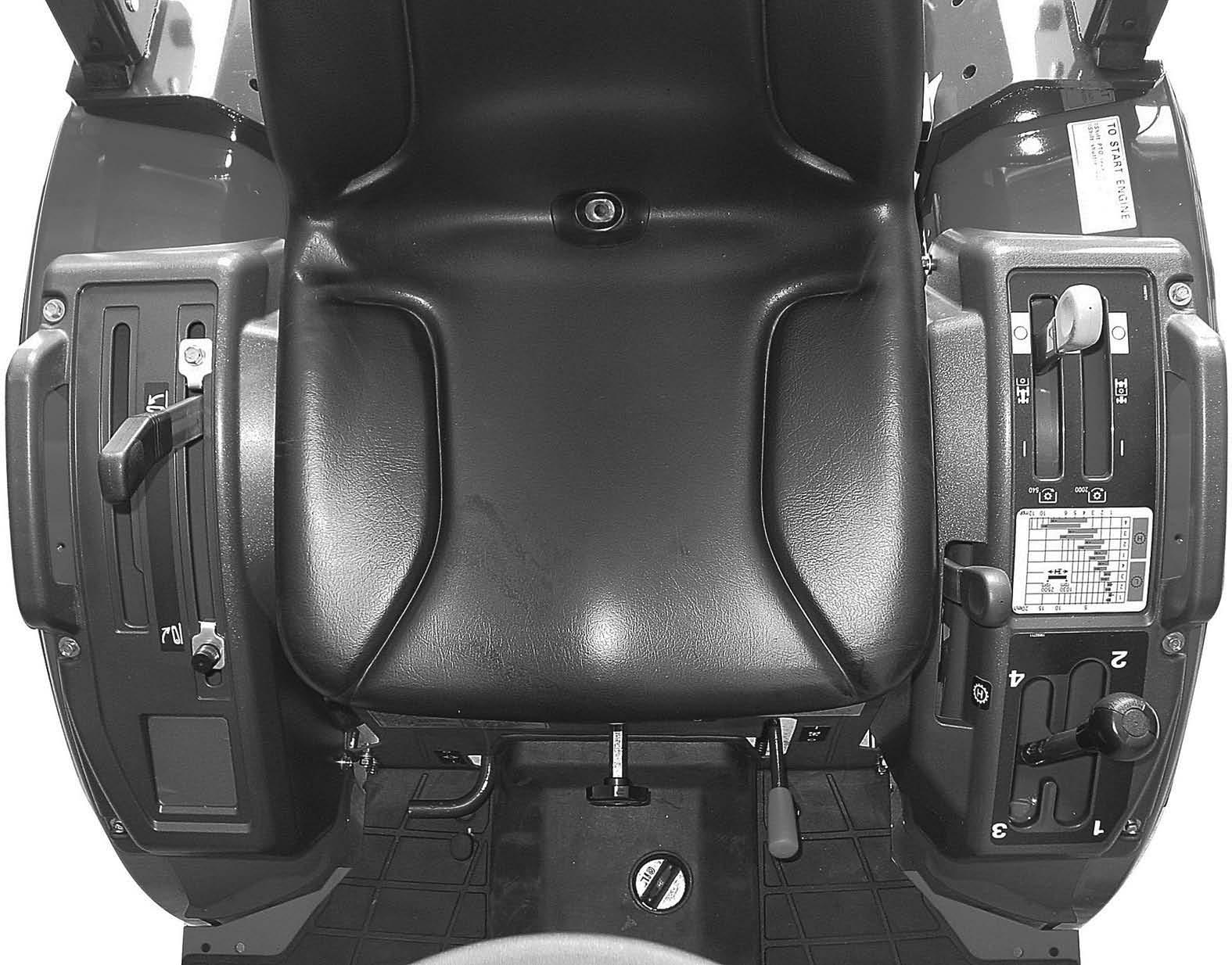
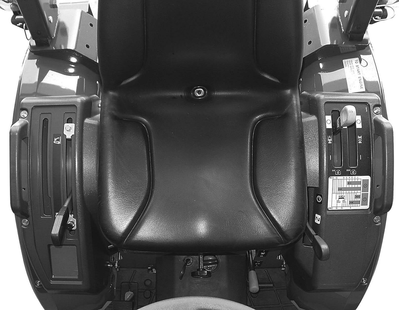
Move the range shift lever forward to place the transmission in H range. Move the lever rearward to place the transmission in L range.
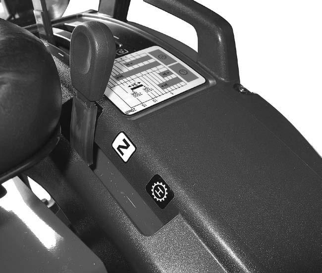
Move the range shift lever forward to place the transmission in H range. Move the lever to the rearward to place the transmission in L range. The center position between L and H places the transmission in N.
The shuttle shift lever is used to shift the transmission gear into forward of reverse position. Move the shuttle shift lever forward (F position) to the forward position. Move the shuttle shift lever rearward (R position) to the reverse position. The center position between F and R places the transmission in N position. (Neutral)
NOTE: Be sure the shuttle shift lever is in N (Engine start) position when starting the engine.
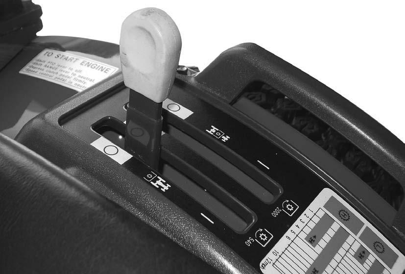
Move the lever forward to engage the REAR PTO. Move the lever rearward to disengage the Rear PTO.
NOTE: Be sure the Rear PTO control lever is in OFF position when starting the engine.
5. MID PTO CONTROL LEVER (If Equipped)
Move the lever forward to engage the Mid PTO. Move the lever rearward to disengage the Mid PTO.
NOTE: Be sure the Mid PTO control lever is in OFF position when starting the engine.
NOTE:
1. The Rear and Mid PTO shaft can be operated at the same time.
2. When not using the Mid PTO shaft, cover the shaft with the Mid PTO cover.
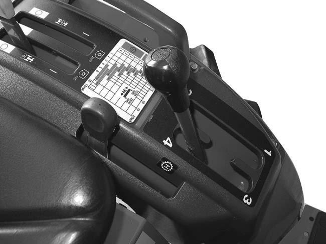
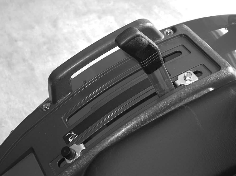
(Gear Drive)
Drive)
Use this lever to control the position of the hitch. Move the lever forward to lower the Three point hitch. Move the lever to the rearward to raise the Three point hitch.
(Gear Drive)
1.DIFFERENTIAL LOCK PEDAL
Push the pedal down to engage the differential lock. A spring inside of the differential lock pushes it out of engagement when pedal is released.
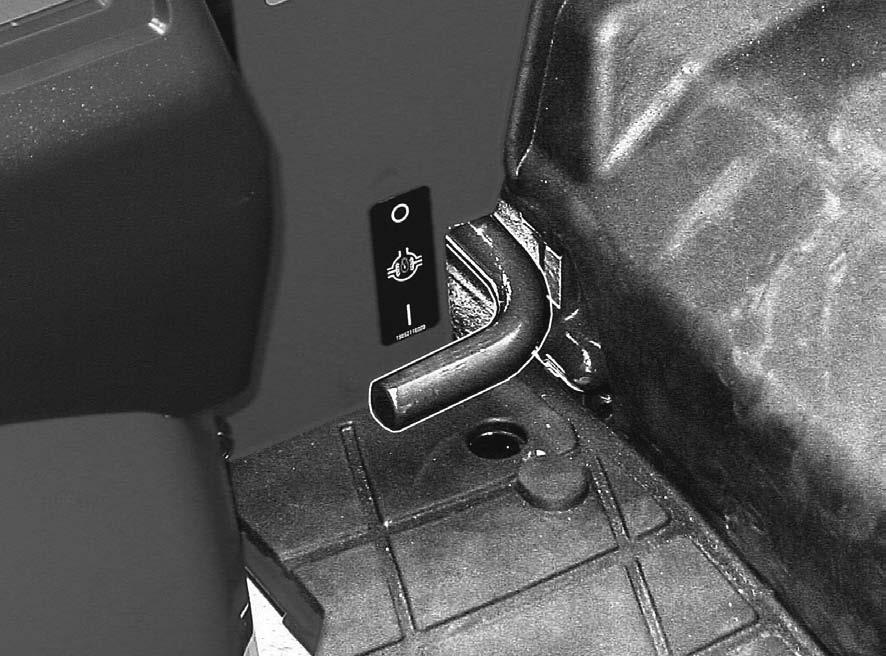
NOTE: When engaging the differential lock, push the clutch pedal down or bring speed ratio control pedal to Neutral, to stop the wheels that are rotating, then push the differential lock pedal. Do not operate the differential lock pedal while the wheels are rotating.
Do not drive on roads, or at high speed anywhere, with the differential lock engaged. Difficult steering will occur, and can result in an accident. In field operation, use the differential lock for traction improvement, but release for turning at row ends.
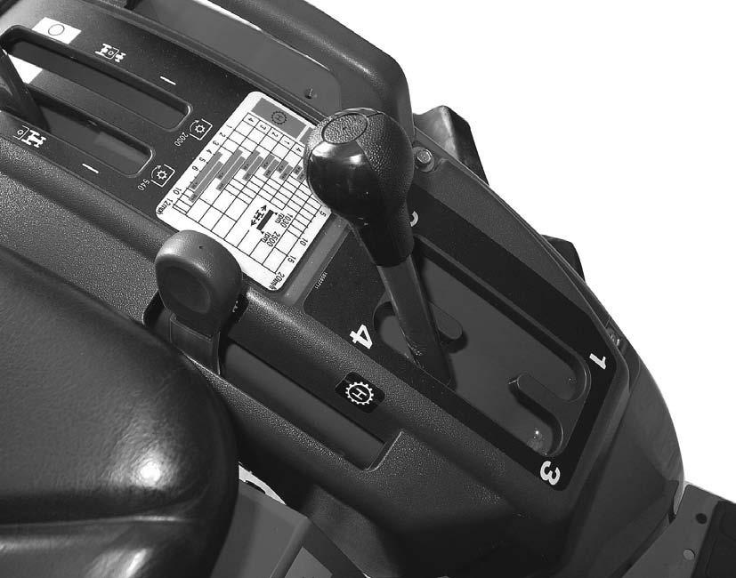
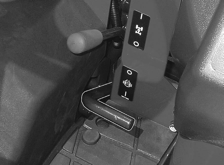
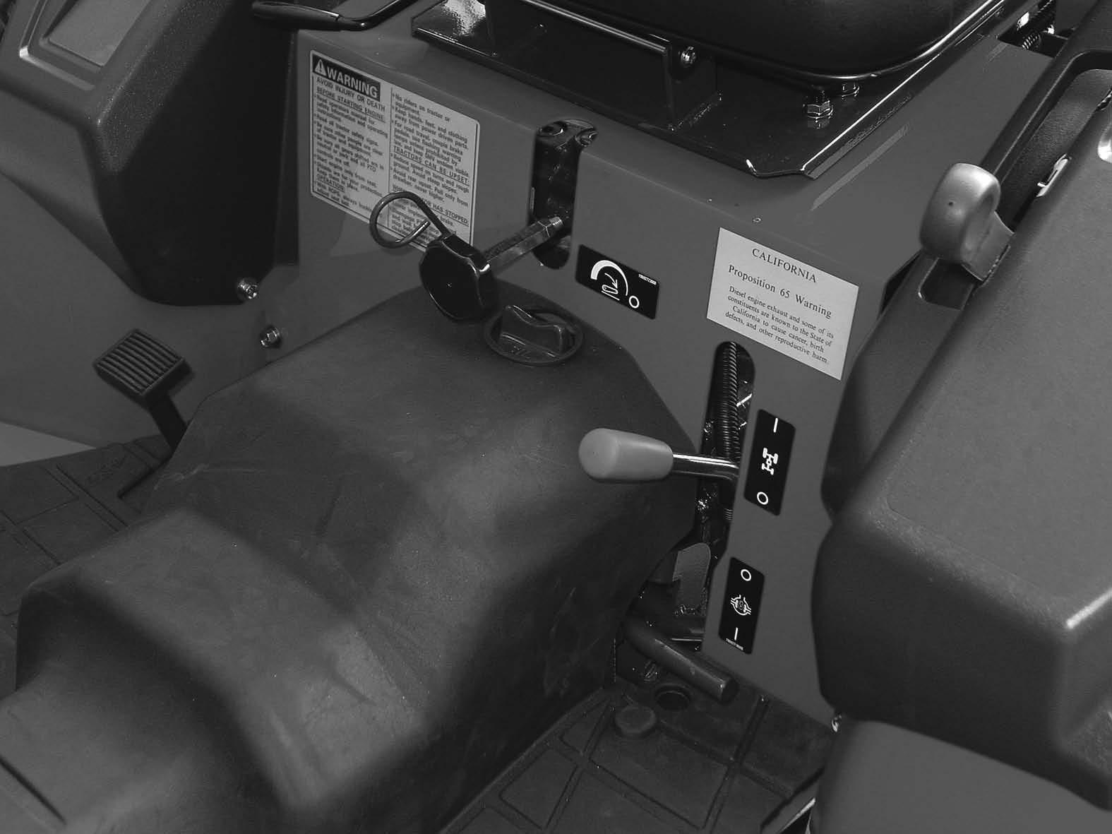
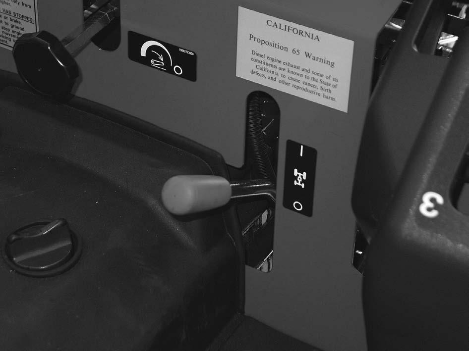
2. MFD CONTROL LEVER
To engage the MFD (Mechanical Front Drive), move the MFD control lever upward. Move the lever downward to disengage MFD (drive to the rear wheels only).
IMPORTANT: The clutch pedal must be pushed down to operate the MFD lever.
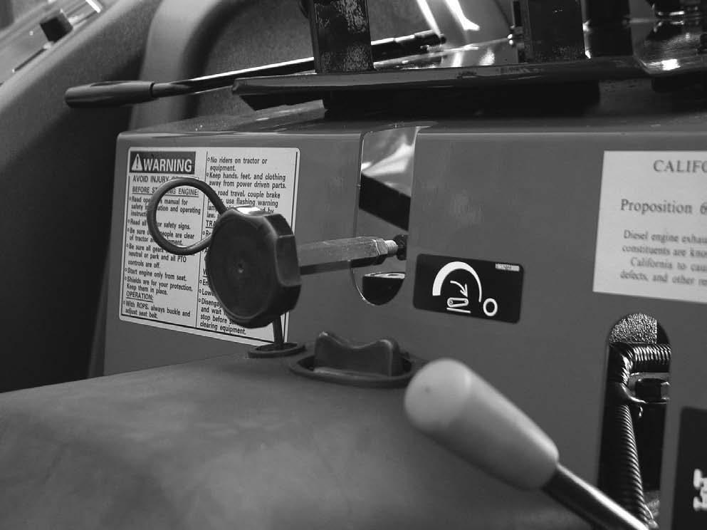
3. HYDRAULIC FLOW CONTROL KNOB
Use the hydraulic flow control knob to adjust the hitch lowering speed. Adjust the lowering speed to provide smooth operation of the hitch with the implement being used. Turn the knob fully clockwise to lock the hitch in position. See Hitch Lowering Speed Adjustment in this manual for more information.


