3 minute read
Controls


Differential Lock Pedal
This pedal located on the RH side of the operator's seat when depressed by heel pressure, operates a differential lock mechanism which locks both of the axle shafts together. Its purpose is to overcome the one-wheel slip encountered under bad field conditions, especially when ploughing or when hauling heavy trailers on slippery surfaces. Differential lock is designed for occasional use. Do not attempt to lock differential while, a. The tractor is in high speed. b. Turning tractor.

Releasing the pedal pressure disengages the differential lock.
Clutch / Inching Pedal
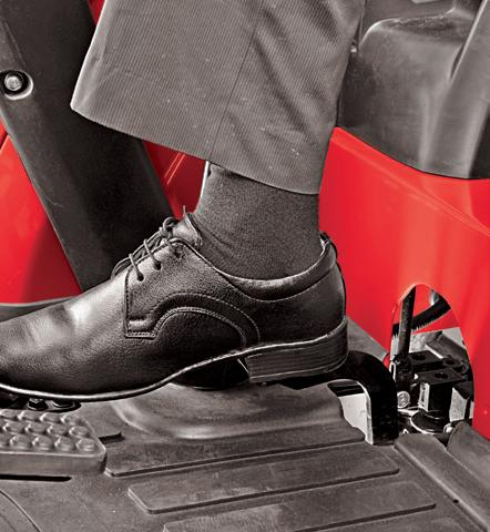
Tractor is fitted with hydraulic control valve to engage / disengage drive to transmission. For independent PTO aseparate hydraulically operated clutch pack is mounted on the PTO shaft. Main clutch gives drive to the transmission and is operated by clutch pedal.
Depressing the clutch pedal fully disengages the drive to gear box for selection of different speeds.
The differential lock design is solely for the use with pneumatic tires. If steel wheels, girdles etc. are fitted, the differential lock should be removed as a precaution.
Attempting to turn the tractor while differential lock is engaged may result in damage to transmission.

This tractor is equipped with Dual PTO option, namely 540 and 540E.
To select required PTO rpm, shift the lever and put it in required position.


PTO will not be operable in case of Neutral position.
540

With 540 position selected and the engine running at the indicated speed, the PTO shaft will rotate at 540 rpm. 540E
540E is an economy mode that allows the PTO to rotate at 540 rpm with a lower engine speed.
The free play of the PTO clutch is preset at factory. It is not recommended to adjust the same through PTO clutch linkage.
NOTE :
The clutch may require replacement due to normal wear, if loss of power to PTO shaft is observed when PTO lever is engaged. Your local Mahindra dealer should identify and rectify the issue.
When PTO drive is not in use keep the PTO lever in disengaged position.
Firmly apply the parking brakes, place all gear shift levers in neutral and block all four wheels before operating any stationary PTO equipment
Do not approach or work on the PTO shaft or equipment while the PTO is in motion. Shut-off engine and the PTO and wait for all movement to stop before working on the PTO or equipment.
Controls
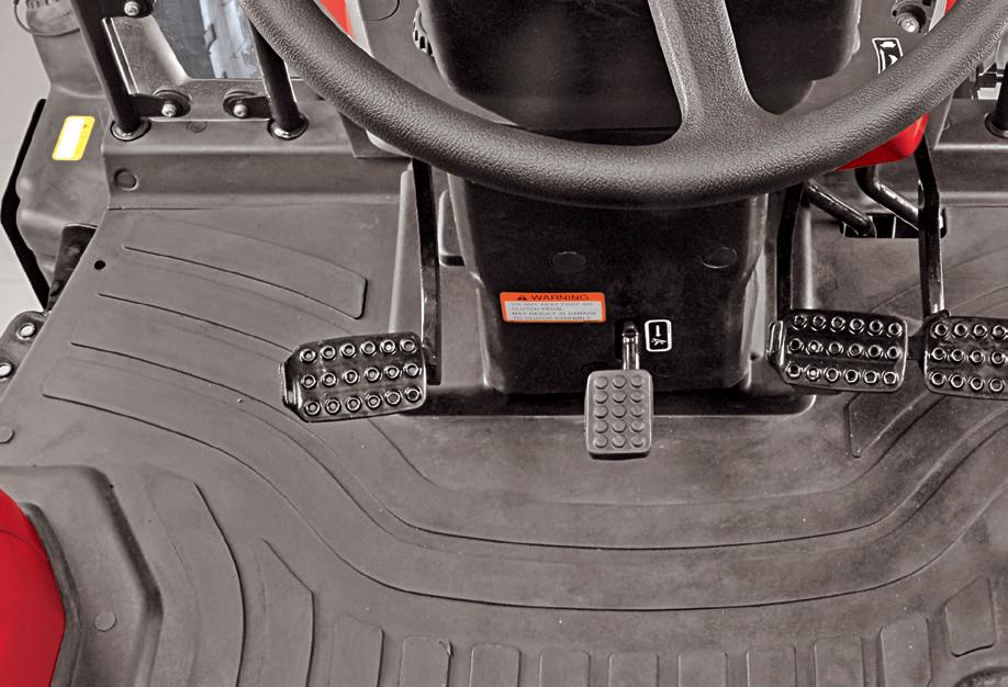
Range Shift Lever
This lever is located on L.H side of operator’s seat. This lever has three positions as follows,
1. Low – for Low speed range
2. Neutral
3. Medium – for Medium speed range
4. High – for High speed range
This lever enables 3 different speed options for every Speed Gear selection. The lever can be engaged as follows,
1. Depress Clutch pedal and stop tractor motion completely.
2. Choose High / Medium / Low speed range to match work application.
3. Release clutch pedal gradually. Refer Chart for road speed of tractor in different positions.
Never shift Range shift lever while the tractor is in motion.
Tractor road speed in different positions of F-R Shuttle, Range and Speed Levers.
F-R Shuttle Shift Lever
This lever is located on L.H side of Steering. This lever enables to choose the direction of tractor motion and has three positions as follows,
1. Forward – for forward motion of tractor.
2. Reverse – for rearward motion of tractor.
3. Neutral


The lever can be engaged as follows,
1. Lift the Forward / Reverse shuttle shift lever from its neutral position and shift to choose Forward or Reverse mode as desired.
2. Forward / Reverse shifts can be made without depressing clutch pedal at any speed.

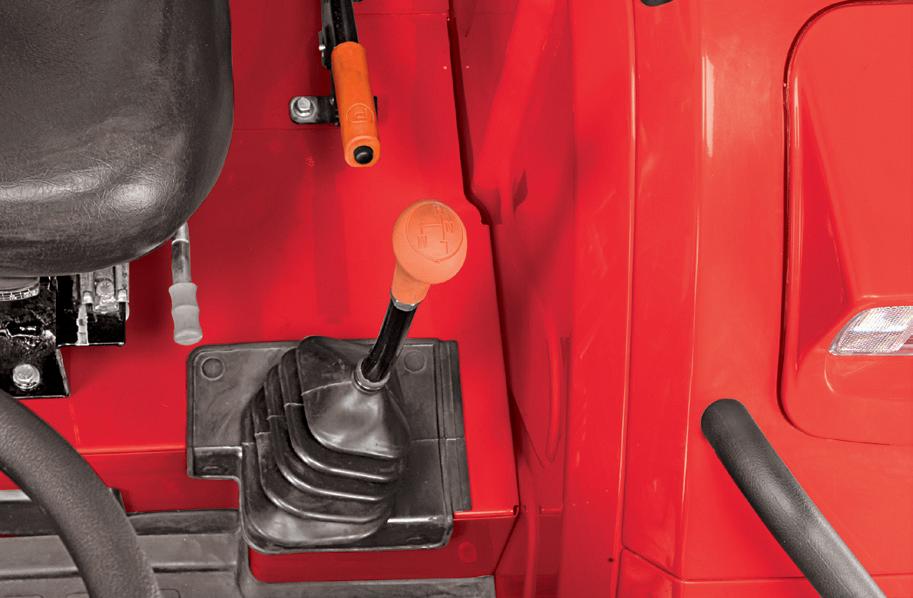
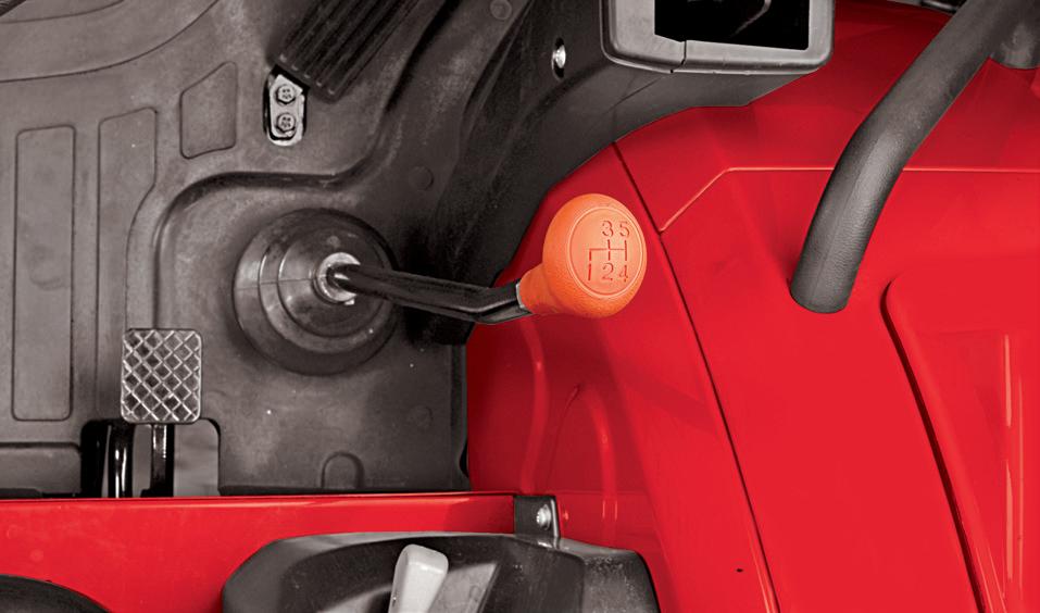
Speed Shift Lever
This lever is located on RH side of operator's seat. This lever has six positions. This lever enables 5 different speed options within a particular "Range Gear" selection. The road speed increases in higher gears.
1. Depress Clutch pedal completely.
2. Choose any one gear to match work application.
3. Release clutch pedal gradually. The gears can be shifted on-the-go. Refer speed chart (page-48) for road speed of tractor in different positions.
Auxiliary Valve
The auxiliary valve is equipped with 2 lever operated valves. Each valve has four positions as follows : a. Float (F) Detent b. Lower (L) Detent c. Neutral (N) d. Raise (R) Detent
The lever returns to neutral position from lower or raise position when the cylinder is fully retracted / extended. Keep the levers in neutral position (N) when auxiliary valve is not in use.