
7 minute read
Switches


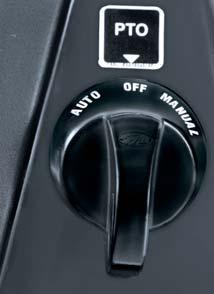
3.Alignment of Manual-mark with pointer - Operates Manual mode
This switch can be used when the “PTO Engage - Disengage Switch” is in ON position.
Keeping this switch in MANUAL-POSITION, will FORCE the PTO shaft rotation in RAISED as well as LOWERED position of implement. The “PTO Engage - Disengage Switch” will be CONTINUOUSLY-GLOWING when this switch is in MANUAL mode.
Power Take Off
PTO is operated electrically. PTO can be operated by using a combination of “PTO Engage - Disengage Switch” and “PTO Mode Switch”.
After switching ON the “PTO Engage - Disengage Switch” the operator has a CHOICE to select AUTO or MANUAL MODE through “PTO Mode Switch”.
The PTO will turn-Off if the “PTO Engage - Disengage Switch” or “PTO Mode Switch” is in OFF position.
Refer table shown for combinations of PTO Operations.
PTO ON/OFF Switch
PTO Control Switch
PC
ONManual ModeEither raised or
While the PTO is in MANUAL-MODE, some inadvertent movement of personnel near the PTO shaft can prove fatal.

Controls
Operator Seat

The operator seat can be adjusted for position, tilt and weight of operator. These adjustments are to be done prior to starting the engine.

Adjusting Seat Position
1.Sit on the operator seat.
2.Push the lever (D) upwards and slide seat forward or rearward to desired position.
3.Release Lever to lock seat in position. Ensure that all controls can be accessed easily.
Weight Adjustment
To achieve optimum seat suspension, turn the knob (B) till the weight indicator indicates your approximate weight on indicator (C).
Tilt Adjustment
To achieve optimum seat tilt, turn the knob (F) till the desired angle of tilt is achieved.

Using Seat belt
Use a seat belt when you operate with Roll over protective structure (ROPS) to minimise chance of injury from an accident such as an overturn.
Fasten Seat belt
1.Pull belt end (A) across operator lap.
2.Install tab into buckle (E). A click will be heard when the tab locks into the buckle.
Release Seat belt
Press red button (G). The seat belt will automatically retract.
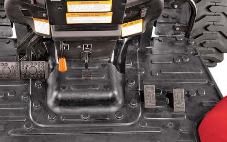
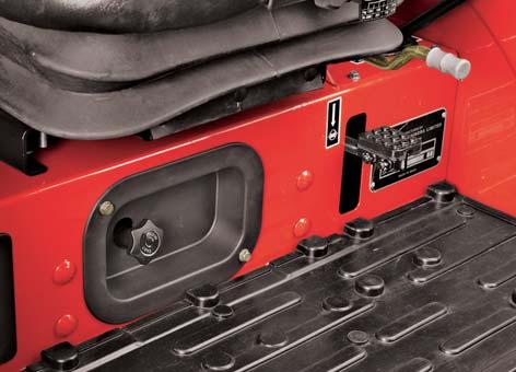
Slow Fast Valve Control Knob
3 Point Linkages drops faster when a heavy implement is attached. Adjust Slow/Fast Valve Knob (H) so that it is slow enough to be safe and prevent damage.
Turn the Slow/Fast Valve Knob, located on rear platform besides differential lock pedal, clockwise to slow rockshaft drop.
This knob is also called implement lock. When the knob is fully tightened in, implement will not lower down even if position control lever is fully down. Use implement lock while transporting implement.
Attempting to adjust the seat while driving the tractor may cause the operator to lose control of the tractor
Do not use seat belt if operating without a ROPS or ROPS in the folded position.
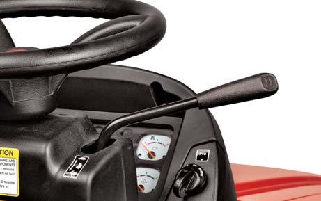
Hand Throttle Operation
Use the Hand Throttle Lever to set a constant engine speed for stationary operation or for field operation wherever desired.
Increasing Engine Speed : Pull throttle lever towards operator as indicated in the sticker on the dashboard.
Engine Tachometer Speeds : a.Low Idle speed - 1000 RPM b.Rated engine speed - 2800 RPM c.High Idle speed - 2975 RPM


Decreasing Engine Speed : Push throttle lever away from the operator as indicated in the sticker on the dashboard.
Constant Speed Setting : Certain operations may require a particular engine speed. This can be achieved by resting the Hand Throttle Lever in a position where you get the desired engine speed.
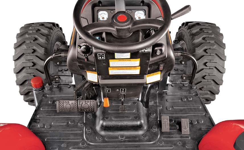
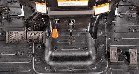
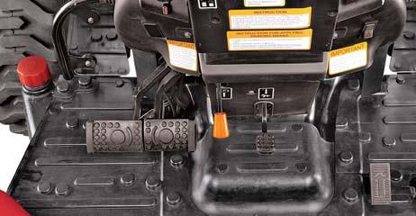
Forward-Reverse Operation
The tractor is equipped with two pedals to change the direction of travel. Depress the forward pedal (rubber cover showing arrow towards front of tractor) to move forward. Depress the reverse pedal (rubber cover having arrow mark towards rear of tractor) to move backwards.
Can Holder
A Can holder is located on RH side of fender.
Glove Box
A small utility box is located on LH side of fender.
Controls
Tilt Steering
The steering can be tilted towards the operator as per the need and convenience of operator and is recommended to be done in tractor parked condition.
Tilt Adjustment
1.Park the tractor safely.
2.Press the Tilt steering pedal by foot.
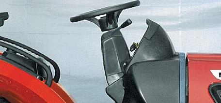
3.Pull the steering wheel to desired position.
4.Release foot pressure on the pedal.
5.To position the steering wheel back, press the tilt steering pedal to allow the steering wheel to travel back to the top position. It will go back automatically.
4WD Engagement Lever
This lever is located on LH side of operator’s seat. It is used to engage or disengage the drive to front wheels and is recommended to be done in tractor stand still condition.
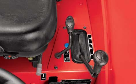
1.Stop the tractor motion completely.
2.Lift the lever upwards to engage the drive.
3.Push the lever down to disengage the drive.
Attempting to adjust the steering wheel while driving the tractor may cause the operator to lose control of the tractor.
Lock the steering wheel in position before driving the tractor.
Disengaged Position
Do not engage or disengage the 4WD Engagement lever while the tractor is in motion.
Brake
Two independent brake pedals are provided on left side of the operator for LH and RH wheel braking to enable sharp turns during field operations.
To make a sharp turn to the left, depress LH brake pedal (A).
To make a sharp turn to the right, depress RH brake pedal (B).
The brakes can be latched together to act simultaneously by means of brake pedal latch (C) as follows,
1.Rotate brake pedal latch (C) clockwise until it locks into RH brake pedal (B).
2.When brakes are applied with brake pedals latched together, the tractor should stop in a straight line. Check and adjust brake settings if the tractor is dragged to either side on applying brakes.
The Hand Throttle Lever should be brought to low idle rpm position before applying brakes.
Using unlocked brakes to stop the tractor at high speeds may cause accidental turning or tipping. Lock pedals together when not using the turn brakes or for road travel.
Slow down before making a turn.
Do not apply independent brakes while an attachment is engaged with the ground. This can cause damage to the attachment , three point linkage of tractor and may also result in tipping of the tractor.
Parking brake
The Parking brake lever is provided in front of operator’s seat.
Locking :
1.Lock both brake pedals together by using latch.
2.Press the brake pedals by foot.
3.Pull park brake lever completely upwards to the lock position and hold it.
4.Remove foot from the brake pedals. Both pedals should now stay depressed in locked position.
5.Parking brake indicator lamp will glow when key switch is 'ON'.
Unlocking :
1.Press the brake pedals with foot.
2.The park brake lever will spring back to unlock position.
3.Remove foot from the brake pedals. Both pedals should now be released from the lock position.
Always ensure to unlock parking brake before driving the tractor. Check for indicator lamp on the instrument cluster when the parking brake is released. The indicator light should be 'OFF'.
The brake pedals for this tractor are provided on the LH side. While getting down from the tractor LH side, after applying parking brake, get down slowly and ensure that the brake pedal do not get pressed and disengaged the parking brake. When parking on a slope, ensure that the vehicle is parked across the slope.
To
avoid personal injury : Before dismounting the tractor,
Always apply the parking brake and lower all implements to the ground. Leaving the transmission in gear with engine stopped will not prevent the tractor from rolling.
Differential Lock Pedal

This pedal located on the LH side of the Operator's Seat when depressed by heel pressure, operates a differential lock mechanism which locks both of the axle shafts together.
Its purpose is to overcome completely one-wheel slip encountered under bad field conditions, especially when plowing or when hauling heavy trailers on slippery surfaces.
The condition where one wheel spins completely uselessly digging itself Into the soil while the other stands idle, is thus overcome resulting in saving fuel, brake wear and tire abuse.
Differential lock is designed for occasional use. Do not attempt to lock differential while, a.The tractor is in high speed. b.Turning tractor.
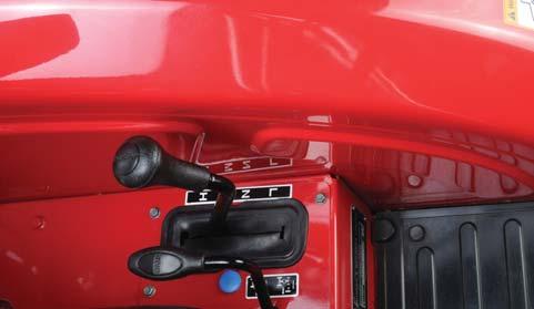
Range Shift Lever
It is located on LH side of operator’s seat. This lever has 4 positions as follows.
1.Low- For low speed range
2.Neutral
3.Medium- For medium speed range
4.High- For high speed range speed range
This lever enables 3 different speed ranges. It can be engaged as follows,
1.Choose High / Medium / Low range to match work application.
Refer Specification for road speed of tractor in different ranges.
The Differential Lock design is solely for the use with pneumatic tires. If steel wheels, girdles etc. are fitted, the differential lock should be removed as a precaution.
Attempting to turn the tractor while differential lock is engaged may result in damage to transmission.
Never shift Range shift lever while the tractor is in motion.
Cruise Control Lever
Cruise control is designed for tractor efficiency and operator comfort. This device will provide a constant forward operating speed by mechanically holding the cruise control lever at the selected position.

To engage cruise control lever :
1.To move the tractor in forward direction at any required speed, move the cruise lever forward and set it at any position.
2.To travel faster than the set speed, depress the forward pedal further down in this condition. The set speed will resume if the pedal is released.
To disengage cruise control lever :
1.Move the cruise lever all the way backwards till it stops to disengage the cruise control.
2.Depressing both brake pedals together will also disengage the cruise lever.
The cruise lever will not disengaged if the brake pedals are applied independently. Both brakes should be latched together while using the cruise control feature.
The cruise control feature is provided for forward motion only. Do not try to set the cruise lever while moving the tractor in the reverse direction as it will cause the tractor to stop moving suddenly.
Hydraulic Remote (Auxiliary Valve) Operation
The hydraulic remote is a single spool, double acting type hydraulic control valve. It is provided with an operating lever which is located towards the right side of the operator seat. The lever has three positions.
1.To direct the hydraulic oil flow to ‘A’ Port, move the lever in the forward direction (F).
2.To direct the hydraulic oil flow to ‘B’ Port, move the lever in the backward direction (B).
3.The lever will return to neutral position (N) when it is released at forward or backward position.


