2 minute read
Body Builder Connections

from Mack Truck Electrical Wiring & Connections CHU CXU GU TD MRU LR Body Builder Instruction Manual PDF
LR Control Link II
The body builder connector can be accessed by removing the panels on the center console. The suggested routing path for upfitters is not a physical component provided with the vehicle. It’s purpose in the illustration is to indicate the suggested wiring routes for upfitter harnesses. For convenience, MACK provides a pair of rubber grommets located behind the driver seat. This is the pass-through area which leads beneath the cab.
Advertisement
W9096945
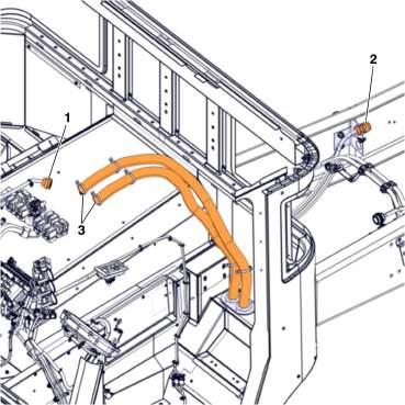
Fig. 19 Control Link II, 9-pin Lighting Connector, Wire Insertion Side of Connector
Pin Chart for Control Link II 9-pin Lighting Connector
DCL Connector (LR/MRU) or Connector X21A (LR)
ON/OFF Switch
Spare SW.3 / PTO 3
PTO 2
VECU SW Input
ON/OFF Switch
PTO 1
Accel
EMS Power 1 CB18
Spare Relay 2 / PTO 4
Spare SW.2 / PTO 4
Spare Relay 1 / CDS 1 OUT / PTO 3 (MRU Only; unused on LR)
Engine Stop/Spare Switch
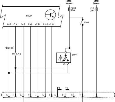
MRU/LR DCL Connections
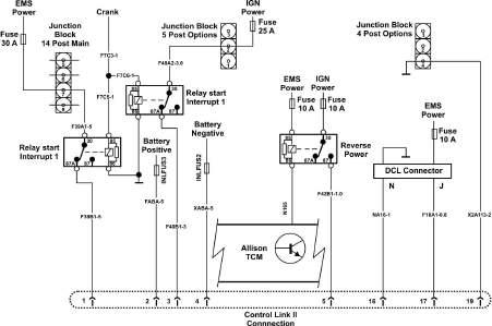
Figures 18 and 21 show DCL connections which are available on all Conventional models. Figures 16 and 22 show DCL connections for MRU/LR. The availability of these is limited as they are used for mDrive, ACC, Aux Fan and other options. However, when available they can be used for more complicated controls such as secondary enable of engine speed control or as configurable PTO output.
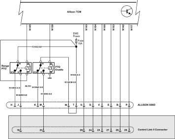
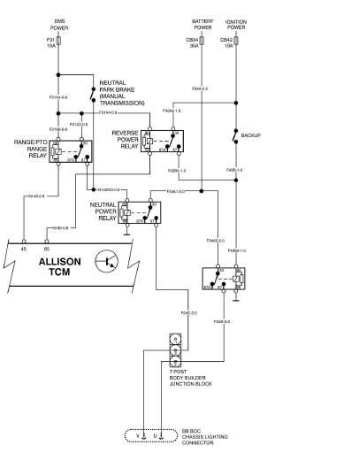
Allison Connections
MRU/LR Control Link II has many Allison connections included. Conventional BodyLink does not. However, all trucks with Allison Transmissions include a connector (X06D) to access Allison functions directly
Note: * Shaded section on MRU / LR only
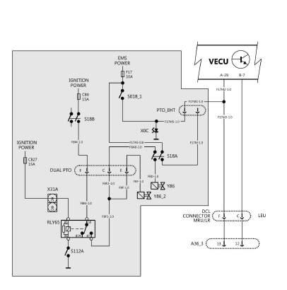
PTO and Engine Speed Control Connections
MRU and LR have several specific wiring options for PTO that don’t necessarily affect engine speed control. However the Control link II connection offers access to inputs to affect engine speed control based on PTO activation or other equipment inputs.
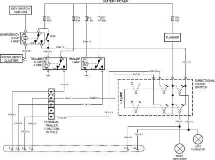
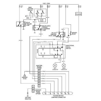
Lighting Connections
MRU/LR Control Link II has lighting connections in a separate BOC connector whereas Conventional has lighting connections in the Body Link connector which is also BOC. These are nominally lighting outputs but can also be used for control. Note than Neutral and Reverse are also in the MRU/LR Control Link II Connector
Notes
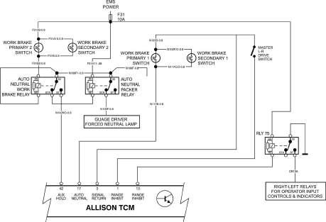
LR Workbrake
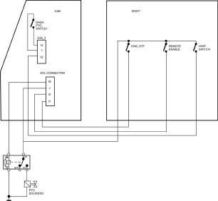
The Mack has a workbrake which operates pneumatically like a service brake. It is also tied into Allison inputs to effect a forced neutral. The Allison also has some conditions to allow switching driving positions so that loss of throttle and transmission control don’t happen while moving.
Notes
Summary
Figure 31 shows examples of what the control pins could be used for in an application. The PTO inputs are programmable and can affect a conditional output, engine ramp, engine limits, etc. See programming section for details. Note that full safety evaluation of the system should be carried out. I.E., adequate interlocks should be programmed or wired, so that the engine will not accelerate in unintended situations. Interlocks can be done by powering switches using switched power (for example neutral power) or by software parameters or both. For example, most applications should only have the engine ramp using body controls when the park brake is on and the transmission is in neutral. Exceptions should be carefully considered..
Notes