2 minute read
Termination Resistor

from Mack Truck Electrical Wiring & Connections CHU CXU GU TD MRU LR Body Builder Instruction Manual PDF

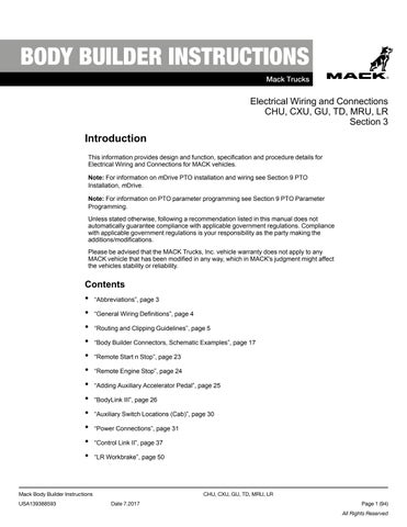
W3005518
Termination Resistor, 2–pin
Termination Resistor – J1939
Termination resistors are wired to each end of the SAE J1939 data link to prevent signal reflections. They must remain connected for the data link to function properly. The resistance value of each termination resistor is 110–130 Ω. When properly installed in the data link, their combined resistance is 50–70 Ω since they are connected in parallel.
The termination resistor at one end of the SAE J1939 data link is located in the fuse/relay center (FRC) near the vehicle electronic control unit (VECU) and the other near the engine control module (ECM). On vehicles equipped with MACK engines, the termination resistor at the engine end is located inside the ECM. On vehicles equipped with Cummins engine, the termination resistor is located in the harness area just outside of the ECM.
A SAE J1939 data link connection is located at the transmission area in the chassis harness. On vehicles equipped with an electronically controlled transmission (Allison/Autoshift II/Meritor Freedom Line), the connection to the transmission is located at the chassis harness. On vehicles equipped with a manual non-electronically controlled transmission - the connector stub will have an un-terminated blanking plug installed.
Only two termination resistors are used in each data link. Never install more than two terminator resistors in one data link. If more than two resistors exist in the SAE J1939 data link circuit, incorrect or absent signals may occur You can easily check to see if you have two resistors by measuring the resistance between pin C and D for the 9-pin diagnostic connector, or pin 3 and 11 for the 16-pin diagnostic connector, with the ignition key in OFF position. The correct resistance is 50 – 70 Ω. The termination resistors should each have a resistance of 110 – 130 Ω when tested individually
Termination Resistor – ISO 14229
Termination resistors are also wired for the ISO 14229 data link. One resistor is located in the engine control module (ECM). The other is a two pin resistor located in the dash close to the diagnostic connector The diagnostic connector is located on the driver ’s side lower dash panel. Termination resistors must remain connected for the data link to function properly. The resistance value of each termination resistor is 110–130 Ω. When properly installed in the data link, their combined resistance is 50 – 70 Ω since they are connected in parallel
The termination resistor at one end of the ISO 14229 data link is located in the fuse/relay center (FRC) near the vehicle electronic control unit (VECU) and the other near the engine control module (ECM). On vehicles equipped with MACK engines, the termination resistor at the engine end is located inside the ECM.
A ISO 14229 data link connection is located at the transmission area in the chassis harness. On vehicles equipped with an electronically controlled transmission (Allison/Autoshift II/Meritor Freedom Line), the connection to the transmission is located at the chassis harness. On vehicles equipped with a manual non-electronically controlled transmission - the connector stub will have an un-terminated blanking plug installed.
Only two termination resistors are used in each data link. Never install more than two terminator resistors in one data link. If more than two resistors exist in the ISO 14229 data link circuit, incorrect or absent signals may occur You can easily check to see if you have two resistors by measuring the resistance between pin 3 and 11 for the 16-pin diagnostic connector, with the ignition key in OFF position. The correct resistance is 50 – 70 Ω. The termination resistors should each have a resistance of 110 – 130 Ω when tested individually