2 minute read
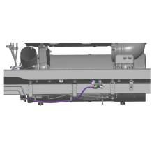
NOx Sensor Routing

from Mack Truck Electrical Wiring & Connections CHU CXU GU TD MRU LR Body Builder Instruction Manual PDF

The NOx sensor requires unique routing considerations. The NOx sensor harness must not be bundled with other wiring harnesses. However, it may be routed with other harnesses as long as they are not high voltage cables. The sensor harness is a set length and no altering or modifying of the NOx sensor harness is allowed.
Note: DO NOT splice into a V-MAC, ABS/ATC or any other electronic control unit harness. Do not cut or tap into the J1939 green/yellow twisted wires or any other wire or harness used on this vehicle. Use the provided connectors, and only add approved J1939 components with validated software. Failure to comply may result in personal injury or equipment damage. Any cutting, splicing, alteration or modification to the wiring will Void the Mack Trucks Warranty on the Electrical System.
Body Builder Connectors, Schematic Examples
Third party devices are often installed on MACK trucks. These devices need information (vehicle speed, gear, etc.) to operate safely and efficiently However these devices are not quality controlled as far as MACK is concerned, and are not part of the main control databus. Therefore, MACK provides an external connector to supply a body device with the necessary information it needs to function properly.
MACK trucks do not use an external body builder module (BBM). In MACK trucks, the functions of the BBM are managed by the Vehicle Electrical Control Unit (VECU) and are transmitted to the body device via an SAE J1939 connector SAE J1939 is a communications link between standalone vehicle modules. This data link is commonly referred to as the “Control Data link”. It is used primarily to transmit control signals that are shared between other standalone modules. The information on the SAE J1939 control link is used for control functions. Fault messages or diagnostic information also transmits across this link. These control signals may be for engine, transmission, brakes or a number of other vehicle control needs. The J1939 operates at 250,000 bits per second, which is approximately 26 times faster than the J1708/1587 data link. This higher speed allows the system to operate at a faster sampling rate and higher resolution, thus enabling better control of vehicle functions.
Terminating Resistors
Terminating resistors are wired to each end of the SAE J1939 data link to prevent signal reflections. They must remain connected for the data link to function properly The resistance value of each termination resistor is 110–130 Ω. When properly installed in the data link, their combined resistance is 50–70 Ω since they are connected in parallel.
The termination resistor at one end of the SAE J1939 data link is located in the fuse/relay center (FRC) near the vehicle electronic control unit (VECU) and the other near the engine control module (ECM). On vehicles equipped with MACK engines, the termination resistor at the engine end is located inside the ECM. On vehicles equipped with Cummins engine, the termination resistor is located in the harness area just outside of the ECM.
A SAE J1939 data link connection is located at the transmission area in the chassis harness. On vehicles equipped with an electronically controlled transmission (Allison/Autoshift II/Meritor Freedom Line), the connection to the transmission is located at the chassis harness. On vehicles equipped with a manual non-electronically controlled transmission - the connector stub will have an un-terminated blanking plug installed.
Only two termination resistors are used in each data link. Never install more than two terminator resistors in one data link. If more than two resistors exist in the SAE J1939 data link circuit, incorrect or absent signals may occur You can easily check to see if you have two resistors by measuring the resistance between pin C and D for the 9-pin diagnostic connector, or pin 3 and 11 for the 16-pin diagnostic connector, with the ignition key in OFF position. The correct resistance is 50 – 70 Ω. The termination resistors should each have a resistance of 110 – 130 Ω when tested individually.