7 minute read
BODY BUILDER INSTRUCTIONS

from Mack Truck Electrical Wiring & Connections CHU CXU GU TD MRU LR Body Builder Instruction Manual PDF

Mack Trucks
Electrical Wiring and Connections
CHU, CXU, GU, TD, MRU, LR
Section 3
Introduction
This information provides design and function, specification and procedure details for Electrical Wiring and Connections for MACK vehicles.
Note: For information on mDrive PTO installation and wiring see Section 9 PTO Installation, mDrive.
Note: For information on PTO parameter programming see Section 9 PTO Parameter Programming.
Unless stated otherwise, following a recommendation listed in this manual does not automatically guarantee compliance with applicable government regulations. Compliance with applicable government regulations is your responsibility as the party making the additions/modifications.
Please be advised that the MACK Trucks, Inc. vehicle warranty does not apply to any MACK vehicle that has been modified in any way, which in MACK's judgment might affect the vehicles stability or reliability
Contents
• “Abbreviations”, page 3
• “General Wiring Definitions”, page 4
• “Routing and Clipping Guidelines”, page 5
• “Body Builder Connectors, Schematic Examples”, page 17
• “Remote Start n Stop”, page 23
• “Remote Engine Stop”, page 24
• “Adding Auxiliary Accelerator Pedal”, page 25
• “BodyLink III”, page 26
• “Auxiliary Switch Locations (Cab)”, page 30
• “Power Connections”, page 31
• “Control Link II”, page 37
• “LR Workbrake”, page 50
• “Wiring J1939”, page 52
• “9-pin Diagnostic Connector”, page 54
• “16-pin Diagnostic Connector”, page 55
• “Termination Resistor”, page 60
• “Parameter List”, page 61
• “Multiplexing Body Builder J1939 CAN ”, page 77
• “Support Inbound and Outbound J-1939 Message Information ”, page 85
Abbreviations
• ACC Adaptive Cruise Control
• BOC Back of Cab
• CAN Controller Area Network
• CDS Custom Defined Statement (replaced by DCL)
• DCL DataMax Control Language
• ECM Engine Control Module
• EHT Electronic Hand Throttle
• EMS Engine Management System
• ESC Engine Speed Control
• FMI Failure Mode Identification
• GMT Greenwich Mean Time
• MID Message Identifier (J1587 source)
• PGN Parameter Group Number (J1939 message ID)
• PID Parameter Identification (J1587)
• PID Product Identification (order code)
• PTO Power Take Off
• PTT2 Premium Tech Tool 2
• SA Source Address (J1939 unit identifier)
• SID Subsystem Identification (J1587)
• SPN Suspect Parameter Number (J1939 parameter)
• SSC Single Speed Control
• TCM Transmission Control Module
• VDA Vehicle Data Administration (OEM database)
• VECU Vehicle Electronic Control Unit
• V-MAC Vehicle Management And Control (Mack brand electronics name)
General Wiring Definitions
The general wiring definitions provides a standardized list of terminology used in running wires, hoses, and cables throughout the vehicle.
Abrasive Surface
Items capable of causing damage to the routed commodity in a rubbing condition during vehicle operation
AWG American Wire Gauge
Bundled With A number of items tied, wrapped, or otherwise held together
Cable Tie
Chafing
Contacts
Crimped
Damaged
A nylon plastic self-sizing strap, UV resistant, capable of bundling specified load(s) during vehicle operation
To wear away by rubbing
Items touching each other.
A routed commodity that is bent or pressed into ridges
An item that differs from its original condition
Drooping Routed items hanging downward which are detrimental to safe vehicle operation
Dual Fall
High Current Electrical Cables
(Pertaining to the Compressor Discharge Line) A high point in the routing of the Compressor Discharge Line (located on the engine) whereby any collected moisture is allowed to fall in two different directions where it is either dissipated by heat or is purged
Wire sizes 13 mm sq. (0.5 inches sq.) (6 AWG) and larger
High Nut Extended clamp length
Kinked A tight bend, curl, or twist in the routed commodity causing flow to be restricted
Low Current Electrical Cables Wire sizes 8 mm sq. (0.3 inches sq) (8 AWG) and smaller
Low Nut Standard clamp length
Material Grade 30 Minimum yield strength of 30,000 psi
Material Grade 50 Minimum yield strength of 50,000 psi
May Verb typically used in a statement of practice that is a permissive condition and carries no requirement or recommendation. It can be included to alter statements of mandate or recommendation
Not Secured
Plastic Conduit
Items not fastened, bundled or tied
Corrugated or smooth wall tubing used to protect hoses, harnesses, cables, tubing, pipes, etc.
Puncture Small hole or wound
Routed With
Rubbing
Items taking the same path but not attached to each other (i.e., parallel but separate)
Items that contact each other and have independent movement
Shall Verb typically used in a statement of required, mandatory or specifically prohibitive practice regarding routing and clipping
Sharp Edge A surface capable of cutting or piercing the routed commodity during vehicle operation
Should Verb typically used in a statement of recommended, but not mandatory, practice in typical situations with deviations allowed if Engineering judgement or Engineering study indicates the deviation is appropriate
Twisted
Distorted from the routed commodities’ original shape about it’s cross-sectional center line
Touch Items that contact each other but do not have relative movement
Routing and Clipping Guidelines
1 Brackets used in routing and clipping should be Material Grade 50 or better to ensure sufficient clamp load when sharing joint connections with cross members or other structural members. This applies only to joint connections using a low nut. Brackets of Material Grade 30 are acceptable provided the shared joint is using a high nut. The area of the clip bracket under the bolt head must be a least as large as the bolt head itself.
2 Clips that scratch exterior mounting surfaces shall not be used (i.e., barbed/spring type) unless the material is non-corroding (i.e., plastic). Clips must have rust protection.
3 Clip sizes should adequately secure the bundle without restricting flow, causing collapse, or preventing relative movement.
4 Bundles shall be supported at 24 inches (600 mm) maximum intervals, a cable tie should be used between clip points on bundles with the exception of electrical wiring harness which shall have a maximum support distance of 18 inches (450 mm) and a cable tie on bundles between clip points. When air and electrical lines are bundled together, the commodity with the greater cross sectional area may determine the support spacing. A minimum of two cable ties shall be used between clip points to bundle electrical lines when the larger interval is used.
W3104131
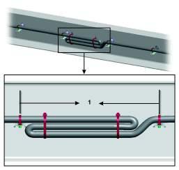
1 Support electrical cables every 18 inches (450 mm)
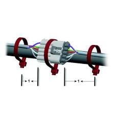
W3104144
1 Support cables near connectors every 4 inches (100 mm)
1 Electrical cables and wiring harnesses are to be secured 4 inches (100 mm) from the wire insertion end of the connector or clipped to the body.
2 Routing and clipping on purchased components (i.e., engine/transmission) should not include removing or replacing a bolt(s), nut(s) or screw(s) installed by the manufacturer In such cases where this is unavoidable, the bolt(s), nut(s) or screw(s) shall be re-installed to the manufacturer ’s specifications.
3 Bundles should not contact sharp edges of cross members. Contact may occur if it is against a smooth surface, a smooth radiused edge or a coined edge and the bundle is secured to prevent independent movement.
4 Hoses, tubing, pipes and electrical conduits shall not rub each other but may touch.
5 The fabric braided portion of the compressor discharge hose is compatible to be bundled with all routed air lines.
6 The compressor discharge pipe shall be routed independent of all other routing.
7 Electric cables/harnesses must not be bundled with fuel or hydraulic lines. The electrical cables/harnesses may be routed parallel with fuel or hydraulic lines, however must remain separated by approved clipping materials. When design control is possible, electrical cables/harnesses will be routed above fuel or hydraulic lines. If fuel or hydraulic lines must route above circuit protected electrical cables /harnesses, the fuel or hydraulic lines will have no fittings or potential leak points above electrical cables/harnesses and shall be minimized to the shortest distance possible over low current electrical cables/harnesses.
8 All associated markings on air and electrical harnesses should have a corresponding clipping apparatus.
9 Critical clipping locations shall be designated on the component to insure proper placement in the vehicle (i.e., tape).
10 Maximum support distance for compressor discharge rigid pipe, 30 inches (762 mm). Pipe to be isolated from support brackets (i.e. rubber isolator).
11 Maximum support distance for compressor discharge flex hose, 24 inches (600 mm).
12 Compressor discharge line should have a constant fall from compressor to air dryer A dual fall is allowable provided it occurs on the engine and within 24 inches (600 mm) of the compressor
13 Maximum allowable dip in compressor discharge pipe/hose is one half the outer diameter of the pipe/hose. Preferred routing should have no dips in any of the routing. This is to avoid line blockage due to water collecting and freezing in the line.
Heating Specifications
In order to maintain the integrity of the cables and hoses, observe the following specifications for routing near a heat source.
Cable, hose, or harness type
Electrical cables and wiring harnesses
Unprotected hoses, tubing, harnesses, and cables
Specification
5 inches (130 mm) in all directions from turbocharger, exhaust components, and other high heat components
6 inches (150 mm) above, 5 inches (130 mm) beside and 4 inches (100 mm) below Hoses, tubing, harnesses, and cables protected by reflective heat sheathing
3 inches (76 mm) above, 2 ½ inches (63,5 mm) beside and 2 inches (51 mm) below Silicone transmission coolant hoses
Hoses, tubing, harnesses, and cables protected by a heat shield (no reflective sheathing)
2 inches (51 mm) from exhaust manifold and turbo (with reflective heat sleeving), 1 inch (25 mm) from exhaust pipe
3/8 inch (10 mm) between the component and the heat shield. (Not valid for fuel lines)
Refrigerant suction hoses 8 inches (200 mm)
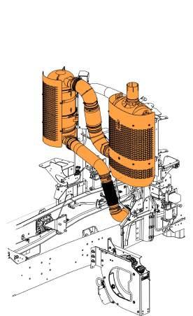
The SCR, DPF, and exhaust piping generate substantial heat. Keep electrical cables away from these components.
Clipping Guidelines
Clipping brackets should be designed and mounted to adequately support the bundle. Clips should be mounted in a hanging position or supported along three-quarters of the horizontal mounting surface. Orientations that do not conform to the illustrations shall be tested.
1 When hoses, wires, and cables cross one another, secure them with a clamp. This prevents the sawing motion that could abrade them.
2 When routing flex hoses that are bent in two planes, clip them to prevent twisting. Clamp the hose at the point where the hose changes planes. The clamp has the effect of dividing the hose into two assemblies. If the section of the hose is bent in the same plane as the movement, the bend will absorb the movement and the hose will not twist.
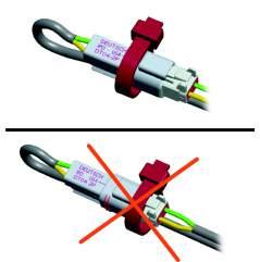
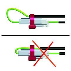
When routing connectors with cable ties, ensure the cable ties do not contact the connector locking tab. Cable ties should also not contact the bare wire.