7 minute read
WORKING EQUIPMENT

from Komatsu PC14R-3 PC14R-3HS PC16R-3 PC16R-3HS Hydraulic Excavator Shop Manual WEBM007801 PDF DOWNLOAD

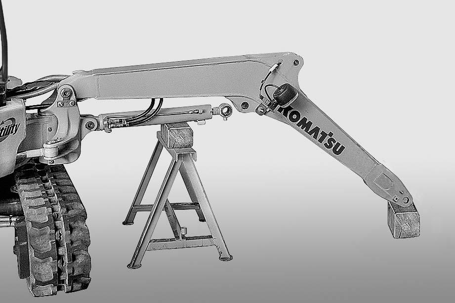
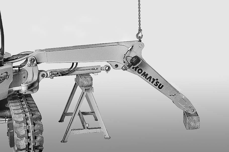
Removal k Fully extend the arm and open the bucket completely. Lower the equipment until it rests on the ground.
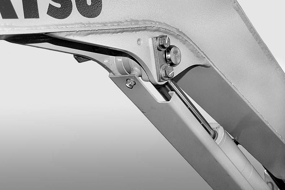
1 -Remove the protection (1) and the relative sliding shoes.[*1]
2 -Stop the engine, release all the pressure in the cylinder and de-pressurize the hydraulic system by moving the PPC valve lever several times.
3 -Remove the pin (2).[*2] a Note down position of any shims and direction of assembly.
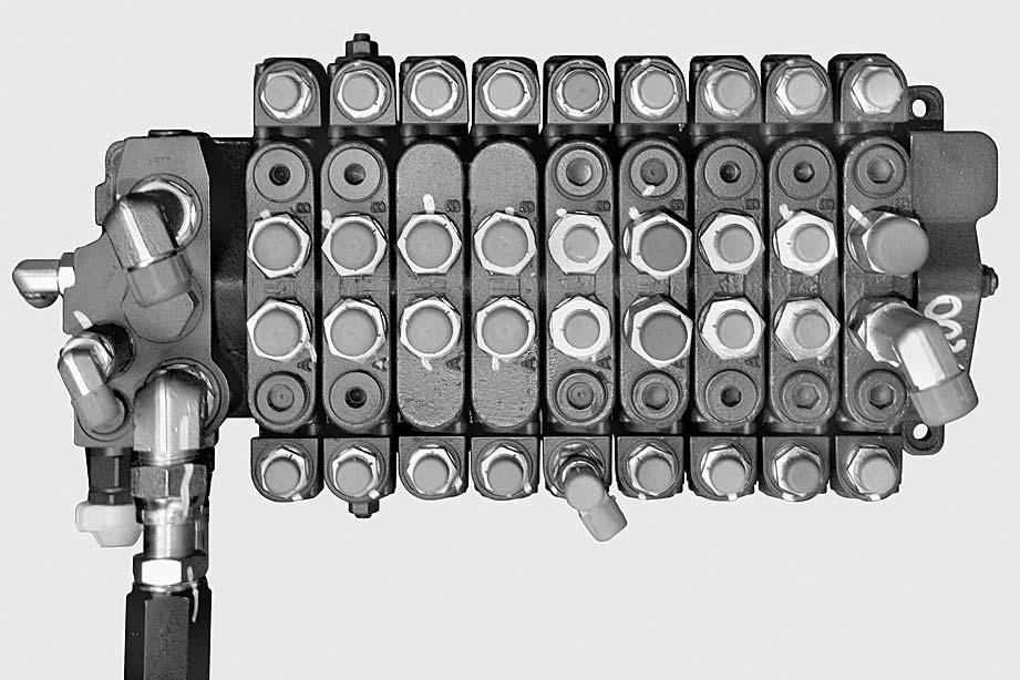
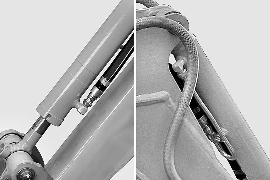
4 -Lower the cylinder (3) until it rests on a stand “A”.
5 -Start the engine to retract the piston.[*3] a Plug the tubes and fittings to prevent entry of impurities. a Mark the hoses to avoid exchanging them during reinstallation. a Adjust the length of the cables to balance the load. a Check and note down the position of any shims. [*4] k Remove and support the hoses and power lead of the work light during the removal procedure.
6 -Stop the engine and release the residual hydraulic pressures.
(For details, see "20 CONTROLS AND ADJUSTMENTS").
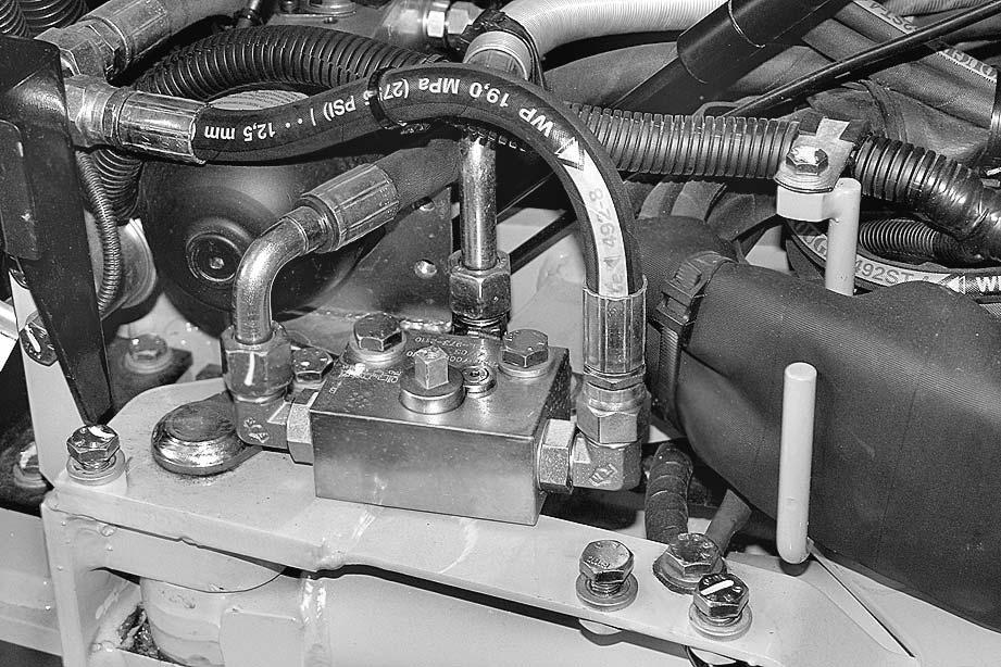
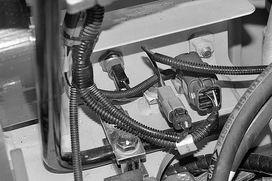
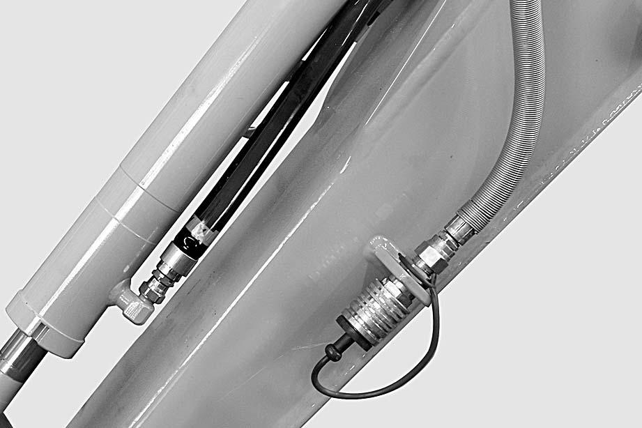
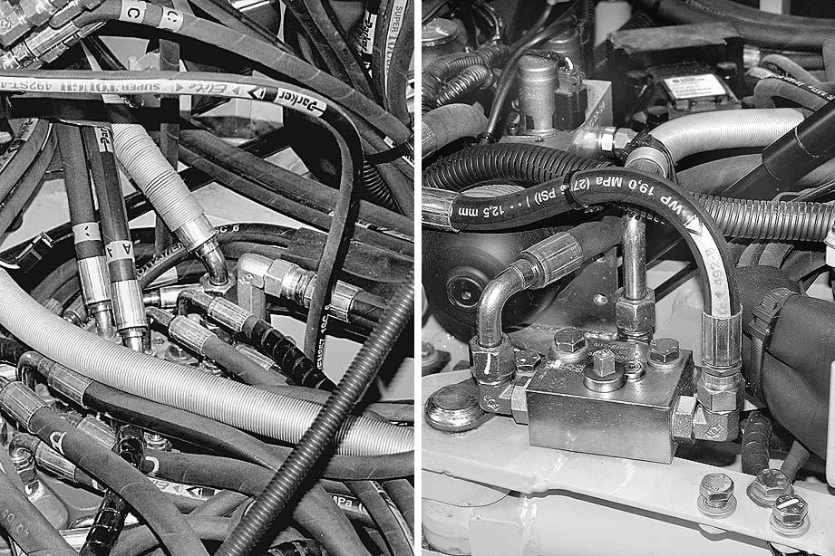
7 -Disconnect two arm hoses (4) (A -C yellow) and two bucket hoses (5) ( A - C green) from the control valve; plug the hoses and cylinder holes to prevent contamination.
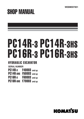
Only if equipped: Disconnect the optional equipment delivery hose (6) from the control valve and disconnect hose (8) from block (7).
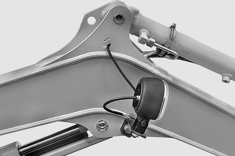
8 -Disconnect the connector (9) that supplies current to the working spotlight.
9 -Remove the working spotlight (10) complete with its bracket.
10 -Disconnect the connector (11) that supplies current to the working spotlight.
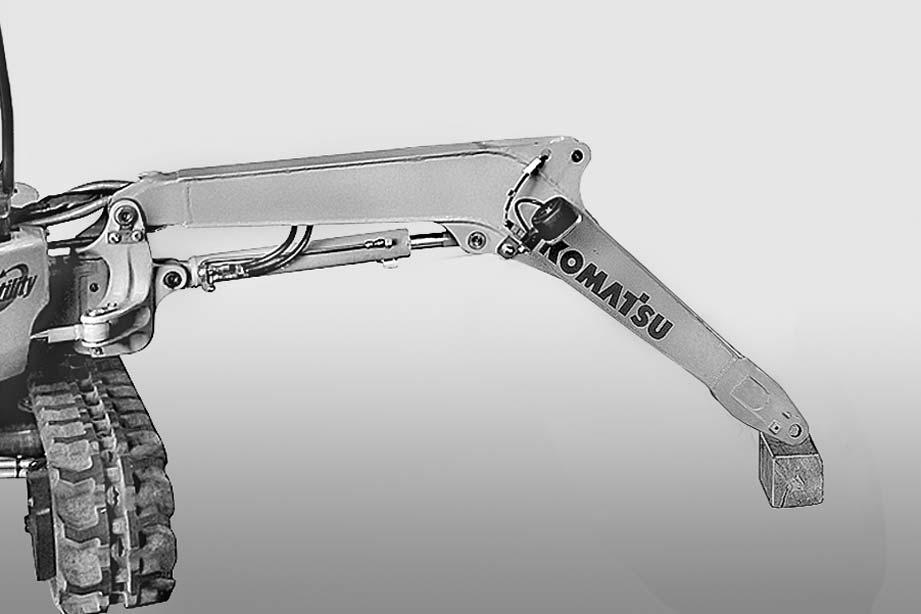
11 -Put a sling around the equipment and apply a slight tension to the cables.
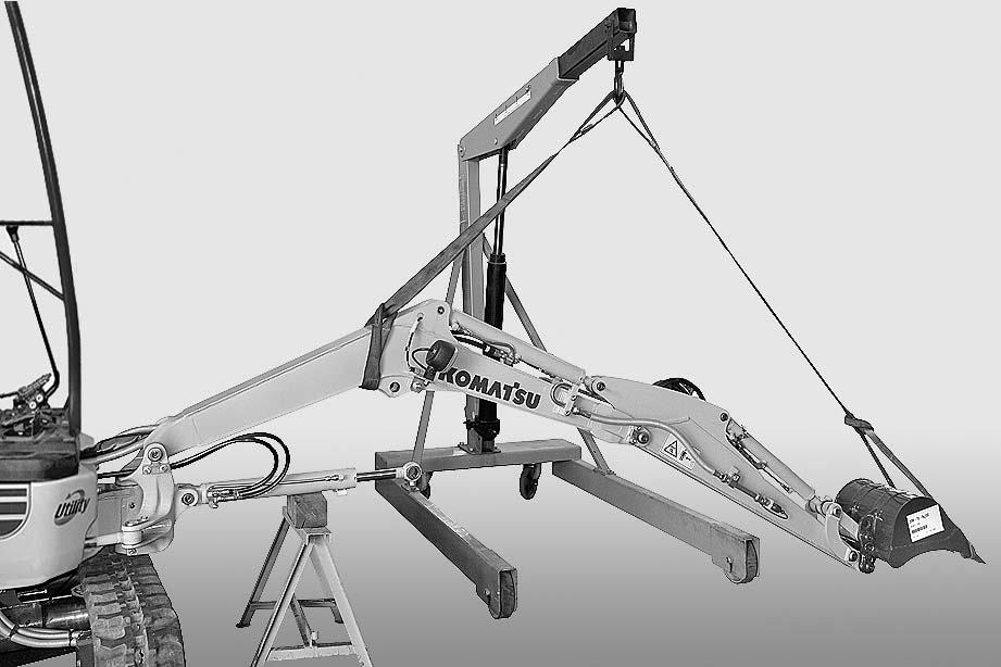
12 -Take away the pin (12). Remove the working equipment (13).
4 Working equipment: approx 130 kg
Installation
•To install, reverse the removal procedure.
[*1] a Check the centering and the smooth movement of the protection (1).
2 Shoes and guides: ASL800050
[*2]
[*3] a Insert the shims. kWhen aligning the positions between the hole and the pin, turn the engine over at low idling. Do not insert fingers in the holes to check alignment.
[*4] a Insert the shims.
2 Internal bushings: ASL800040 a When bleeding is complete, stop the engine. Check the oil level in the tank and pressurize the hydraulic system.
•Start the engine to circulate the oil and bleed the air from the cylinder.
(For details, see "20 CONTROLS AND ADJUSTMENTS").
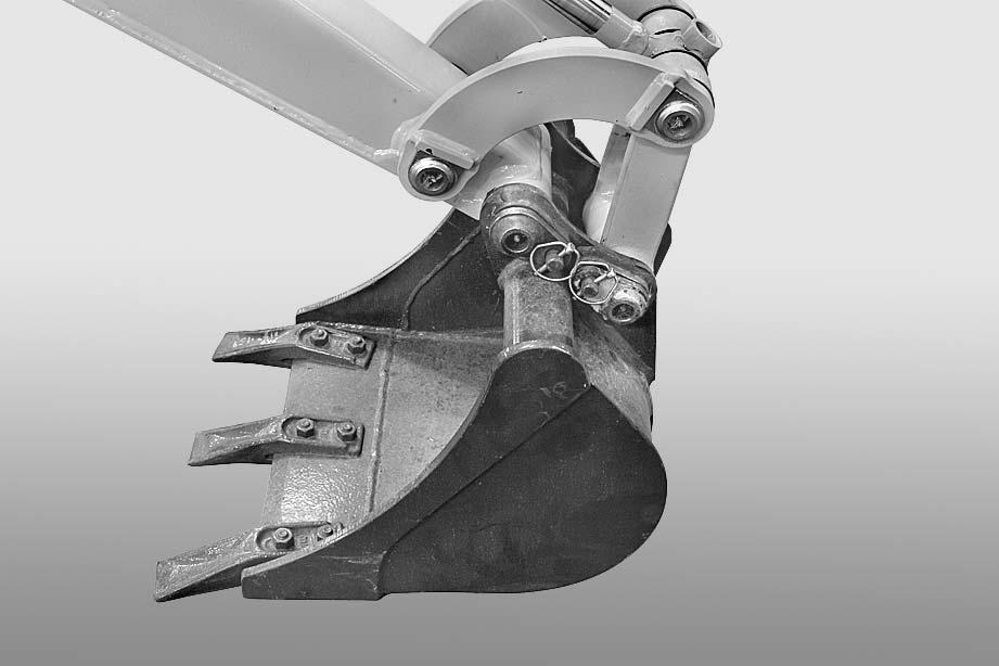
BUCKET Removal
kPosition the bucket on the ground on a flat surface, and resting on its back.
1 -Take out the safety pin (1) and remove the connecting pin (2) between the bucket (3) and the tie-rods (4).
[*1] [*2]
2 -Take out the safety pin (5) and remove the pin (6) that connects the bucket (3) to the arm (4).
[*1] [*2] a Collect the shims.
4 Bucket: approx 26 kg
Installation
•To install, reverse the removal procedure.
[*1] kWhen aligning the positions between the hole and the pin, turn the engine over at low idling. Do not insert fingers in the holes to check alignment.
[*2]
[*3]
2 Internal bushings: ASL800040 a Insert shims on both sides between the bucket (3) and the arm (7).
ARM Removal
1 -Remove the bucket. For details, see "BUCKET") a Plug the tubes and fittings to prevent entry of impurities.
2 -Remove the bucket cylinder. (For details, see "BUCKET CYLINDER").
3 -If the vehicle is designed to attach optional equipment at the front, disconnect the hoses (1) from ports (2).
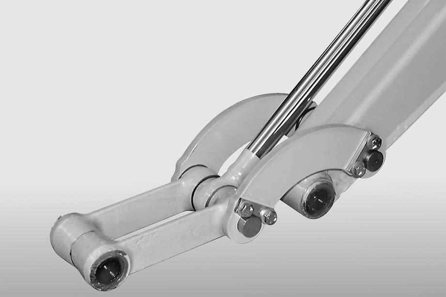
4 -Remove the pin (3) and the levers (4).[*1] [*2] [*3] a The links (5) are removed during the removal of the bucket cylinder. a Collect the shims.
5 -Position the arm (6) upright.
6 -Position a block B beneath the arm cylinder and remove the pin (7).
7 -Start the engine and completely retract the pist (8).
8 -Stop the engine.
9 -Connect the arm (6) to some hoisting tackle and apply a slight tension to the cable.
10 -Take out the pin (9).[*2] [*4] a Note down the location of any shims.
11 -Remove the arm (6).
4 Arm: approx 25 kg
4 Long arm: approx 30 kg
Installation
•To install, reverse the removal procedure. [*1]
2 Internal bushings: ASL800040 a Insert the shims. [*2] k
When aligning the positions between the hole and the pin, do not insert fingers in the holes to check alignment. [*3] a Install shims to both sides of the arm. k
When aligning the positions between the hole and the pin, turn the engine over at low idling. Do not insert fingers in the holes to check alignment.
2 Internal bushings: ASL800040 a Insert the shims.
30-114
BOOM Removal k
Disconnect the negative terminal cable (–) from the battery.
1 -Remove the arm. (For details, see "ARM").
2 -Remove the arm cylinder. (For details, see "ARM CYLINDER").
3 -Remove the protection (1) and the relative sliding shoes.[*4]
4 -Stop the engine, and rest the boom on a block “A”.
5 -Stop the engine and move the PPC valve several times to release pressure in the cylinder.
6 -Place a stand “B” beneath the cylinder (3).
7 -Remove pin (4) and rest the cylinder onto the stand. [*1] [*3] a Note down the location of any shims.
8 -Start the engine and completely retract the pist (5). [*2] a Plug lines and holes to prevent contamination. a Check and note down the position of any shims. [*1] [*2] [*3] k Remove and support the hoses and power lead of the work light during the removal procedure.
9 -Stop the engine and release the residual pressures. (For details, see "20 CONTROLS AND ADJUSTMENTS").
10 -Disconnect the connector (6) and remove the working spotlight (7).
12 -Disconnect the connector (8) that supplies current to the working spotlight.
13 - Only if equipped: Disconnect the optional equipment delivery hose (9) from the control valve and disconnect hose (11) from block (10).
14 -Connect the boom (2) to some hoisting tackle and apply a slight tension to the cable.
15 -Take out the pin (12).
4 Boom: approx 48 kg
Installation
•To install, reverse the removal procedure.
[*1]
[*2] a Insert the shims. k When aligning the positions between the hole and the pin, turn the engine over at low idling. Do not insert fingers in the holes to check alignment.
[*3]
2 Internal bushings: ASL800040
•Start and run the engine at low idling speed; stop the engine and check the levels.
•Bleed air from all circuits and pressurize the hydraulic system.
(For details, see "20 CONTROLS AND ADJUSTMENTS".
[*4] a Check the centering and the smooth movement of the protection (1).
2 Shoes and guides: ASL800050
Boom Swing Support
Removal kExtend the working equipment completely and rest it on the ground.
1 -Remove the front working equipment. (For details, see "WORKING EQUIPMENT").
2 -Remove the boom cylinder. (For details, see "BOOM CYLINDER").
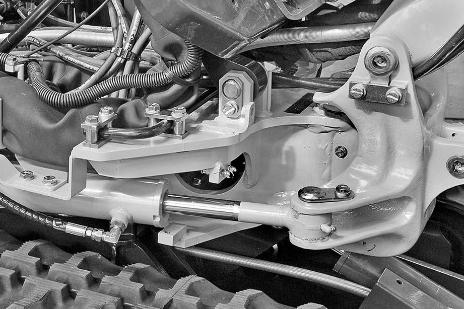
3 -Disconnect the boom swing cylinder (1). (For details, see "BOOM SWING CYLINDER").
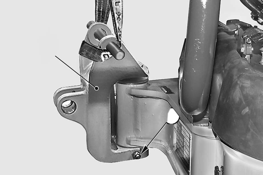
4 -Attach the boom swing support (2) to some hoisting tackle and apply a slight tension to the cable.
5 -Take out the screw (3) and remove the swing support (2).[*1] [*2] a Note down the location of the spacer (5).
4 Boom swing support: approx 20 kg
Installation
•To install, reverse the removal procedure. [*1]
2 Pins: ASL800040 [*2] a Introduce the spacer (5).
2 Supporting surfaces and shims: ASL800040
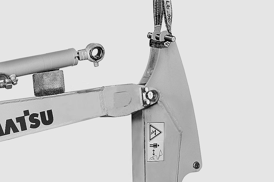
BLADE Removal
1 -Rotate the turret 90º and rest the working equipment on the ground.
2 -Disconnect the cylinder (1) from the blade (2). (For details, see "BLADE CYLINDER").
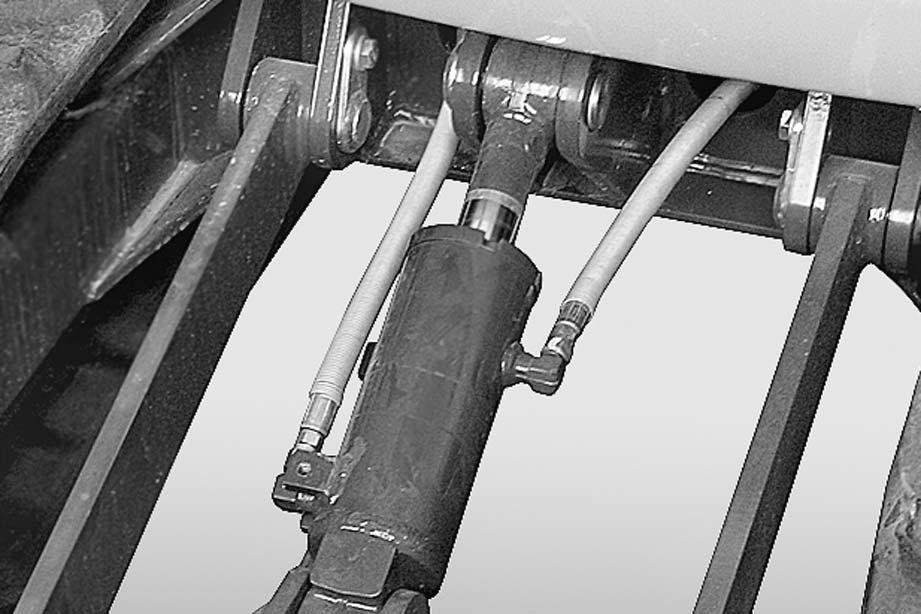
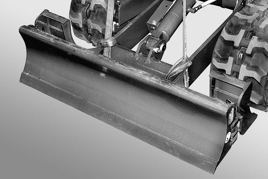
3 -Connect the hoisting tackle to the blade (2) using some cables or the side lift holes (3) and the cylinder connection point (4).
a Adjust the length of the cables to balance the group.
4 -Take out the pin (5).[*1] [*2]
5 -Remove the blade (2).
4 Blade: PC14R-3: approx 50 kg PC16R-3: approx 60 kg
Installation
•To install, reverse the removal procedure.
[*1] a Insert the shims.
[*2] k When aligning the positions between the hole and the pin, turn the engine over at low idling. Do not insert fingers in the holes to check alignment.
MOVING FRAMES (HS version only)
Removal
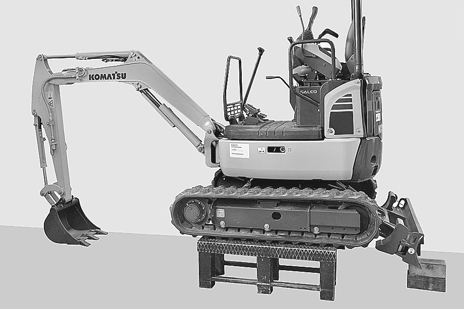
1 -Fully spread the track frame and rotate the revolving frame by 180°.
2 -Raise the blade (1), place it on the ends of blocks “A” and lift the vehicle by forcing down on the blade and working equipment.
3 -Place some stands “B” under the tracks; lower the vehicle so it rests on the stands and stop the engine.
4 -Remove the lower protective panel (2).
5 -Remove the track frame spreading cylinder. (For details, see "TRACK-FRAME SPREADING CYLINDER (HS version only)").
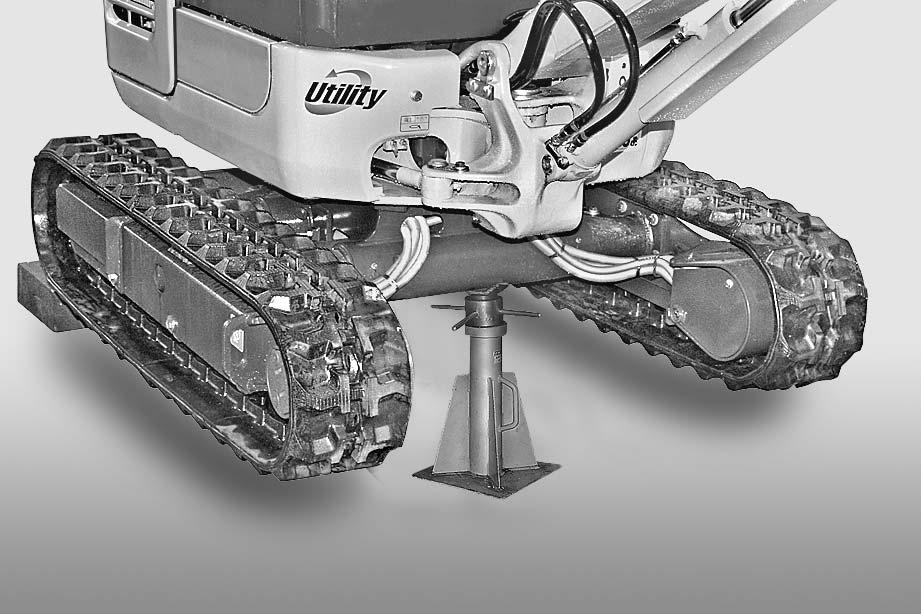
6 -Start the engine, remove stands “B” and place a jack screw “ C ” under the centre of the lower frame on the opposite side of the blade. Lower the vehicle leaving the working equipment resting on the ground.
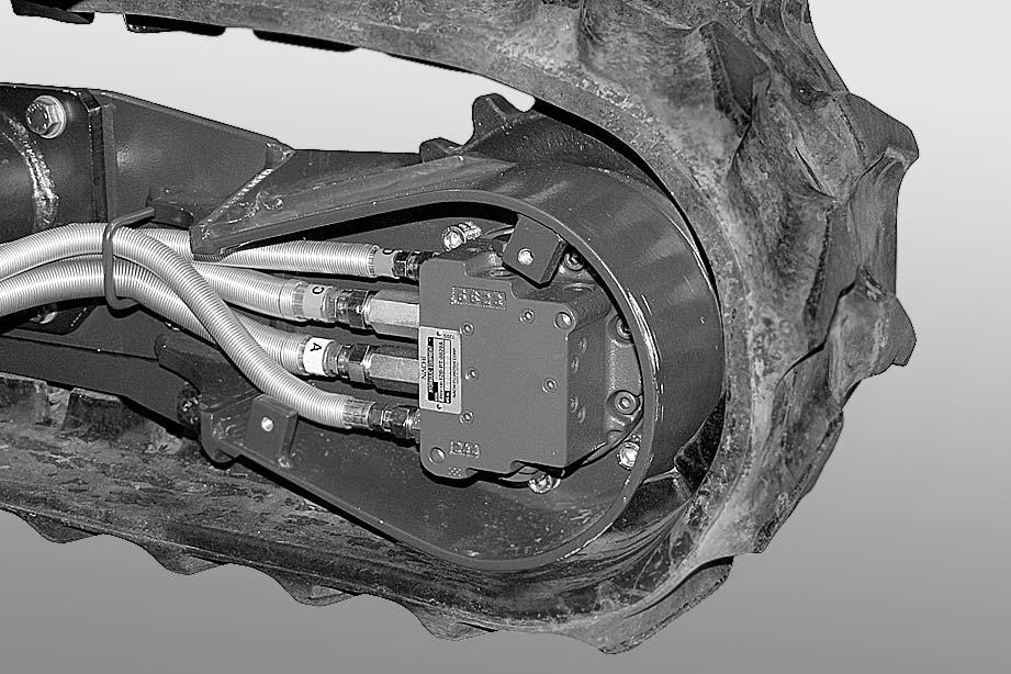
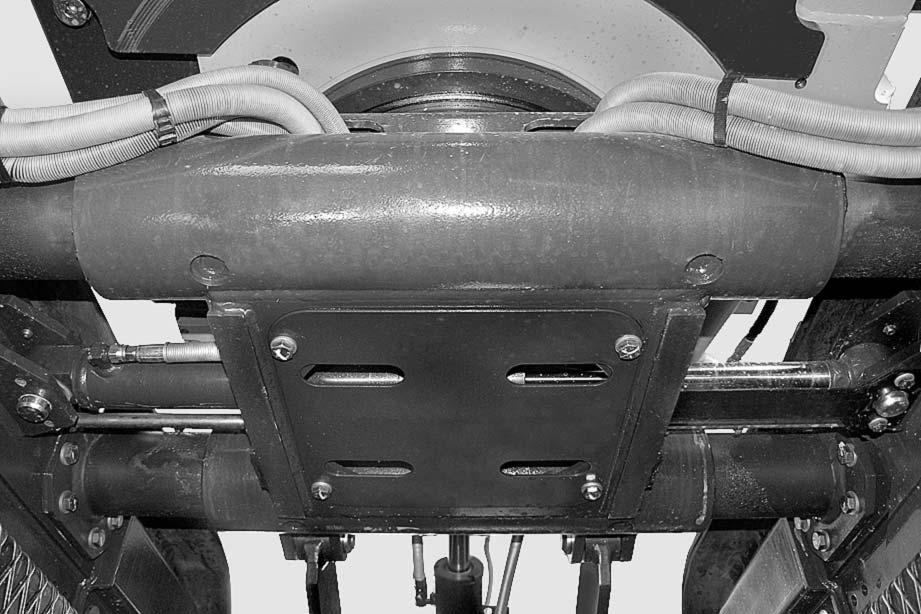
7 -Disconnect hoses (4) from the travel motor and disengage them from the guide (5).
Tightly plug motor hoses and holes.
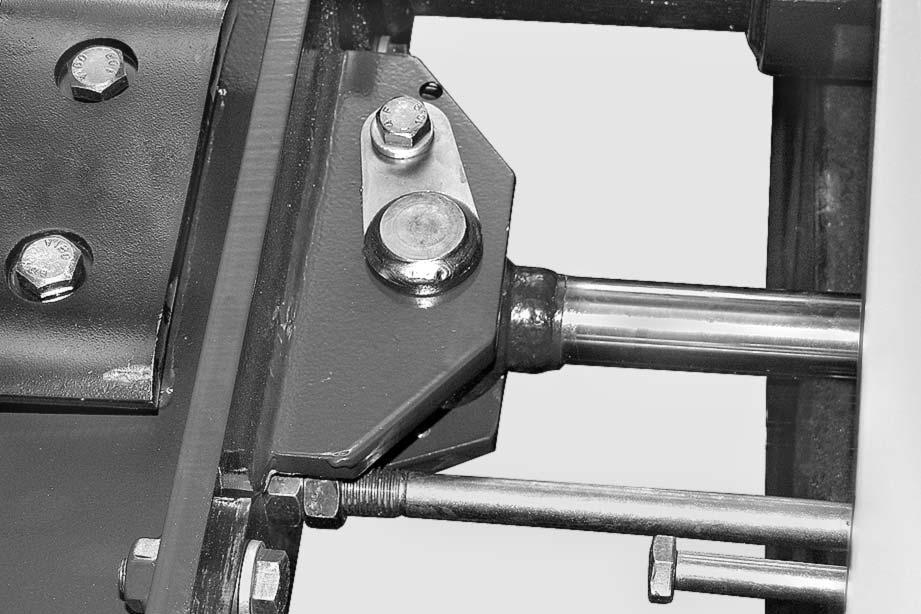
8 -Loosen the locknuts (6) and unscrew the spacer (7) until it is released from the moving frame (8).
9 -Using a fork lift, support the whole moving frame (8) and slide it off.

4 Full moving frame: with rubber track: approx. 105 kg with iron track: approx 138 kg
Installation
•To install, reverse the removal procedure.
1 -Check maximum spreading by measuring the gap “D” between the moving and fixed frames; this can be adjusted with spacer (7). Lock into position with locknuts (6).
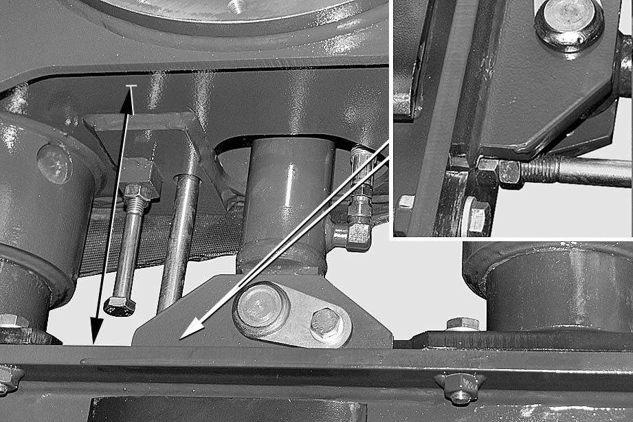
a Size of "D”: 249.5±05 mm
REMOVAL AND INSTALLATION
KOMTRAX STATION (FOR CANOPY)
Removal k Disconnect the negative terminal cable (–) from the battery.
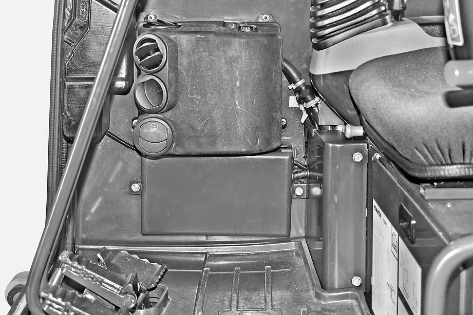
1 -Move the operator's seat completely forward.
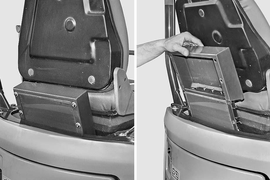
2 -Remove screws (1) and slide the station cover out.
KOMTRAX STATION (FOR CANOPY)
3 -Take out nuts (2) and remove station.
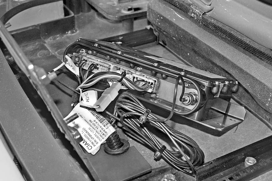
4 -Disconnect connectors (3), (4), (5), and (6).
Installation
•To install, reverse the removal procedure. k Station needs reprogramming every time it is replaced. (See "20 CONTROLS AND ADJUSTMENTS").
30-122
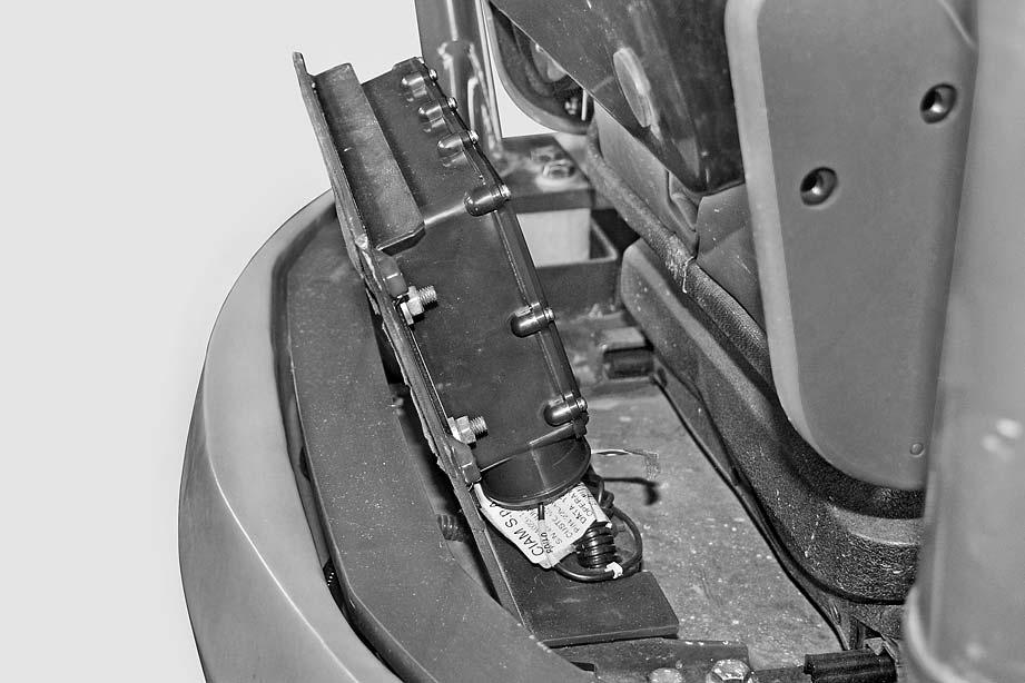
KOMTRAX STATION (FOR CAB)
Removal k Disconnect the negative terminal cable (–) from the battery.
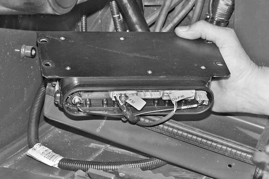
1 -Remove the front guard (1) protecting the RH PPC valve lines.
2 -Remove station cover (2) and disengage the fairleads (3), (4).
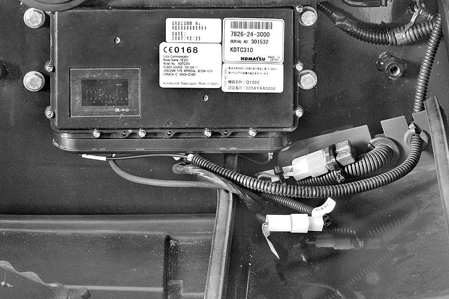
3 -Remove station (5) and disconnect connectors (6), (7), (8), and (9).
Installation k Station needs reprogramming every time it is replaced. (See "20 CONTROLS AND ADJUSTMENTS").
•To install, reverse the removal procedure.