13 minute read
TRAVEL MOTOR (with increment)

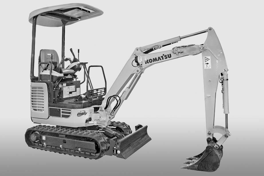
from Komatsu PC14R-3 PC14R-3HS PC16R-3 PC16R-3HS Hydraulic Excavator Shop Manual WEBM007801 PDF DOWNLOAD

Assembling a Only the assembly procedure will be described.
1.
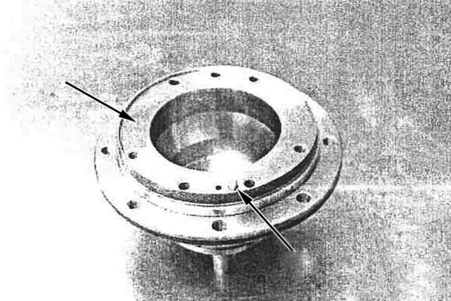
•Body 1 (1) a The parts other than the O-rings are supplied only as the parts of body 1 sub-assembly. a O-ring (5): See the sectional structure drawing. a Plug (6): See photo in 4. a Spool assembly (2) cannot be disassembled.
1 -Insert spool assembly (2), rings (3) (both sides), and springs (4) (both sides) in body 1 (1) in order.
2 -Fit O-rings (5) to plugs (6) (both sides) and tighten the plugs.
3 Plug: 127 – 167 Nm (13 – 17 kgm)
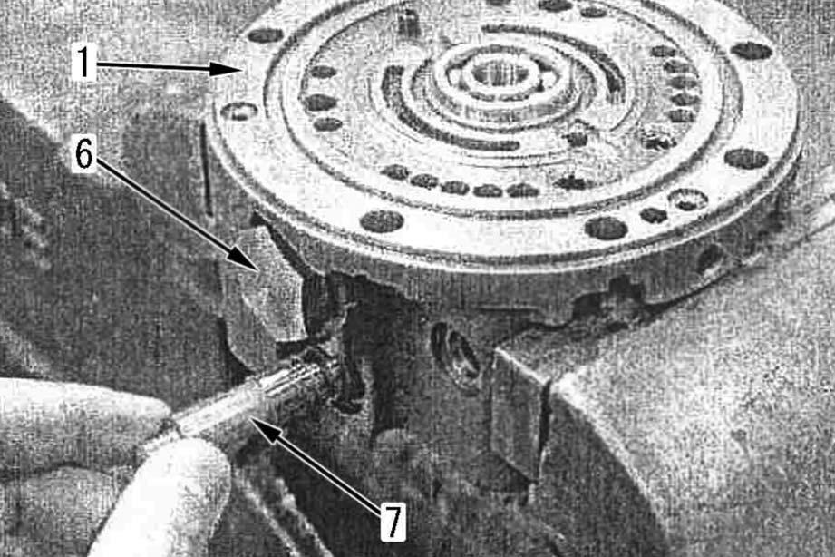
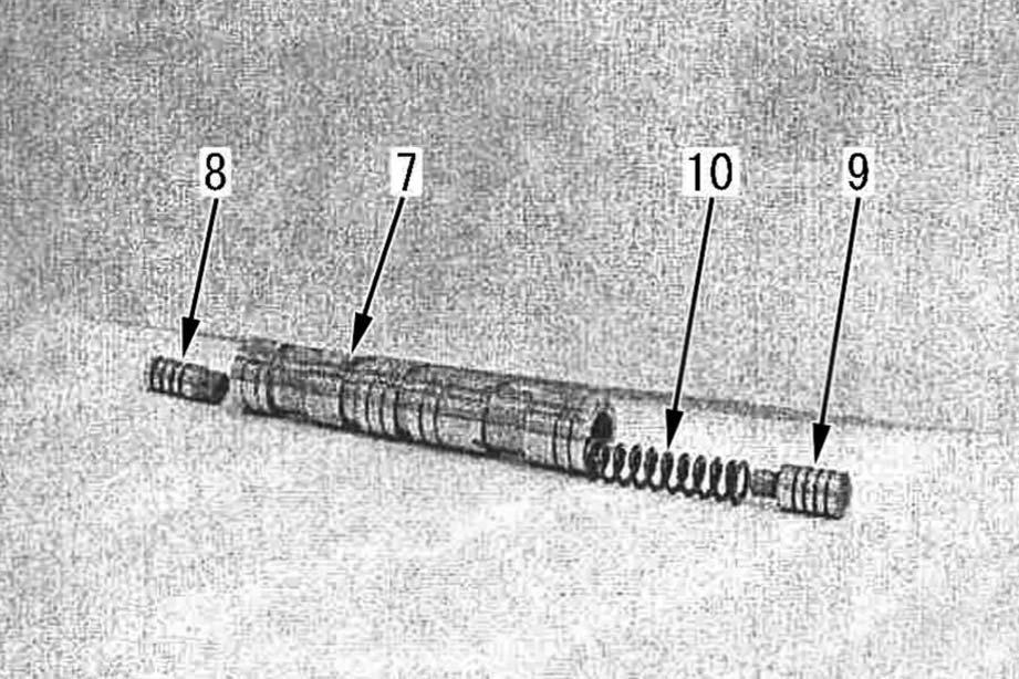
(Width across flats of socket: 27 mm) a Take care of the positions of the spool (7) and spring (10) (See the sectional structure drawing). a O-ring (11): See the sectional structure drawing.
3 -Install spool (8), spool (9), and spring (10) to 2nd gear spool (7).
4 -Insert 2nd gear spool (7) assembly in body 1 (1).
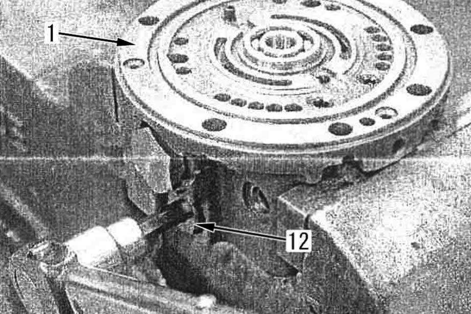
5 -Fit O-rings (11) to plugs (12) (both sides) and tighten the plugs.
3 Plug: 46 – 51 Nm (4.7 – 5.3 kgm)
(Width across flats of hexagon socket head: 8 mm
6 -Insert shaft spool (13) and rollers (14) (both sides) in body 1 (1) and tighten plugs (15) (both sides).
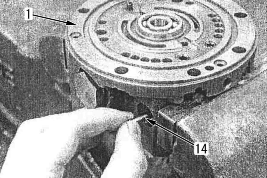
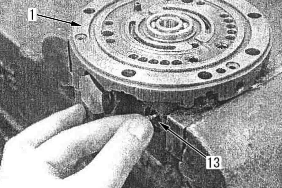
3 Plug: 12 – 18 Nm (1.2 – 1.8 Nm)
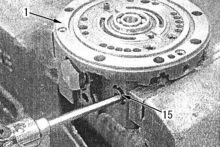
(Width across flats of hexagon socket head: 5 mm
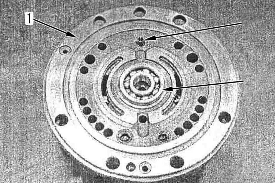
7 -Press fit bearing (17) and spring pin (16) to body 1 (1).
8 -Install O-rings (18) and (19) to body 1.
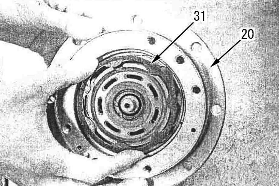
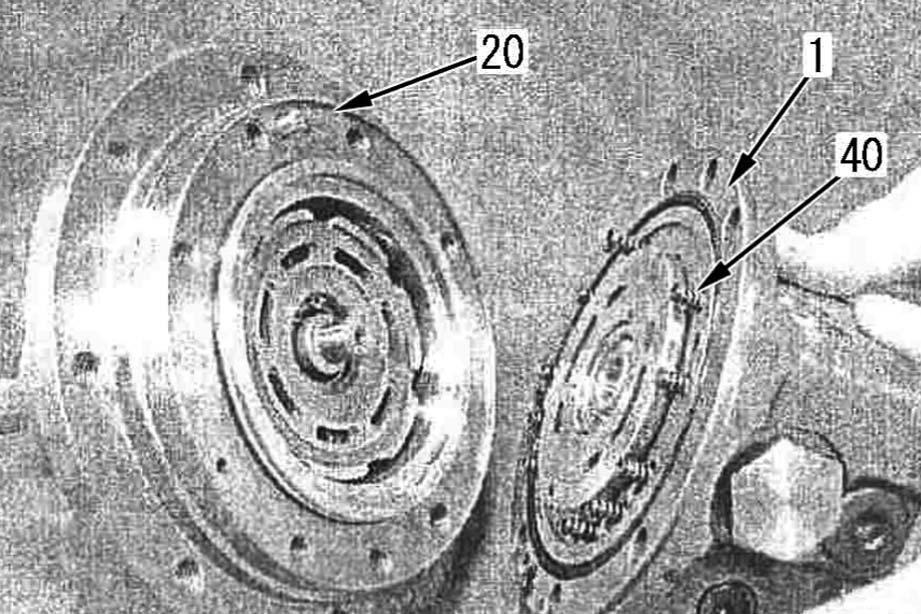
Body 2 (20)
9 -Press fit oil seal (21) to body 2 (20)
2 Sealing ring lips: ASL800050 a The shaft is not supplied loose. a Take care not to damage oil seal (21) with the shaft.
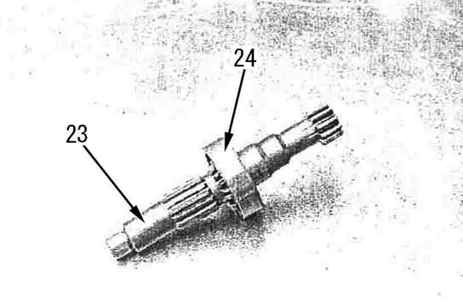
10 -Install parallel pin.
11 -Press fit bearing (24) to shaft (23).
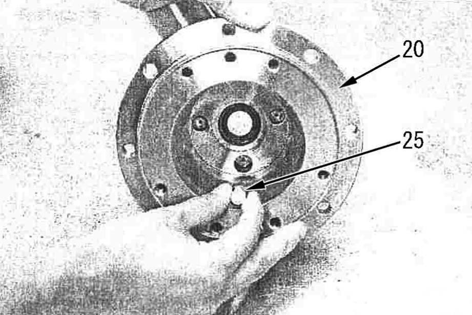
12 -Install control piston (25) to body 2 (20)..
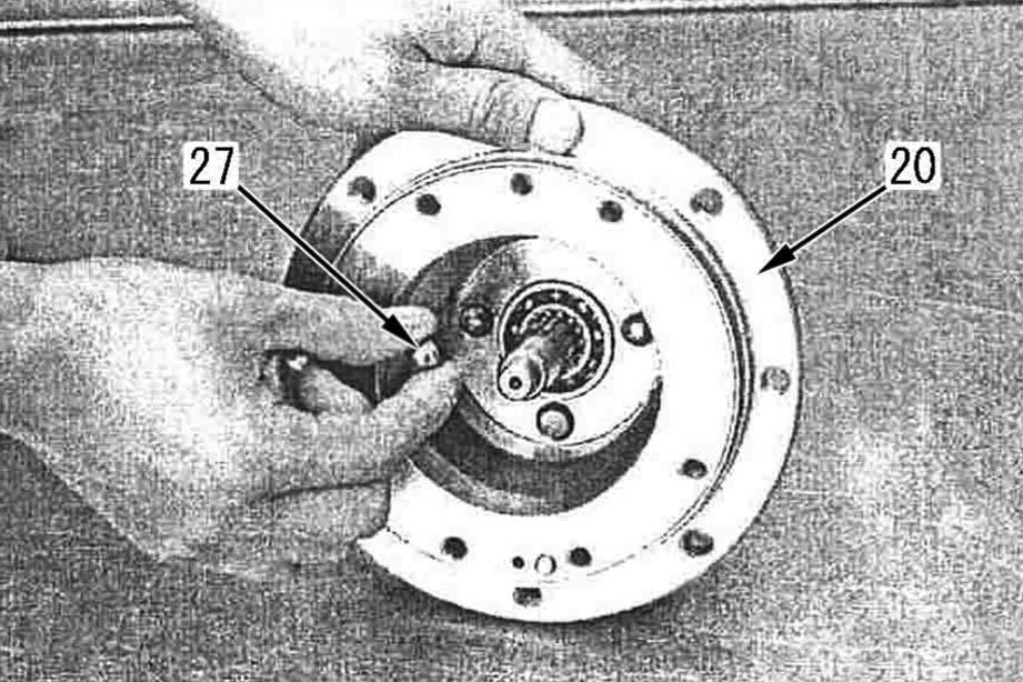
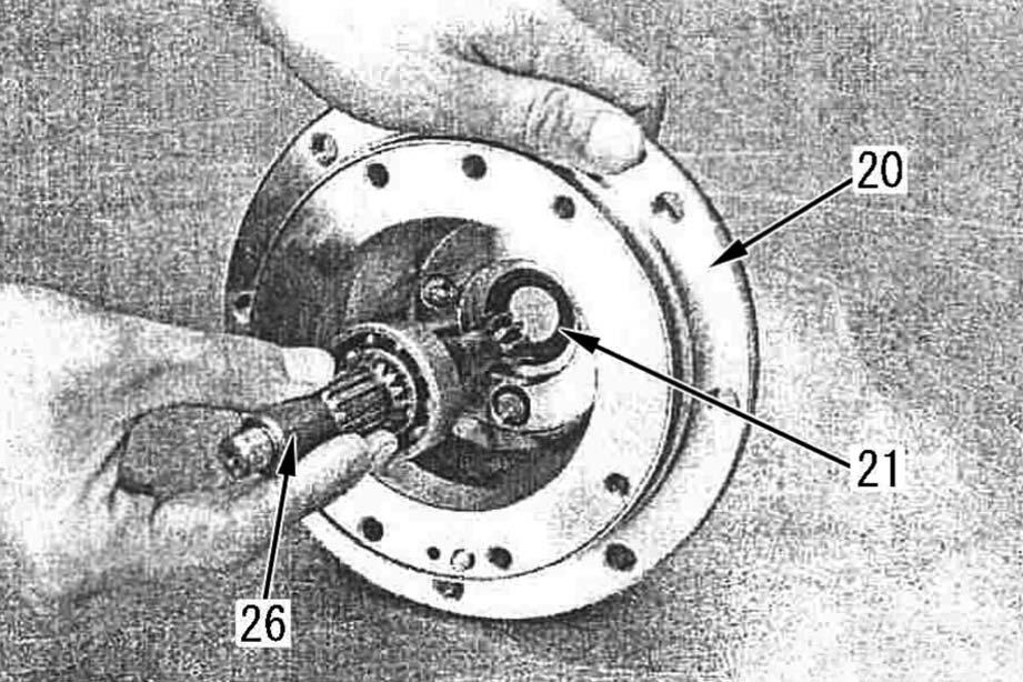
13 -Install shaft assembly (23) to body 2 (20).
14 -Install balls (27) (2 pieces) to body 2 (20)
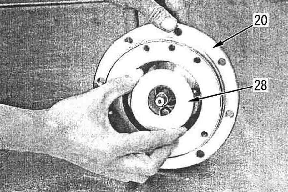
15 -Install the swash plate (28).
2 Sliding surface of swash plate: Hydraulic oil
2 Rear side of swash plate: ASL800050 (only if swash plate separates)
16 –Install cylinder barrel (30) into body 2 (20) so that the shoes (29) contact the swash plate (28) a Take care of the positional relationship between the O-rings and backup rings.
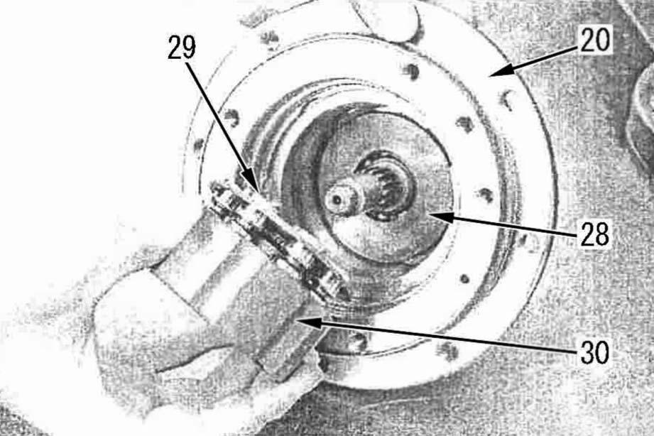
2 Piston holes on cylinder barrel: hydraulic oil a The parts of cylinder barrel assembly (30) are supplied only in an assembly.
17 -Set disc plate (31) in body 2 (20), matching it to the groove.
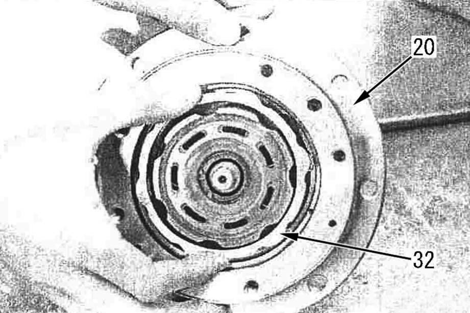
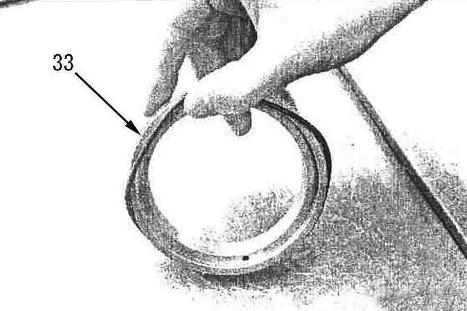
19 -Fit O-rings (34) and (35) and backup rings (36) and (37) to brake piston (33) to make up brake piston assembly (38).
20 -Insert brake piston assembly (38) in body 2 (20).
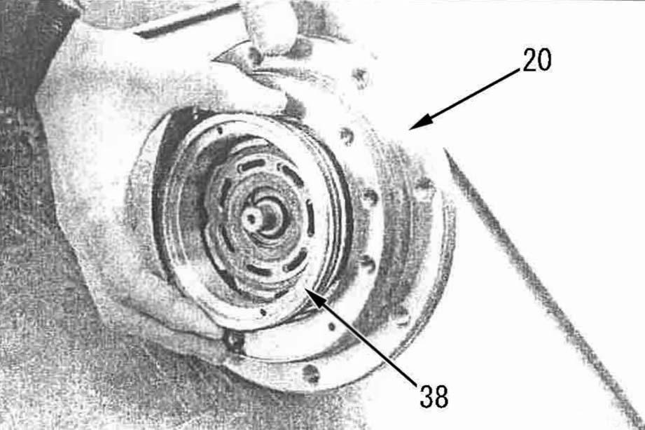
2 O-ring: ASL800050 a When assembling, take care that the seals will not be caught.
5 Inside of body 2 (20): Hydraulic oil (approx.100 cm3) a Install the valve plate with the copper side up (on the cylinder barrel side).
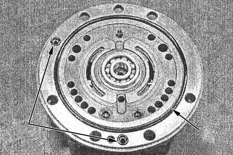
21 -Install valve plate (39) and springs (40) (14 pieces) to body 1 (1) and combine them with body 2 (20).
2 Sliding surface (Copper side) of valve plate: hydraulic oil
2 Back side (Steel side) of valve plate: ASL800050 a Install springs (40) (14 pieces) to the places marked with q in the following figure
2.
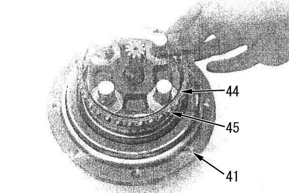
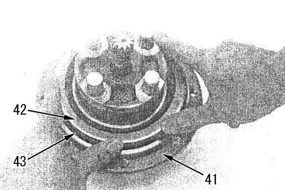
1 -Install floating seal (42) and O-ring (43) to hydraulic motor (41).
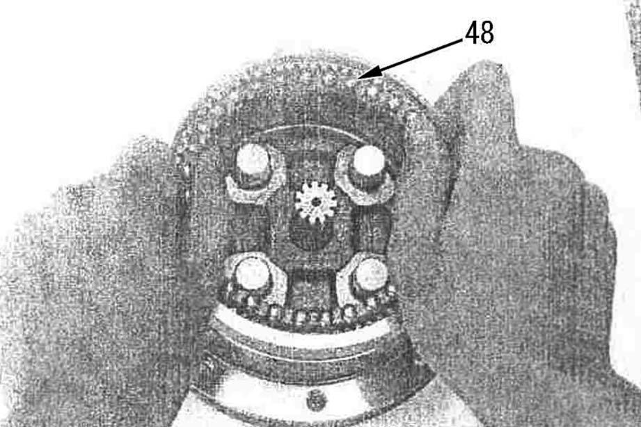
2 O-ring: ASL800050 a Insert seal ring (42) with the sealing surface up. a Take care of the directions of the bearing inner (44) race and retainer (45). (See the sectional structure drawing.) a The steel balls may come off the retainer. Take care not to lose them
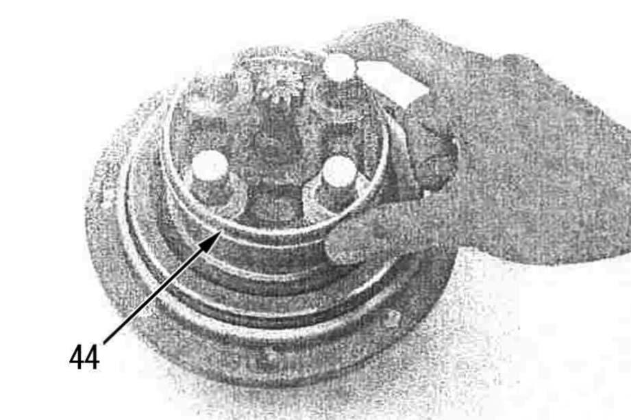
2 -Install bearing inner race (44) and steel balls (45) having the retainer to hydraulic motor (41) in order.
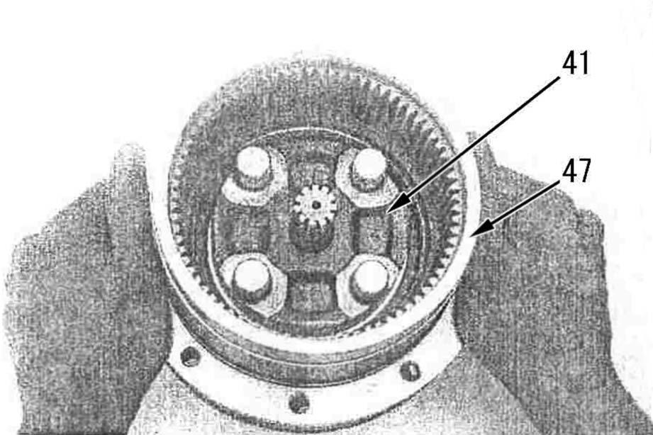
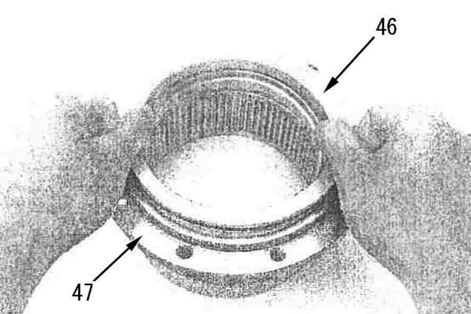
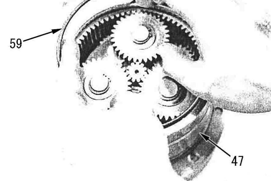
3 -Set the O-ring to seal ring (46) and install them to body (47).
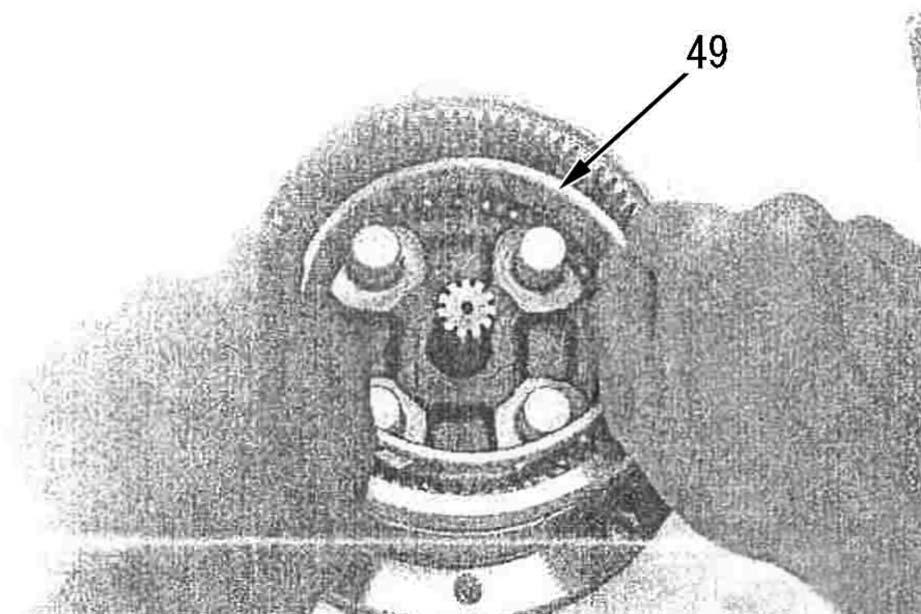
2 O-ring: ASL800050 a Insert seal ring (46) with the sealing surface up. a Use a press or other suitable implement to install the body (47). a Take care of the directions of the bearing inner (49) race and retainer (48). (See the sectional structure drawing.) a The steel balls may come off the retainer. Take care not to lose them a Adjust the preload on the bearing by the thickness of the snap ring. a Install these parts to all of the 4 places. a Install the thrust plate with the convex side up. a The snap ring has different sides. Install it with the edge part up (on the cover side). a If the snap ring is expanded too much, its clamping force is lost. If it does not have sufficient clamping force, replace it a Sun gear (57): See the sectional structure drawing. a Sun gear and carrier 2 assembly (58) is supplied only as an assembly. (Including sun gear (57).
4 -Install body (47) to hydraulic motor (41).
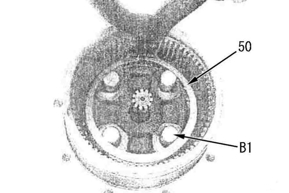
5 -Install steel balls (48) having the retainer and bearing inner race (49) to the hydraulic motor in order.
6 -Fix the bearing with snap ring (50).
7 -Install ring (51), thrust washer (52), gear (53), and needle (54) to B1 pin of the hydraulic motor.
8 -Install thrust plate (55) and fix it with snap ring (56).
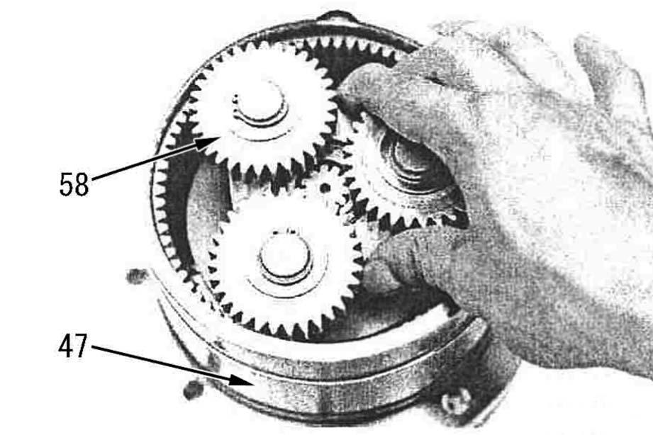
9 -Install sun gear and carrier 2 assembly (58) to body (47).
10 -Install O-ring (59) to body (47).
2 O-ring: ASL800050
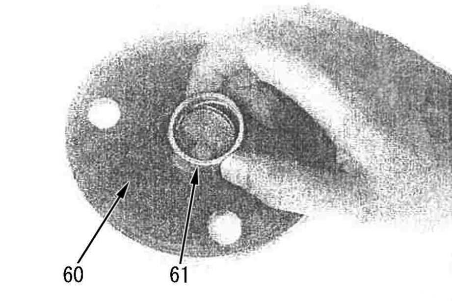
11 -Insert slide ring (61) in cover (60).
2 Slide ring: ASL800050 For fitting the slide ring to the cover
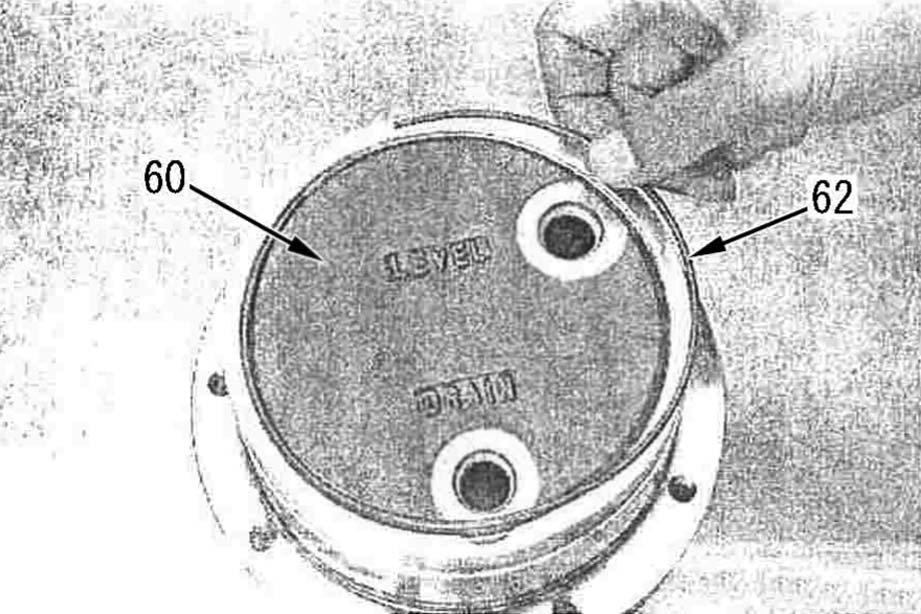
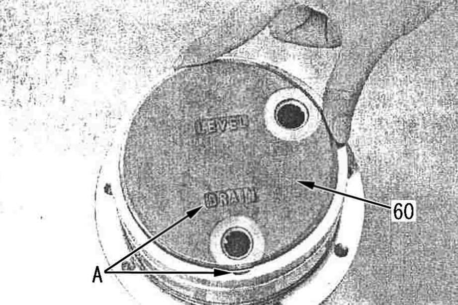
12 -Supply hydraulic oil and install cover (60).
5
Body (47) : Hydraulic oil (approx.300 cm3) a Take care not to damage the O-ring. a Match the letters of "DRAIN" on the cover to the cut of the body. (A) a Use a flat bladed screwdriver on the edge of the snap ring to drive in the ring following the contour of the body (47). a Tighten the plug on the side of the letters of "DRAIN" first. (Lock the cover with the flange of the plug.)
13 -Install O-snap ring (62) to fix cover (60).
14 -Tighten socket head plugs (63) (G3/8).
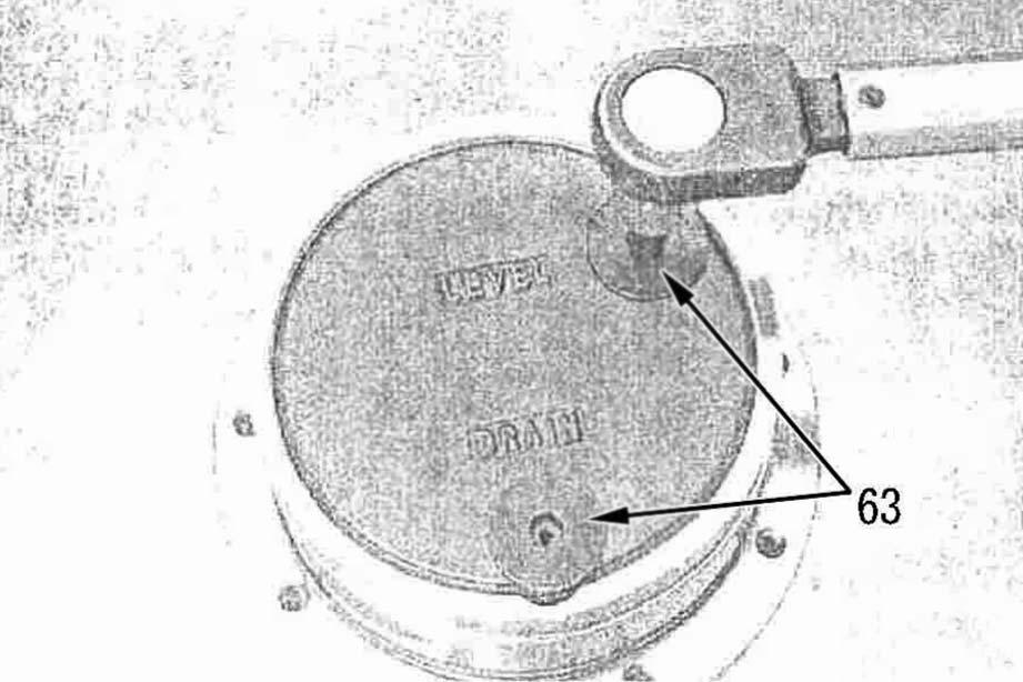
2 Plug: 46 – 51 Nm {4.7 – 5.2 kgm}
(Width across flats of hexagon socket head: 8 mm)
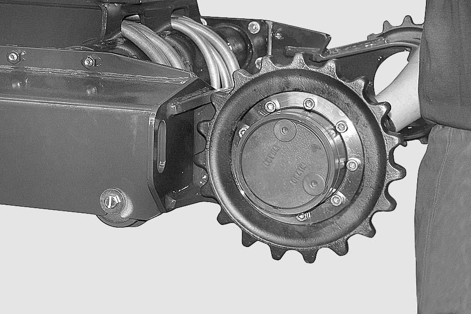
Sprocket Wheel
Removal
1 -Remove the track pertaining to the wheel to be removed. (For details, see "TRACKS").
2 -Place a safety block "A" underneath the track-frame.
3 -Take out the screws (1) and their washers.
4 -Remove the sprocket wheel (2).[*1]
4 Sprocket wheel: 5 kg
Installation
•To install, reverse the removal procedure. [*1]
2 Screws: Loctite 262
3 Screws: 75 Nm
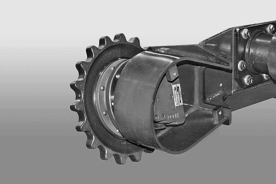
Complete Final Drive
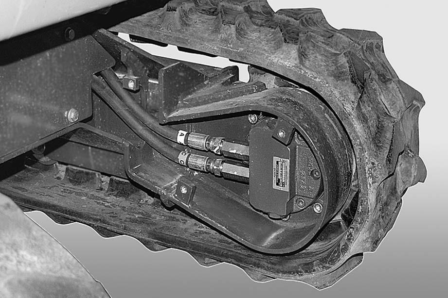
Removal
1 -Remove the track relating to the final drive concerned. (For details, see "TRACKS").
2 -Disconnect the tubes (1) from the travel motor (2). (For details, see "TRAVEL MOTOR").
3 -Take out the screws (3).
4 -Remove the final drive (4) and the drive wheel (5).
4 Complete final drive: approx 17 kg
Installation
•To install, reverse the removal procedure.
2 Final drive screws: Loctite 262
3 Final drive screws: 75 Nm
1 -Start the engine and bleed air from the travel motors. (For details, see "20 CONTROLS AND ADJUSTMENTS").
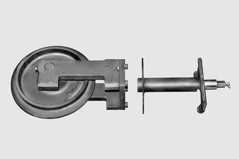
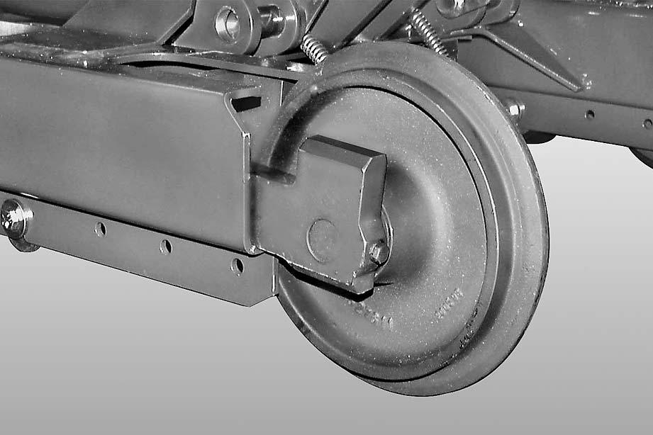
IDLER WHEEL - RECOIL SPRING
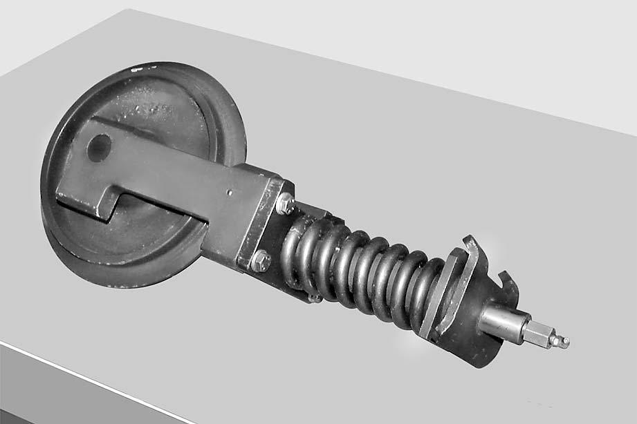
Removal
1 -Remove the track. (For details, see "TRACKS").
2 - Rubber shoe specification: Slide off the idler wheel (2) and cylinder (3) from the lower frame (1). For steel tracks: slide off the idler wheel (2) and recoil spring (4).
Installation
•To install, reverse the removal procedure.
1 -Restore track tension.
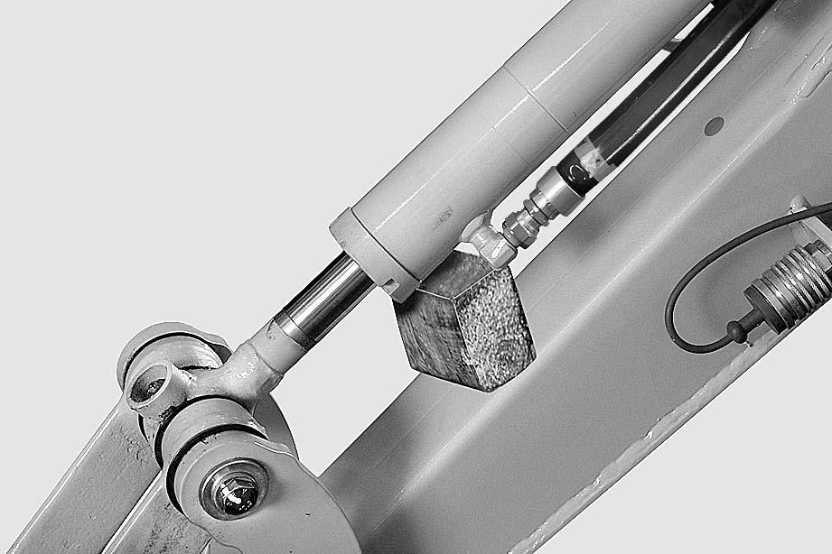
Boom Cylinder
Removal
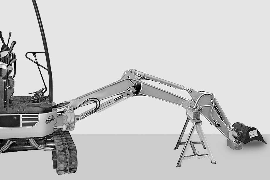
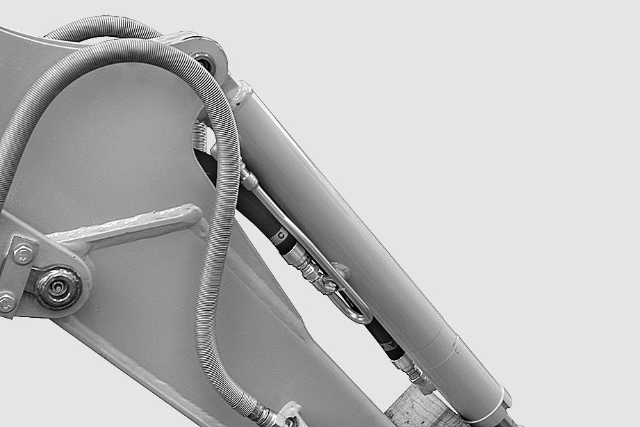
k Fully extend the arm and open the bucket completely. Lower the equipment until it rests on the ground.
1 -Remove the protection (1) and the relative sliding shoes.[*1] a Note down position of any shims and direction of assembly.
2 -Stop the engine, release the pressures in the cylinder by moving the right-hand PPC valve lever several times.
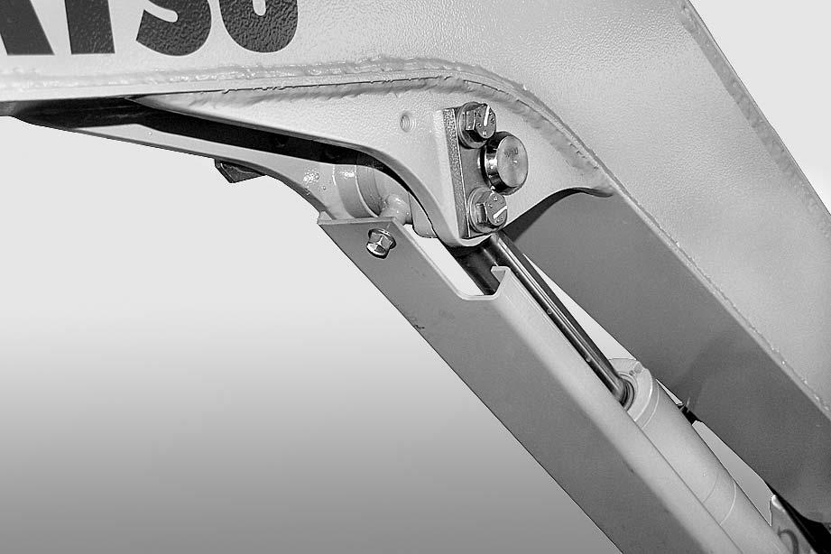
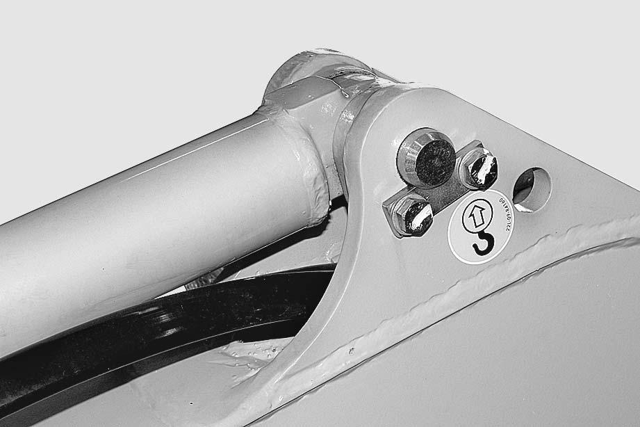
3 -Remove the pin (2).[*2] [*3]
4 -Lower the cylinder (3) until it rests on a stand “A”.
5 -Start the engine to retract the piston.
6 -Stop the engine and release the residual hydraulic pressures. (For details, see "20 CONTROLS AND ADJUSTMENTS").
7 -Disconnect the tubes (5) and plug them. Also plug the holes in the cylinder to prevent the entry of impurities.
8 -Remove the pin (6).[*2][*3][*4] a Note down position of any shims and direction of assembly.
9 -Remove the cylinder (3).
Installation
•To install, reverse the removal procedure.
[*1] a Check the centering and the smooth movement of the protection (1) on the shoes.
2 Shoes and guides: ASL800050
[*2]
[*3] a Insert the shims. kWhen aligning the positions between the hole and the pin, turn the engine over at low idling. Do not insert fingers in the holes to check alignment.
[*4]
2 Internal bushings: ASL800050 a After bleeding the air, check the oil level in the tank.
1 -Start the engine and bleed the air from the cylinder. (For details, see "20 CONTROLS AND ADJUSTMENTS").
Arm Cylinder
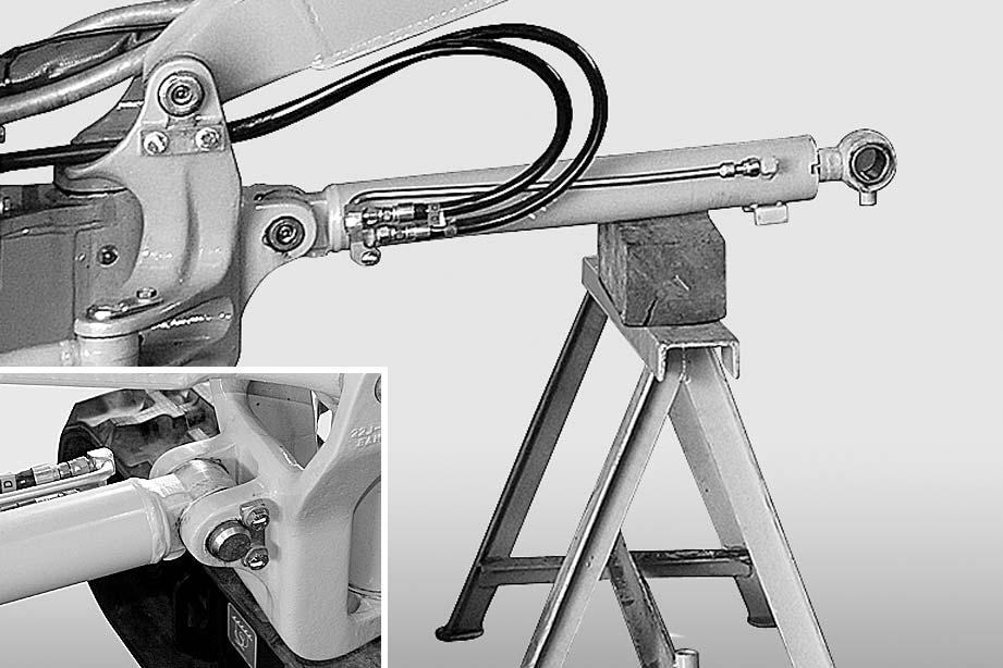
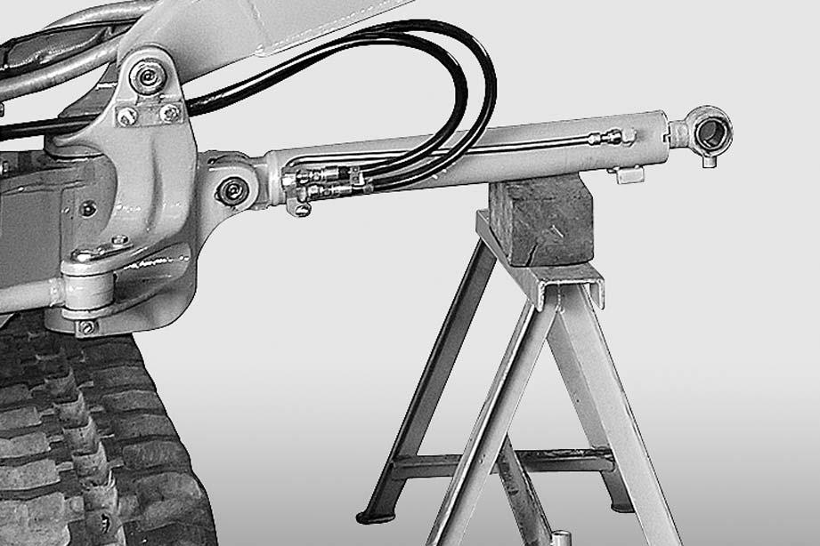
Removal k Fully open the front working equipment. Operate and lay the boom on a stand “A” and the arm on a block “B”.
1 -Stop the engine and release the pressures from the cylinder by moving the left-hand PPC valve lever several times.
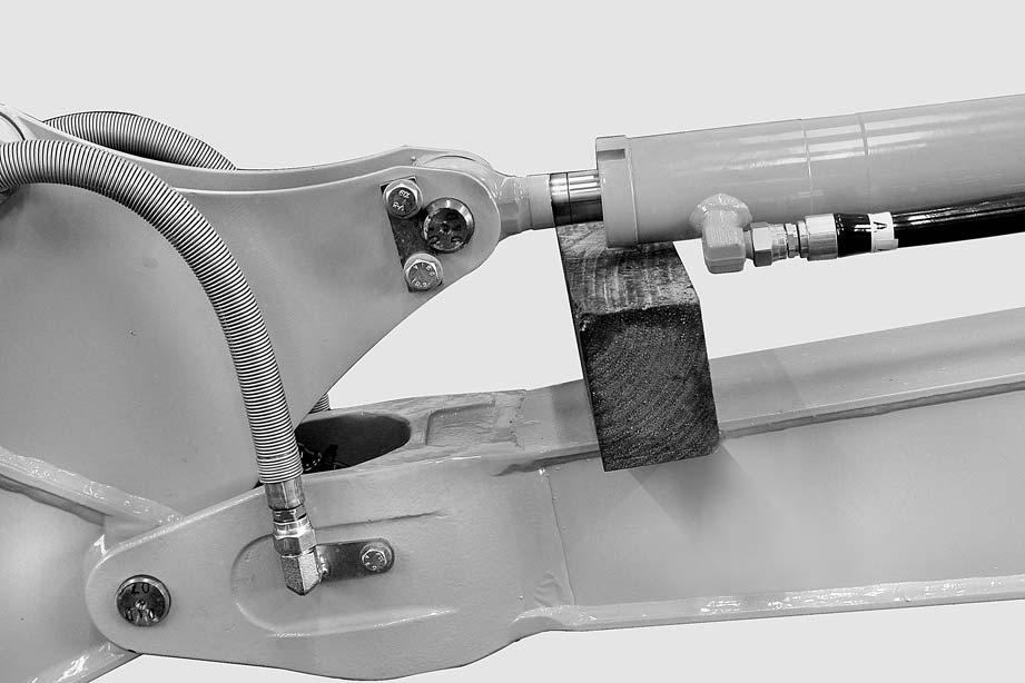
2 -Place a block "C" beneath the cylinder (1).
3 -Remove the pin (2).[*1] a Note down position of any shims and direction of assembly. a Note down position of any shims and direction of assembly.
4 -Start the engine to retract the piston (3).
5 -Stop the engine and release the residual hydraulic pressures. (For details, see "20 CONTROLS AND ADJUSTMENTS").
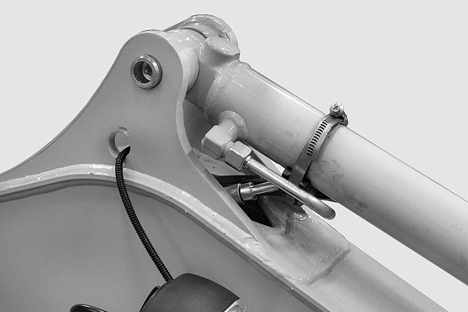
6 -Remove hose clamp (4).
7 -Disconnect the tubes (5) and plug them. Also plug the holes in the cylinder to prevent the entry of impurities.
8 -Remove the pin (6).
9 -Remove the cylinder (1).[*1]
Installation
•To install, reverse the removal procedure. [*1]
2 Internal bushings: ASL800040 a Insert the shims.
2 When aligning the positions between the hole and the pin, do not insert fingers in the holes to check alignment.
1 -Start the engine and bleed the air from the cylinder. (For details, see "20 CONTROLS AND ADJUSTMENTS").
After bleeding the air, check the oil level in the tank.
Bucket Cylinder
Removal
k Fully open the front working equipment. Operate and lay the boom on a stand “A” and the arm on a block “B”.
1 -Stop the engine, release the pressures in the cylinder by moving the right-hand PPC valve lever several times.
2 -Place a block “C” beneath the cylinder (1) and remove the pin (2).[*1] [*2]
3 -Start the engine and retract the piston rod (4) and collect the shims (3).[*3]
4 -Stop the engine and release the residual hydraulic pressures. (For details, see "20 CONTROLS AND ADJUSTMENTS").
5 -Disconnect the tubes (5) and (6) and plug them. Also plug the holes in the cylinders to prevent the entry of impurities.

6 -Remove the pin (9).[*2] [*3] [*4]
7 -Remove cylinder (1) and shims (10).
Installation
•To install, reverse the removal procedure.
[*1]
2 Internal bushings: ASL800040 a Insert the shims. kAfter bleeding the air, check the oil level in the tank.
2 When aligning the positions between the hole and the pin, do not insert fingers in the holes to check alignment.
1 -Start the engine and bleed the air from the cylinder. (For details, see "20 CONTROLS AND ADJUSTMENTS").
BOOM SWING CYLINDER Removal
kLower the working equipment to the ground with all safety devices engaged. Rest the back of the bucket on the ground with the arm in a vertical position.
1 -Stop the engine and move the command pedal several times to release residual pressures.
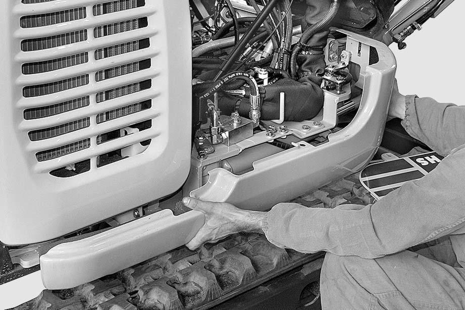
2 -Tilt the floor (1) and remove the right side door and guard (2).
3 -Apply a support to the cylinder (3).
4 -Remove the pin (4) and disengage the piston rod from its support (5).[*1] [*2] a Note down position of any shims and direction of assembly.
5 -Start the engine and retract the piston rod (6).
6 -Stop the engine and release the residual hydraulic pressures. (For details, see "20 CONTROLS AND ADJUSTMENTS").
7 -Disconnect the hoses (7) and plug them; also plug the holes in the cylinder (3) to prevent the entry of impurities.
8 -Remove the pin (7) on the base side and remove the cylinder.
[*1] [*2] [*3] a Note down position of any shims and direction of assembly.
Installation
•To install, reverse the removal procedure.
[*1] a Insert the shims. kWhen aligning the positions between the hole and the pin, do not insert fingers in the holes to check alignment.
[*2]
2 Internal bushings: ASL800040 a After bleeding the air, check the oil level in the tank.
1 -Start the engine and bleed the air from the cylinder. (For details, see "20 CONTROLS AND ADJUSTMENTS").
Blade Cylinder
Removal k Lower the working equipment to the ground with all safety devices engaged. Rest the back of the bucket on the ground with the arm in a vertical position. a Place a supporting block «A» beneath the cylinder “A”.
1 -Remove the protection (1).
2 -Stop the engine, release the pressures in the cylinder (2) by moving the command lever several times in both directions.
3 -Remove the pin (3).[*1] [*3] a Note down position of any shims and direction of assembly.
4 -Start the engine to retract the piston (4).[*2]
5 -Stop the engine and release the residual hydraulic pressures. (For details, see "20 CONTROLS AND ADJUSTMENTS").
6 -Disconnect the tubes (5) and plug them. Also plug the holes in the cylinder (2) to prevent entry of impurities.
7 -Remove the pin (6).[*1] [*2] [*3]
8 -Remove the cylinder (2).
Installation
•To install, reverse the removal procedure.
[*1]
[*2] a Insert the shims. k When aligning the positions between the hole and the pin, do not insert fingers in the holes to check alignment.
[*3]
2 Internal bushings: ASL800040 a After bleeding the air, check the oil level in the tank.
1 -Start the engine and bleed the air from the cylinder. (For details, see "20 CONTROLS AND ADJUSTMENTS").
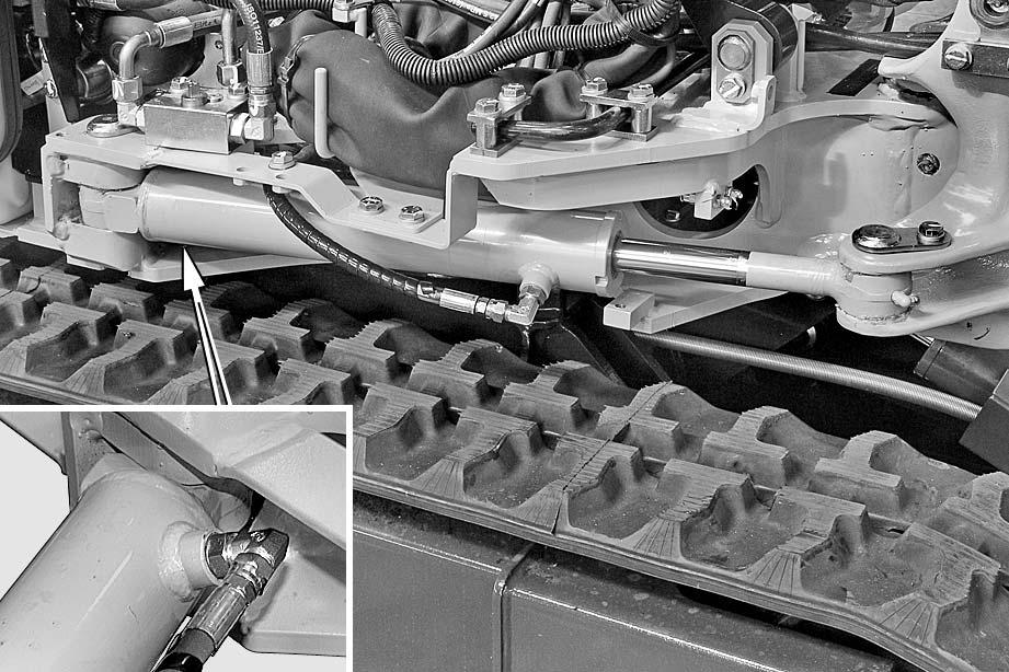
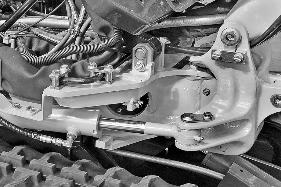
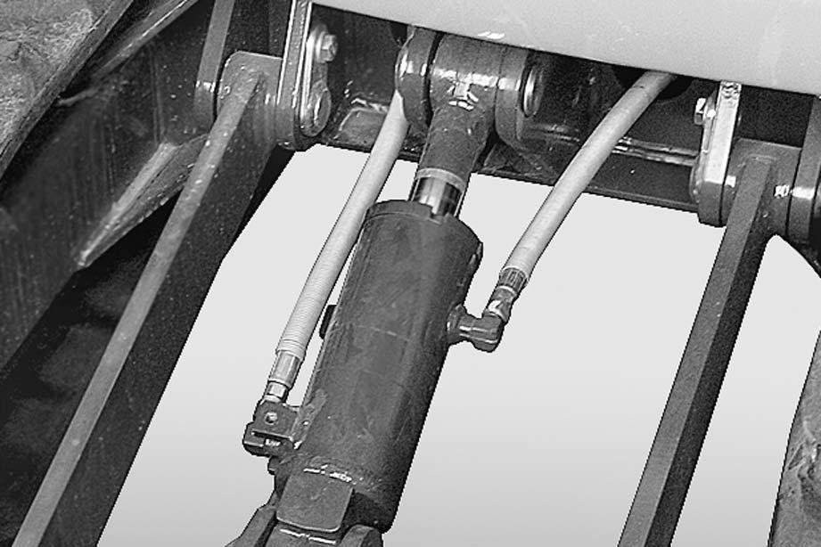
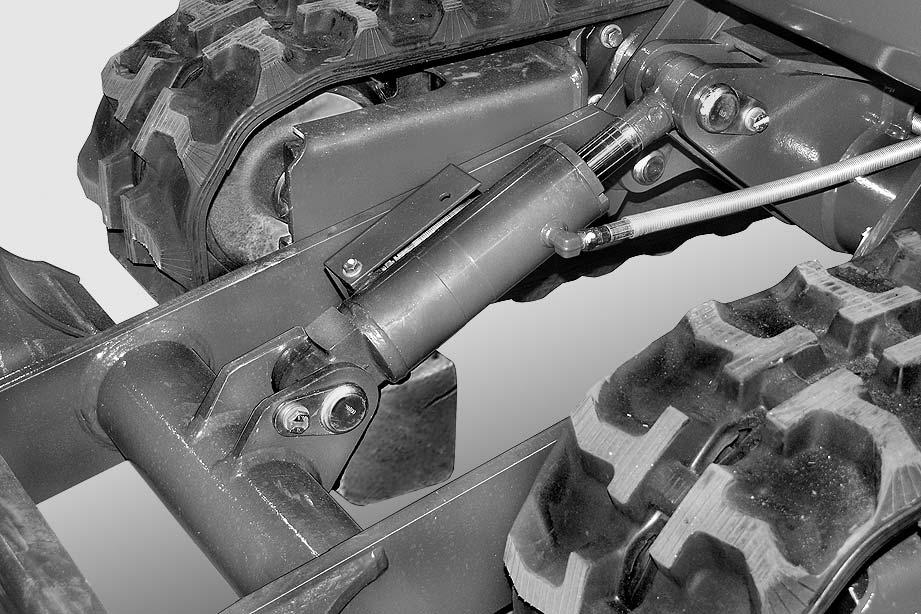
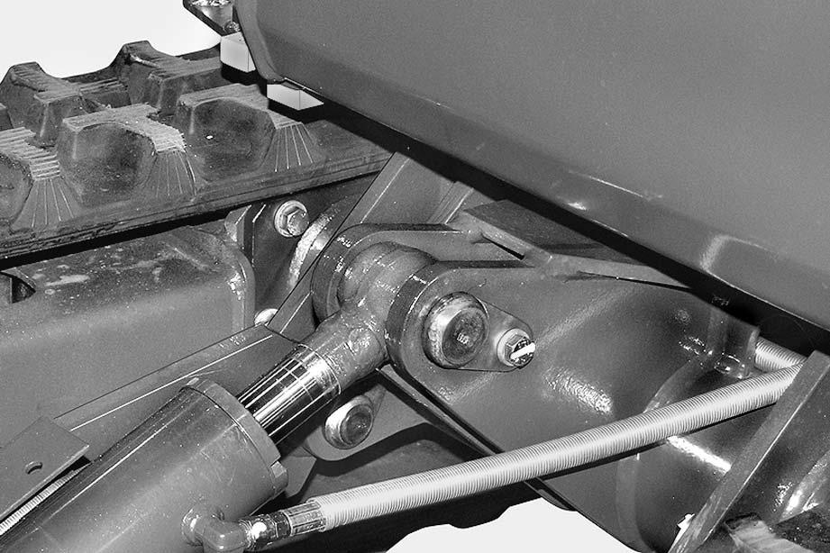
TRACK-FRAME SPREADING CYLINDER (HS version only)
Removal
1 -Spread the lower track-frame all the way and select the “blade” operating mode; rotate the revolving frame by 180°.
2 -Raise the blade (1), place blocks “A” under it, and raise the vehicle by forcing down on the blade and working equipment (2).
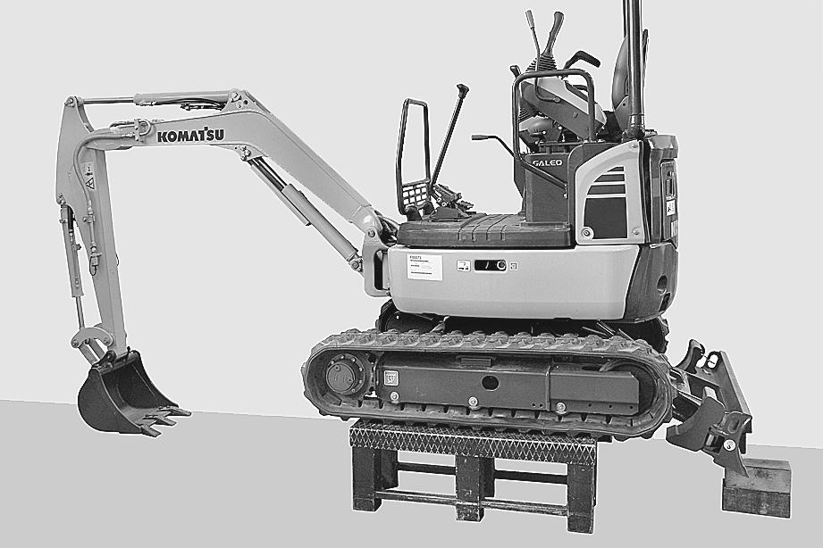
3 -Place some stands “B” under the tracks; lower the vehicle so it rests on the stands and stop the engine.
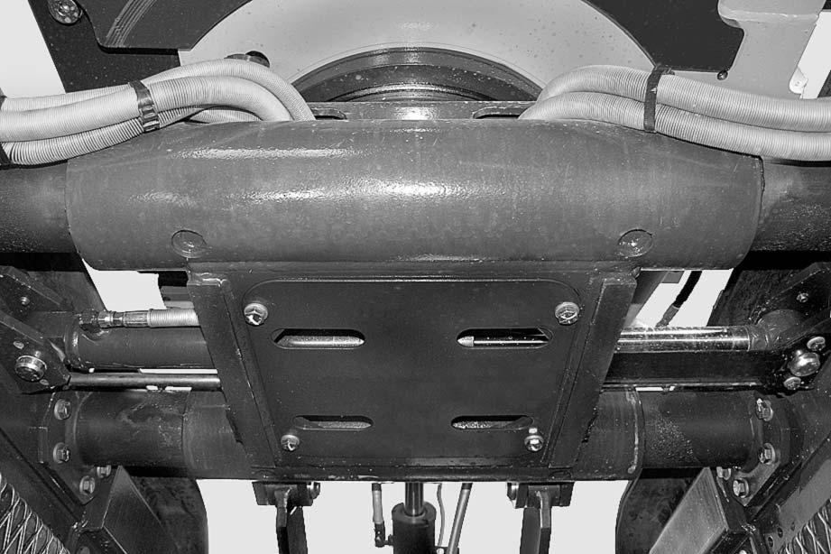
4 -Remove the lower protective panel (2) and the piston rod guard (3).
5 -Support the cylinder (4) with a belt.
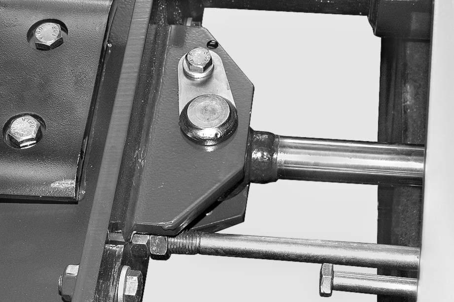
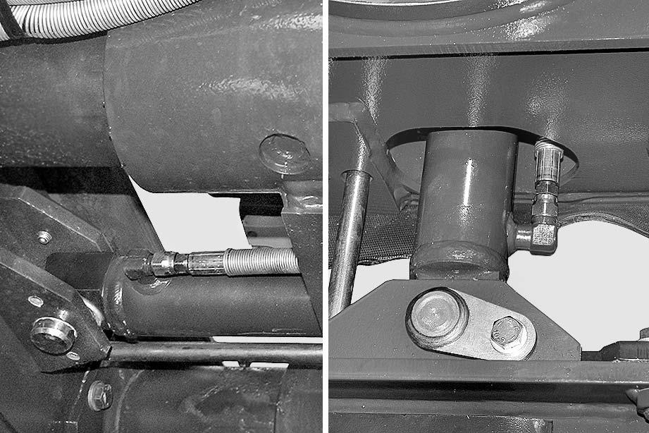
6 -Remove the screw (5) and remove the piston connection pin (6), (7)[*1] [*2]
7 -Start the engine to retract the piston (7).
8 -Stop the engine and release the residual pressures.
9 -Disconnect hoses (8), (9) from cylinder. a Plug lines and holes to prevent contamination.
10 -Remove the screw (10), pin (11) and cylinder (4). [*1] [*2]
Installation
•To install, reverse the removal procedure.
[*1] kWhen aligning the positions between the hole and the pin, turn the engine over at low idling. Do not insert fingers in the holes to check alignment.
[*2]
2 Internal bushings: ASL800040 a After bleeding the air, check the oil level in the tank.
1 -Start the engine and bleed the air from the cylinder. (For details, see "20 CONTROLS AND ADJUSTMENTS").
Hydraulic Cylinders
Assembling a The following steps are common to all the cylinders, unless otherwise specified. To disassemble, reverse the assembly procedure. a Take care not to damage the packings, dust seals, Orings, etc. a Clean all the parts. After assembling, cover the piping ports and pin holes to prevent dirt from entering them. a Do not insert each backup ring forcibly, but warm it in water at 50 – 60 °C and then insert it.
Cylinder
1 -Press fit bushing (24).
2 -Press fit 2 dust seals (23).
Piston Rod
1 -Press fit bushing (22) to piston rod (6).
2 -Press fit 2 dust seals (21)
Cylinder Head Assembly
1 -Using tool U4, press fit bushing (20) to cylinder head.
a Do not perform this step for boom cylinder.
2 -Using tool U5, press fit dust seal (18).
3 -Install snap ring (17).
4 -Install rod packing (19).
5 -Install O-ring (15) and backup ring (16).
6 -Install O-ring (30).
7 -Install O-ring (12) and 2 backup rings (13).
a Install O-ring (12) and 2 anti-extrusion rings (13).
a Boom cylinder:
8 -Install cylinder head assembly (11) to piston rod (6).
Piston Assembly
1 -Install cushion plunger (10) to piston rod (6). a Perform this step for only the boom cylinder
2 -Set piston ring (9) to tool U6 and give 8 – 10 turns to the handle to expand the piston ring.
3 -Install piston ring (9) to piston (8).
4 -Using tool U7, contract piston ring (9).
5 -Install wear ring (7).
Removal And Installation
6 -Install piston assembly (5) to piston rod (6)
7 -Set piston rod assembly (6) to tool U1.
8 -Using tool U3, install piston nut (4).
•Width across flats of socket:
Boom cylinder:
PC14R-3: 30 mm - PC16R-3: 36 mm
Arm cylinder:
PC14R-3: 32 mm - PC16R-3: 41 mm
Bucket cylinder: 32 mm
Boom swing cylinder: 32 mm
Blade cylinder:
PC14R-3: 36 mm - PC16R-3: 41 mm
Variable gauge cylinder:
2 Nut: Loctite 262
3 Nut:
Boom cylinder:
PC14R-3: 245 ± 24.5 Nm (25 ± 2.5 kgm)
PC16R-3: 422 ± 42.0 Nm (43 ± 4.3 kgm)
Arm cylinder:
PC14R-3: 324 ± 32.5 Nm (33 ± 3.3 kgm)
PC16R-3: 618 ± 61.8 Nm (63 ± 6.3 kgm)
Bucket cylinder: 324 ± 32.5 Nm (33 ± 3.3 kgm)
Boom swing cylinder: 343 ± 34.0 Nm (35 ± 3.5 kgm)
Blade cylinder:
PC14R-3: 412 ± 41.0 Nm (42 ± 4.2 kgm)
PC16R-3: 618 ± 62 Nm (63 ± 6.3 kgm)
Variable gauge cylinder: 324 ± 32.5 Nm (33 ± 3.3 kgm)
Hydraulic Cylinders
Removal And Installation
Piston Rod
1 -Install piston rod assembly (2) to cylinder (3)
2 -Set cylinder assembly (1) to tool U1
3 -Using tool U2, tighten cylinder head.
3 Cylinder head:
Boom cylinder:
PC14R-3: 412 ± 41 Nm (42 ± 4.2 kgm)
PC16R-3: 785 ± 78.5 Nm (80 ± 8.0 kgm)
Arm cylinder:
PC14R-3: 392 ± 39.0 Nm (40 ± 4.0 kgm)
PC16R-3: 569 ± 57.0 Nm (58 ± 5.8 kgm)
Bucket cylinder:
539 ± 54.0 Nm (55 ± 5.5 kgm)
Boom swing cylinder:
441 ± 44.0 Nm (45 ± 4.5 kgm)
Blade cylinder:
PC14R-3: 490 ± 49.0 Nm (50 ± 5.0 kgm)
PC16R-3: 540 ± 54.0 Nm (50 ± 5.0 kgm)
Variable gauge cylinder:
539 ± 54.0 Nm (55 ± 5.5 kgm)