11 minute read
SEN02017-0050 Disassembly and assembly


Installation q Carry out installation in the reverse order to removal.
[*1]
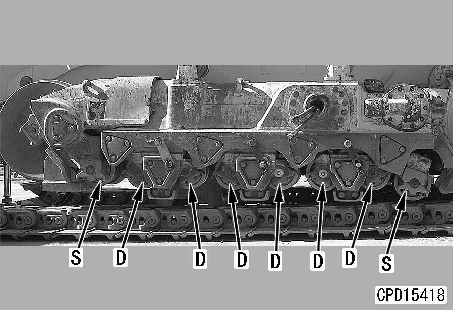
After removing tool L13, replace the mounting bolts of cover (3) with the regular parts.
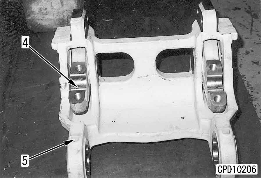
3 Cover mounting bolt: 883 – 1,470 Nm {90 – 150 kgm} a Install the track roller assembly with the oil filler plug out. a After installing the track roller assembly, set the position of dowel pin (4).
2 Track roller assembly mounting bolt: Adhesive (LT-2)
3 Track roller assembly mounting bolt: 2,205 – 2,695 Nm {222 – 275 kgm}
[*2]
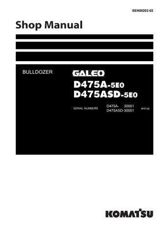
Install S to the first and last track rollers and install D to the other track rollers.
S: Single flange
D: Double flange
[*3]
When using the assembling tool
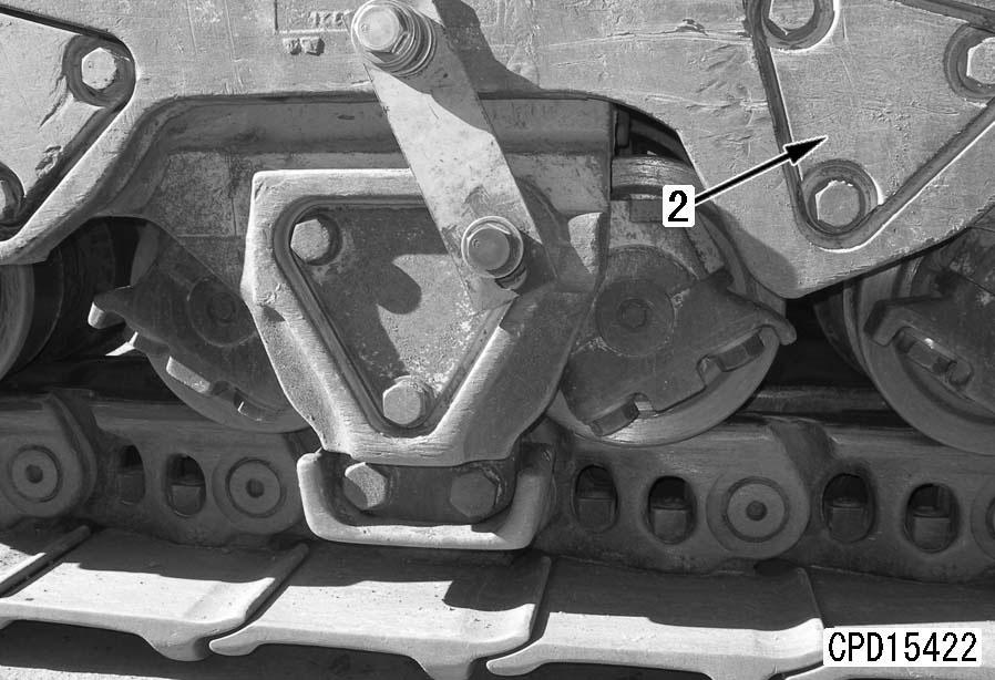
Set tool L12 under the track roller assembly (2) and lift up and set track roller assembly (2) to the track frame.
Disassembly and assembly of track roller assembly
Special tools
Disassembly
1.Remove oil filler plug and drain oil.
6 Track roller: 1.4 – 1.5 l a Keep the floating seal in a safe place to protect it from damage. a Keep the floating seal in a safe place to protect it from damage.
2.Set track roller assembly (1) on block [1].
3.Remove mounting bolts, then using forcing screws [2], remove seal guide (2) together with retainer (3) and plate (4).
4.Turn over track roller assembly.
5.Remove mounting bolts, then using eyebolts [3], remove shaft (5) together with retainer.
6.Using press, remove seal guide (6) together with retainer (7) and plate (8) from shaft.
7.Remove seal guides (2) and (6) from retainers (3) and (7).
8.Remove floating seal (9) from seal guides (2) and (6).
9.Remove floating seal (10) from retainers (3) and (7).
10.Remove bushing (11) from roller (12).
Assembly
a Clean all parts, and check for dirt or damage.
1.Set roller (12) to press, then using tool L8, press fit bushing (11).
a First, center the bushing with a plastic hammer, then press fit with a press.
a Press fit so that press-fitting dimension (a) from the end face of the roller to the top surface of the bushing is the dimension given below.
q Press-fitting dimension (a): 17 ± 0.5 mm a Check that the plate can be turned smoothly with the hand. a Press fit the seal guide so that press-fitting dimension (b) from the end face of the shaft to the top surface of the seal guide is the dimension given below. q Press-fitting dimension (b): 86 ± 0.2 mm a Turn over the track roller assembly and press fit seal guide (6) on the opposite side according to the above procedure.
2.Set shaft (5) to roller.
3.Using tool L9, install floating seal (10) to retainers (3) and (7).
4.Fit O-ring and install retainers (3), (7) and plate (8) to roller.
5.Using tool L9, install floating seal (9) to seal guides (2) and (6).
6.Using tool L10, press fit seal guide (2) to shaft. a Seal guide press-fitting force: 49 – 83 kN {5 – 8.5 ton}
7.Using tool L11, fill with oil to specified level, then tighten oil filler plug.
5 Track roller: 1.4 – 1.5 l (GO140)
3 Oil filler plug: 156.8 – 254.8 Nm {16 – 26 kgm}
Removal and installation of carrier roller assembly
Removal
1.Loosen the track shoe. For details, see Expanding track shoe assembly.
2.Lift up the track shoe with hydraulic jack [1].
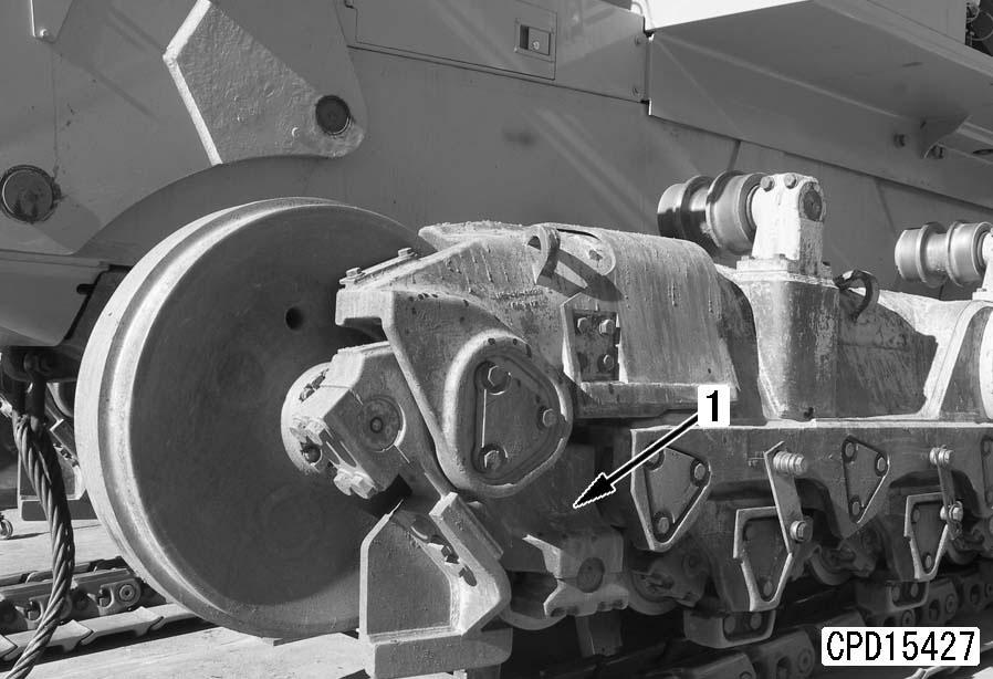
3.Lift off carrier roller assembly (1). [*1]
4 Carrier roller assembly: 105 kg
Installation q Carry out installation in the reverse order to removal.
[*1] a Make a clearance (a) of 5 mm between the carrier roller and support as shown below.
2 Carrier roller assembly mounting bolt: Adhesive (LT-2)
3 Carrier roller assembly mounting bolt: 744.8 ± 83.3 Nm {76 ± 8.5 kgm}
Disassembly and assembly of carrier roller assembly
Special tools
5.Using tool L7, remove nut (4).
6.Remove the fitted part of the seal guide with puller [2] and remove bearing (5) and roller (6) as one unit by using eyebolts.
Disassembly
1.Remove the oil filler plug and drain the oil. a Drain the oil, turning the shaft.
6 Carrier roller: Approx. 13 l a Press fit the bearing inner race, turning the roller, until the roller becomes a little hard to turn.
2.Set carrier roller assembly (1) to block [1].
3.Remove the mounting bolts and cover (2).
4.Remove ring (3).
7.Remove bearing outer race (7) from the roller.
8.Remove seal guide (8) and bearing inner race (9) as one unit with puller [3].
9.Remove floating seal (10) from seal guide (8).
10.Remove seal guide (11) with push tool [4].
11.Remove floating seal (12) from seal guide (11).
Assembly a Clean the all parts and check them for dirt.
1.Press fit bearing inner race (9) with push tool [5].
2.Press fit bearing outer race (7) with push tool [6].
5.Tighten nut (4) with tool L7.
3 Nut: 98 Nm {10 kgm} a After the nut is tightened, if its hole is not matched to the hole of the shaft, match its hole by loosening the nut.
6.Install ring (3).
7.Fit the O-ring to cover (2) and install them.
8.Install floating seal (10) to seal guide (8) with tool L5
9.Fit the O-ring to seal guide (8) and install them, matching them to the dowel pin.
12.Supply specified quantity of oil by using tool L4 and tighten the oil filler plug.
5 Carrier roller: 1.25 – 1.35 l (GO140)
3 Oil filler plug: 157 – 255 Nm {16 – 26 kgm}
10.Install floating seal (12) to seal guide (11) with tool L5
11.Press fit seal guide (11) with tool L6 a Press fit the seal guide so that dimension (a) between the shaft end and seal guide top will be 181.25 ± 0.2 mm.
Removal and installation of bogie assembly
Special tools
Removal
1. Loosen the track shoe. For details, see Expansion and installation of track shoe assembly.
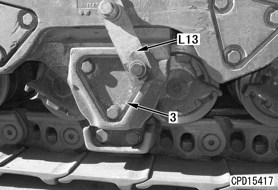
2. Install tool L13 and secure the bogie assembly.
3. Operate the blade and ripper to lift the machine body until the track roller assembly separates from the track link. k Set a block between the track roller and track link so that the machine body will not lower.
4. Set block [1] out of the track shoe, matching it to the height of the track link.
5. Set steel plate [2] on the track shoe and block [1].
6. Operate the blade and ripper to lower the machine body until the track roller of bogie assembly (1) comes in contact with steel plate [2].
a Operate the blade and ripper slowly, running the engine at the low idling speed.
7. Remove cover (2).
4)Set tool L15.
5)Pull out spacer (6) and rings (7) and (8). a Pulling out force: 225.5 – 460.9 kN {23 – 47 tons}
8.Pulling
1)Set tool L14
2)Push out shaft (3) and ring (4) to the opposite side simultaneously. a Pushing out force: 225.5 – 460.9 kN {13 – 47 tons} a Store the floating seals so that they will not be damaged.
6)Remove spacer (6).
7)Remove spacer (9) and floating seals (10) between rings (7) and (8). a Store the floating seals so that they will not be damaged.
8)Pull out the shaft and rings on the opposite side according to above steps 1) – 7).
3)Remove floating seals (5) from the end faces of rings (4) and (7).
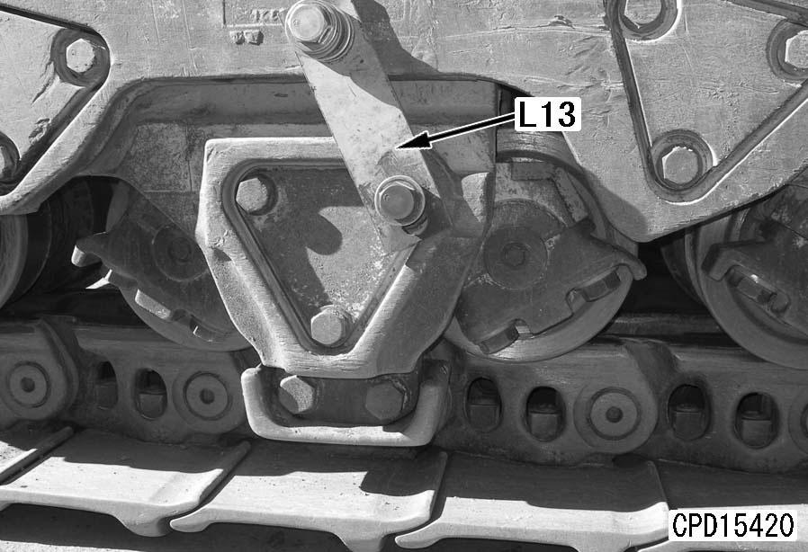
9. Remove tool L13 k Set a block between the track roller and track link so that the machine body will not lower.
10. Place bogie assembly (1) on steel plate [2].
11. Operate the blade and ripper to raise the machine body until the bogie assembly can be pulled out.
12. Sling bogie assembly (1) and pull it out, sliding it on steel plate [2].
4 Bogie assembly: 1,200 kg
2)Press fit shaft (3) to ring (8).
3)Install spacer (9).
4)Press fit ring (7) to shaft (3).
5)Install spacer (6).
6)Press fit ring (4) to shaft (3).
2 Apply lubricant (LM-P) to parts (a) (about 10 mm) of rings (8) and (4).
Installation
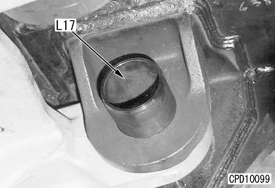
1.Assembly of pin assembly a When installing the floating seals, completely degrease the O-rings and O-ring contacting surfaces. a Check that each floating seal is not inclined more than 1 mm.
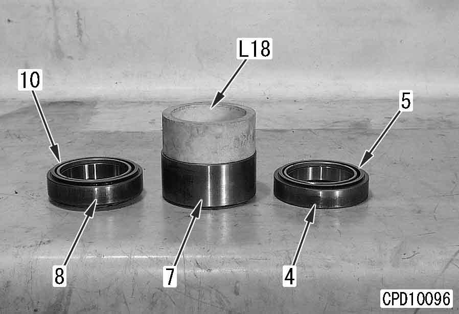
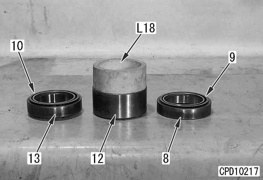
1)Using tool L18, install floating seals (5) to rings (4) and (7) and install floating seals (10) to the opposite side of ring (7) and ring (8).
2. Apply lever block [3] between the guard of bogie assembly (1) and the bogie assembly on the opposite side. Slide bogie assembly (1) on the steel plate to set it to the mounting position.
4.Press fitting of pin assembly
1)Set tool L16 and cover (2).
5.Refilling with oil
Supply the specified quantity of oil by using tool L19 a Oil supplying pressure: 0.49 MPa {5 kg/cm2}
5 Pin assembly: 180 – 200 cc (GO-140) a Direct arrow (a) on the end face of the pin assembly up (when the pin assembly is installed to the machine). a Push in the pin assembly with cover (2). a Push in the pin assembly to machined face (b) of the bogie. a Total press fitting force of pin assembly: 294.2 – 490.5 kN {30 – 50 tons}
2)Press fit pin assembly (11).
2 Apply lubricant (LM-P) all over the side of the pin assembly.
6. Press fit the pin assembly on the opposite side of the bogie according to above steps 3 and 4.
7. Tighten the mounting bolts of pin assembly cover (2) (2 places on inside and outside).
3 Cover mounting bolt: 883 – 1,470 Nm {90 – 150 kgm}
8. Adjust the tension of the track shoe. For detail, see Testing and adjusting, "Testing and adjusting track shoe tension".
Disassembly and assembly of bogie assembly
Special tools
Disassembly
1.Track roller assembly
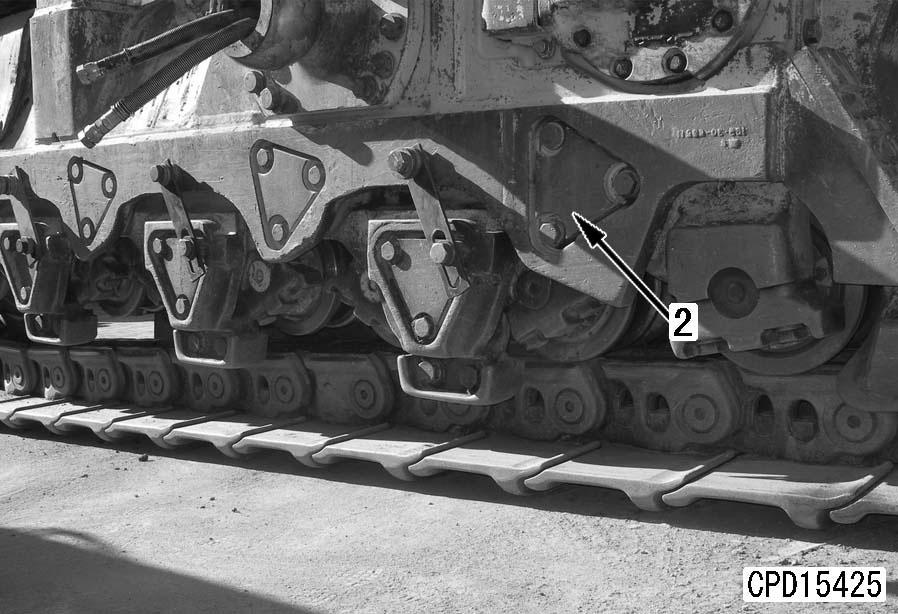
Turn over bogie assembly (1) and lift off 2 track roller assemblies (2).
3. Disassemble the pin assembly according to Removal and installation of bogie assembly (Step 8).
4.Disconnection of bogie
Disconnect inner bogie (4) and outer bogie (5).
Assembly
1.Assembly of pin assembly
Assemble the pin assembly according to Removal and installation of bogie assembly (Steps 3 – 5 of Installation).
2. Set inner bogie (4) to outer bogie (5).
3.Press fitting of pin assembly a Direct arrow (a) on the end face of the pin assembly up (when the pin assembly is installed to the machine). a Push in the pin assembly with cover (3). a Push in the pin assembly to the machined face (b) of the bogie and secure the level difference of 5 mm between the bogie and pin assembly. a Total press fitting force of pin assembly: 294.2 – 490.5 kN {30 – 50 tons}
1)Set tool L16 and cover (3).
2. Remove cover (3).
2)Press fit the pin assembly.
2 Apply lubricant (LM-P) all over the side of the pin assembly.
5. Press fit the pin assembly on the opposite side of the bogie according to above steps 3 and 4. a After press fitting the pin assembly, rock the small bogie so that it can be moved with light force.
6. Tighten the mounting bolts of pin assembly cover (3) (2 places on inside and outside).
3 Cover mounting bolt: 883 – 1,470 Nm {90 – 150 kgm}
7.Track roller assembly
Sling and install 2 track roller assemblies (2) to bogie assembly (1).
2 Track roller mounting bolt: Adhesive (LT-2)
3 Track roller mounting bolt: 2,205 – 2,695 Nm {225 – 275 kgm}
4.Refilling with oil
Supply the specified quantity of oil by using tool L19 a Oil supplying pressure: 0.49 MPa {5 kg/ cm2}
5 Pin assembly: 180 – 200 cc (GO140)
Removal and installation of No.1 bogie assembly
Special tools
Removal k Set a block between the track roller and the track link to prevent the chassis from coming down.
1. Loosen track shoe tension. For details, see Expansion and installation of track shoe assembly.
2. Operate blade and ripper, and raise chassis to a position where track roller of No. 2 bogie assembly is separated from track link.
3. Fit eyebolts to holes of pad mounting bolt (M12 x 2) portion at rear of No. 1 bogie assembly, and raise No. 1 bogie assembly (1).
4. Put steel plate between track shoe and roller, then loosen roller cap bolts (2) approx. 20 mm. (Both inside and outside) q There is a dowel pin on the near side of the track roller assembly, so be careful not to break it. (Dowel pin insertion tolerance: 5 – 6 mm)
5. Tap end face of shaft (3) with hammer and remove track roller assembly (4).
6. Remove roller cap bolt (2), then put track roller assembly (4) on steel plate, and pull out.
4 Track roller assembly: 240 kg
7. Raise No. 1 bogie (5) with tool L20 and hold in position.
8. Remove cover (6).
9.Pulling out shaft and ring
1)Set tool L14 a Pushing out force:
2)Push out shaft (7) and ring (8) to the opposite side simultaneously.
225.5 – 460.9 kN {13 – 47 tons} a When the ring is pushed out, it interferes with the idler. Accordingly, supply grease to the track tension adjustment parts in advance and move the idler cushion assembly to the front side of the machine body. a Store the floating seals so that they will not be damaged.
3)Remove floating seals (9) from the end faces of rings (8) and (12).
4)Set tool L15 a Pulling out force: 225.5 – 460.9 kN {23 – 47 tons} a Store the floating seals so that they will not be damaged.
5)Pull out spacer (11) and rings (12) and (13).
6)Remove spacer (11).
7)Remove spacer (14) and floating seals (10) between rings (12) and (13).
10. Lower bogie (5) on the steel plate and pull it out.
4 Bogie assembly: 180 kg
2)Press fit shaft (7) to ring (13).
3)Install spacer (14).
4)Press fit ring (12) to shaft (7).
5)Install spacer (11).
6)Press fit ring (8) to shaft (7).
2 Apply lubricant (LM-P) to parts (a) (about 10 mm) of rings (13) and (8).
Installation
1.Assembly of pin assembly a When installing the floating seals, completely degrease the O-rings and O-ring contacting surfaces. a Check that each floating seal is not inclined more than 1 mm.
1)Using tool L18, install floating seals (9) to rings (8) and (12) and install floating seals (10) to the opposite side of ring (12) and ring (13).
2. Slide bogie (5) on steel plate [1] to the center.
3. Set bogie (5) to the mounting position with tool L20
5.Press fitting of pin assembly
1)Set tool L16 and cover (6).
6.Refilling with oil
Supply the specified quantity of oil by using tool L19 a Oil supplying pressure: 0.49 MPa {5 kg/ cm2}
5 Pin assembly: 180 – 200 cc a Direct arrow (a) on the end face of the pin assembly up in the mounting state on the machine body. a Push in the pin assembly with cover (6). a Push in the pin assembly to machined face (b) of the bogie and secure the level difference of 5 mm between the bogie and pin assembly. a Total press fitting force of pin assembly:
2)Press fit the pin assembly (11).
2 Apply lubricant (LM-P) all over the side of the pin assembly.
294.2 – 490.5 kN {30 – 50 tons}
7. Press fit the pin assembly on the opposite side of the bogie according to above steps 5 and 6.
8. Install covers (6) (2 places on inside and outside).
9. Install eyebolts instead of the pad mounting bolts (M12 x 2 pieces) of bogie (5) and lift and hold the bogie.
10. Insert tool L21 in the shaft of track roller assembly (4), then lift and balance the track roller assembly and set it on the track shoe.
4 Track roller assembly: 220 kg
11. Lower the machine body slowly. When the clearance between bogie (5) and shaft (3) becomes about 20 mm, install cap (15) and secure it with bolts (2) temporarily.
12. Matching the dowel pin holes, tighten bolts (2).
2 Cap mounting bolt: Adhesive (LT-2)
3 Cap mounting bolt: 2,205 – 2,695 Nm {225 – 275 kgm}
13. Adjust the tension of the track shoe. For detail, see Testing and adjusting, Testing and adjusting track shoe tension.