45 minute read
Undercarriage and frame, Part 2


Expansion and installation of track shoe assembly 1
Expansion
Checking before expansion of track shoe assembly k In some cases, it may be extremely dangerous to expand the track shoe assembly. To prevent danger, carry out the following checks before expansion of the track shoe assembly. k Never loosen the lubricator more than one turn. q Loosen lubricator (1) at the adjustment cylinder, release the grease, then move the machine backwards and forwards a short distance, and check that the track tension is relieved. a If the shoe tension is relieved, go to "Expansion of track shoe assembly (Normal)".
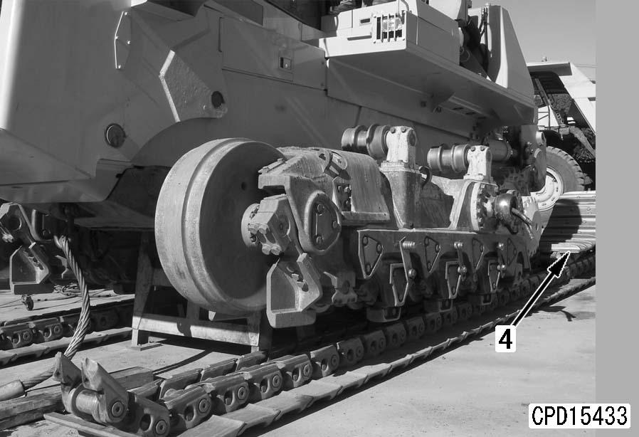
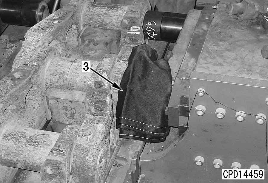
Expansion of track shoe assembly (Normal) a If Checking before expansion of track shoe assembly shows that there is no abnormality, do as follows. a Bring the master link above the idler (just behind the center). a Set blocks [1] and [2] at the front end of the idler and between the carrier rollers so that the mating faces of the master link will not open until the master bolt is removed. q If the above procedure does not relieve the track tension and the track shoe assembly remains tense, there may be an abnormality inside the track frame (the recoil spring case is broken, the recoil spring set bolt is broken, or the nut at the end of shaft has fallen off). a If the shoe tension is not relieved, go to "Expansion of track shoe assembly (when there is abnormality inside track frame)".
1.Set master link in position.
2.Relieve track shoe tension.[*1] k Never loosen lubricator (1) more than one turn. a If the track is not relieved by loosening the lubricator, move the machine backwards and forwards.
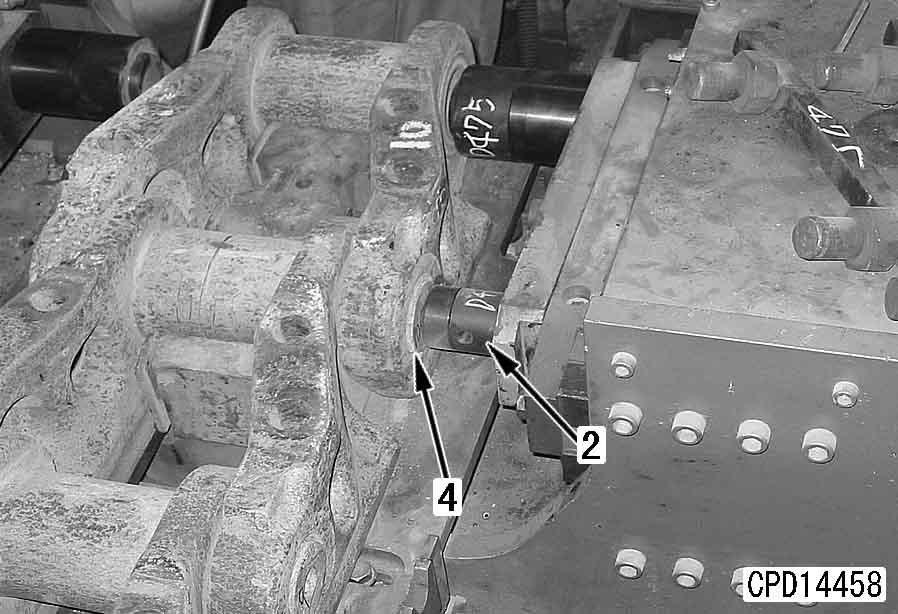
3.Remove track shoe (2).[*2] a Loosen each of the 4 bolts by 1 – 2 turns. Check that the 4 bolts can be turned lightly, then pull them out. Do not pull out only 1 bolt without loosening the other three. a If a bolt is turned forcibly while it cannot be turned lightly, the threads of it and master link (3) may be damaged. k Never loosen lubricator (1) more than one turn. a Check that all the grease has been removed. a Length of track: Approx. 12.5 m k To prevent danger, never stand in front of the idler yoke assembly.
1.Remove work equipment assembly. For details, see "Removal and installation of work equipment assembly".
2.Loosen lubricator (1), then move machine backwards and forwards to remove grease.
4.Raise tip of master link, move machine towards rear slowly, and lay out track shoe assembly (4).
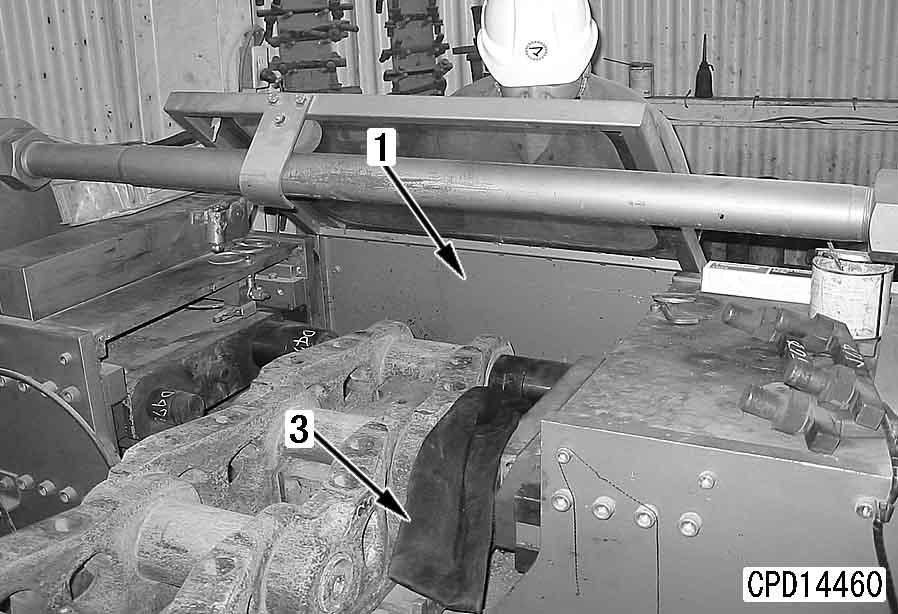
3.Drive slowly forward to put track shoe at idler end in contact with large block [3] or a wall (if another large bulldozer of the same capacity as the machine being repaired is available, put in contact with the blade). Stop machine when recoil spring bends and slack is formed in track shoe assembly, then apply brake. When doing this, set so that master link is between idler and front carrier roller. For safety reasons, fit a lever block between carrier roller support and link.
4.Remove shoe (2), then disconnect master link (3).
5.Move machine towards rear slowly and lay out track shoe assembly.
Expansion of track shoe assembly (when there is abnormality inside track frame)
a When "Checking before expansion of track shoe assembly" shows any abnormality, do as follows.
k If there is any abnormality inside the track frame, there is danger that the track shoe assembly may spring back when it is removed or that the idler may spring out when the track shoe assembly is removed. This may lead to serious injury, so expand the track shoe assembly as follows.
D475A, D475ASD-5E0
Installation
q Carry out installation in the reverse order to expansion (normal).
[*1] a For details of the track shoe tension, see Testing and adjusting, Testing and adjusting of track shoe tension. a Tighten all of the 4 bolts with the fingers until the master link contacting faces are fitted to each other. a If a bolt is tightened forcibly before the master link contacting faces are fitted to each other, the threads of that bolt and the master link may be damaged.
[*2] a Tighten the master link shoe mounting bolts in the order shown in the diagram below.
2 Shoe mounting bolt: Seizure prevention compound (Maruzen Molymax No. 2 or equivalent)
3 Shoe mounting bolt:
1st step: 980 ± 98 Nm {100 ± 10 kgm}
2nd step: Tighten a further 180 ± 10°
Overall disassembly and overall assembly of track shoe
Special tools
SymbolPart
No.Part Name
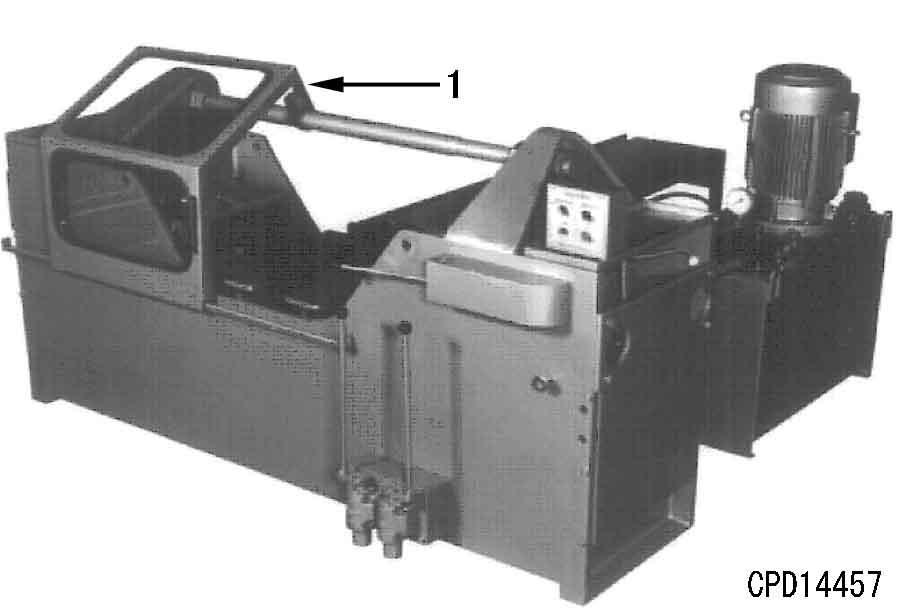
Overall disassembly a When disassembling the track shoe, see shop manual – Guidance for reusable parts – Lubricated tracks (III) (Form No.: SEBG4092). a Check that the track press has protective cover (1).
2791-660-7460Pin brush t 1
3791-646-7900Push tool t 1
4791-932-1110Push tool t 1
5 790-701-3000 and 791-601-1000
Seal checker Oil pump t 1
6791-632-1010Installer t 1 9
1791-685-5600 Push tool assembly t 1N
2791-685-5640•Adapter1N
3791-685-5660•Ring1N
4791-685-5670•Plate1N
5791-685-5680•Ring1N
6791-685-5690•Push tool1N
7791-685-5710•Adapter1N
8791-685-5720•Spring1N
9791-685-5730•Bar1N
1001252-30655•Bolt1
1791-685-5700 Push tool assembly 1N
2791-685-5650•Adapter1N
3791-685-5660•Ring1N
4791-685-5670•Plate1N
5791-685-5680•Ring1N
12
6791-685-5690•Push tool1N
7791-685-5710•Adapter1N
8791-685-5720•Spring1N
9791-685-5730•Bar1N
1001252-30655•Bolt1
1101580-01210•Nut1
13791-685-5750Push tool t 1N a The track press operator and other workers must put on helmets, safety glasses and earplugs.
1.Removal of shoe a If a shoe bolt is still hard (If its torque is not lowered to 0) after it is unscrewed by 1 turn, loosen the other bolts, and it can be removed easily. a If a bolt is unscrewed forcibly while its torque is not 0, it will stick to the link and will need to be repaired. a When moving the shoe assembly, take care not to damage the master link. a If it is obliged to cut a shoe nut with gas, keep the temperature of the sealing parts below 80°C and prevent the spatters from entering the clearance of the link so that the sealing parts will not be deteriorated by the heat.
Sling the shoe assembly and set it on a floor with the shoe up. Remove the shoe with a shoe bolt impact wrench.
2.Disassembly of link
1)Set the link assembly on the link press and hit it with a hammer so that the bushing will be fitted to the jaw.
a If the link tread, outside of the bushing, etc. are worn, adjust the height of the jaw or guide plate to align the disassembly jig with the pin and bushing so that the link hole will not be damaged during disassembly.
a If the above parts are not aligned perfectly, the link hole may be damaged and the pin and bushing may be broken during disassembly.
a Drive the small plug of the pin inward with tool R1 after disassembly to avoid making the workshop dirty.
2)Operate the left cylinder to pull out the fitted parts of the left link, pin, and bushing simultaneously.
a Check the pulling out force of the pin and bushing to see if the necessary fitting force of the pin and bushing is obtained when they are turned over and assembled.
a When the wedge link is cut, it bangs. This phenomenon is normal.
4)Return the right cylinder and take out the links, pins, bushings, and spacers on both sides, then send the next link assembly to the jaw.
a If the end faces of the bushings and sealing surfaces are damaged, oil will leak. Accordingly, handle them with care.
a Take care not to scratch your hands with the sharp edges of a cut wedge link.
3)Return the left cylinder and operate the right cylinder to pull out the right link, pin, and bushing simultaneously.
3.Inspection
Inspect the following items to see if the parts can be reused for an oil lubricated track or a grease lubricated track, then generally examine whether the link assembly should be recycled as an oil lubricated track or as an grease lubricated track.
a For judgment of recycling of the parts, see shop manual – Guidance for reusable parts – Lubricated tracks (III) (Form No.: SEBG4092).
1)Check the parts visually for damage, then apply a dye penetrant test or a magnetic flaw test to the parts which seem to be damaged. Discard a cracked part since it cannot be reused.
2)Measure the outside diameters of the fitting parts of the pin and bushing and those of the pin and bushing fitting parts of the link with a micrometer and a cylinder gauge to see if the allowable interference is obtained. When reusing the parts for an oil lubricated track, the pin and link must have the standard interference.
a If the allowable interference is not obtained, replace the parts with new ones.
a For the criteria, see “Maintenance standard”.
a Precautions for storage
3)Store the seal without removing it from the link to prevent rusting of the counterbore of the link, taking care not to damage the seal lip.
4)Apply rust-preventive oil to the pin and bushing fitting parts and shoe and master link mating faces of the link.
5)Apply rust-preventive oil all over the pin, bushing, and spacer. In particular, take care not to damage the end faces of the bushing.
Overall assembly
a When assembling the track shoe, see shop manual – Guidance for reusable parts – Lubricated tracks (III) (Form No.: SEBG4092).
When recycling for oil lubricated track
1.Preparation work
1)Cleaning of seal assembly a Since the seal ring and load ring are deteriorated easily by cleaning liquid (trichloroethylene, etc.), clean them quickly. After cleaning them, wipe off the cleaning liquid. a If the corners of the pin end are worn and sharpened, they may scuff the fitting parts to cause oil leakage. a Coat the plug with GO90 and drive it with the smaller end ahead. a Since the parts are rusted easily, clean them just before assembling them. a Do not repair the end faces of the bushing with a grinder, etc. since that can cause oil leakage.
Take the seal assembly out of the link and divide it into the seal ring and load ring, then clean them.
2)When reusing the pin, chamfer the corners of its end smoothly with a grinder. Remove the projections of the fitting parts with the grinder.
1]Insert the plug in the hole of the guide through the plug inserting hole.
2]Push the bar with the hand and insert the plug until it stops.
3]Push the plug with the bar to press the guide against the pin.
4]Drive the bar with a hammer. a Driving distance (a) from pin end: 10 ± 1 mm a If the edge of the pin hole is worn and sharpened, chamfer it with a small grinder (wheel tip angle: 45 – 60°) so that the plug will not be damaged.
3)Clean the link, pin, bushing, and spacer, if they are dirty. Remove the projections of the link and bushing with the grinder.
4)If the large plug has been driven out, drive it with tool R3
Clean the pin hole with tool R2 in advance.
5)Installation of seal assembly
Clean the counterbore of the link carefully and push in the seal to the bottom with tool R6 a If any oil sticks to the counterbore of the link and seal assembly, the seal turns and its sealing performance is lowered. Accordingly, do not apply any oil. Take care that oil will not stick to the seal when the seal is inserted in the counterbore. a For the standard dimensions, see “Press-fitting jig di mension table for link press”. a If the pin end (Part P) and link sides (Parts Q and R) are worn, count in the quantity of the wear when adjusting the dimensions of the fitting jig so that the pin and bushing will be projected by the same distance on both sides.
6)Adjust the dimensions of the fitting jig of the link press to keep the projection distance of the pin and bushing constant and keep the fitting dimensions of the seal within the limits when those parts are assembled.
2.Assembly of link
1)Apply oil (GO90) between the pin and bushing with a clean brush, then set them on this side of the link press jaw.
a When reusing (turning) the bushing, set its worn side to the shoe fitting face of the link (which is directed up on the link press).
7)Adjust the relief pressure of the link press so that the pressing force will not exceed the specified value.
a If the pressing force is too large, the spacer is pressed against the bushing with an excessive force. As a result, the spacer may be broken or it and bushing end may be worn abnormally.
a Press cutting force of pin and bushing: 1,274 kN {130 tons}
Press cutting force C a At this time, use the pin-side master links as supports. a Fitting force of bushing: 245 – 382 kN {25 – 39 tons} a Remove the all chips made when the bushing is press fitted by blowing air against them. a Adjust the fitting jig of the link press so that the bushing will be projected by the same distance on both sides. a Check that the sealing surface and bush ends are free from dirt and apply oil (GO90) to them with a clean cloth or brush. a Clean the spacer with a clean cloth before installing it. a When reusing the pin, install it with its side hole on the link tread side similarly to a new one. If it is not installed in this direction, its strength may lower. Accordingly, make a mark of the side hole on the end face of the pin. a If the jigs shake while the pin and bushing are press fitted, the seal may come off the link. Accordingly, press fit smoothly. If the seal comes off the link, stop press fitting and install the seal to the link correctly, then start press fitting again. a Press fitting force of pin and bushing: 578 – 833 kN {59 – 85 tons} a Apply oil similarly to the right link. a Adjust the depth of the receiving jig so that the pin will be projected by the same distance on both sides. a When press fitting, take care that the seals and spacers on both sides will not come off. Press fitting force of link: 578 – 833 kN {59 – 85 tons} a Actually, you cannot see from outside if the above parts are fitted. Accordingly, control the hydraulic pressure of the link press. Set the relief pressure to a proper level and heighten the hydraulic pressure to that level. For setting of the relief pressure, see Preparation work. a Check that adjacent 2 links can turn around each other.
1.8 x Average press fitting force (Set the press cutting force by adjusting the relief pressure of the link press.)
2)Press fit both bushing-side master links to the bushings with the shoe fitting faces up.
3)Measure the distance between the shoe bolt holes of both links with a shoe bolt hole pitch gauge. Press fit the master link until the specified shoe bolt hole pitch is obtained.
4)Turn over the master links and check that they are press fitted in parallel.
7)Apply gasket sealant (198-32-19890) to the pin fitting hole of the link to prevent oil from oozing through the scuffs of the pin fitting parts.
5)Measure the projections of the bushing on both sides with a depth gauge.
8)Set the right link and install the spacer to the pin.
6)Send out the master link and set the next pin and bushing.
9)Set the right jig on the receiving side and the left jig on the pushing side and press fit the pin and bushing simultaneously.
11)Set the left link and install the spacer to the pin.
10)Using the spacer for fine adjustment, press fit the pin until it is fitted to the lower part of the pin end receiving jig.
12)Set the left jig on the receiving side and the right jig on the pushing side and press fit the left link.
13)Press fit until the link, spacer, and bushing are fitted to each other.
15)Install a If the distance between the shoe bolt holes is longer than the limit, disassemble and check for abnormality, then press fit again. a If the distance between the shoe bolt holes is shorter than the limit and the shoe cannot be installed, the spacer or bushing end may be worn more than the allowable limit. In this case, disassemble and replace the parts.
14)Measure the distance between the shoe bolt holes with a shoe bolt hole pitch gauge and check that the result is within the limits.
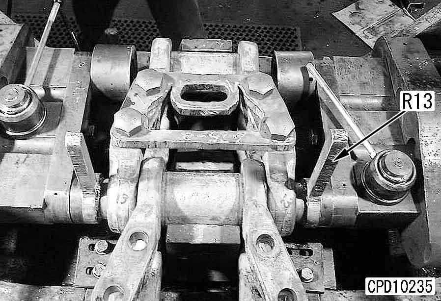
18)Push in the ring with jig R13 Pushing force of ring: 392 – 490 kN {40 – 50 tons} a In a cold or very cold district, supply Komatsu genuine oil (150-09-19270 or 195-32-61990) having better lowtemperature characteristics instead of GO90. a If the oil pressure is heightened too much, it has bad effects on the seal. Take care. a Keep the degree of vacuum inside the pin at 91 – 95 kPa {680 – 710 mmHg} for 5 seconds and check that the pressure does not change. If the pressure changes, disassemble and check the seal. If the seal is free from abnormality, assemble again. a Supply oil so that the depth L of the hollow of the pin hole will be in the following range when the link is left with the small plug side up (when the link assembly is placed on its side) for 30 minutes.
20)Supply oil (GO90) with tool R5 until the oil supply pressure rises to 196 – 294 kPa {2 – 3 kg/cm2}.
19)After each link is assembled, bleed air from the pin with tool R5 and check the sealing performance.
Dimension L: 40 – 70 mm
21)After supplying oil, drive in the small plug to the specified position with tool R4 a Apply GO90 around the small plug. a Drive in the plug to the following depth.
Driving depth from end: 7.5 ± 1 mm a Check that the master links on both sides are press fitted in parallel.
22)Assemble the master link on the pin side at last.
2)When installing a double track, place the assembled double shoes on a level place in 1 line with the shoe side up. Pull pinside master link (1) and bushing-side master link (2) together and set them to each other by the mating faces. Place shoe (3) on the links and check that master bolts (4) can be tightened easily by hands until the mating faces of the links are fitted together, and then connect the master links.
1)Set the link assembly on the bed and install the shoe with a shoe bolt impact wrench and a torque wrench.
2 Shoe bolt: Lubricant containing molybdenum disulfide (LM-P)
3 Shoe bolt (Regular link)
Initial torque: 784 ± 78 Nm {80 ± 8 kgm}
Retightening angle: 180 ± 10°
2 Shoe bolt:
Lubricant containing molybdenum disulfide (LM-P)
3 Shoe bolt (Master link)
Initial torque: 980 ± 98 Nm {100 ± 10 kgm}
Retightening angle: 180 ± 10° a Tighten the bolts in the order of [1] –[4].
When recycling for grease lubricated track 1.Preparation work
1)Cleaning of seal assembly a Since the seal ring and load ring are deteriorated easily by cleaning liquid, clean them quickly. After cleaning them, wipe off the cleaning liquid.
Take the seal assembly out of the link and divide it into the seal ring and load ring, then clean them.
4)Clean the outside of the pin, surfaces of the spacer, and end faces and inside of the bushing, if they are dirty.
5)Apply grease to the outside of the pin and surfaces of the spacer.
2)When reusing the pin, chamfer the corners of its end carefully with a grinder so that it will be press fitted smoothly.
6)Installation of seal assembly
Clean the counterbore of the link carefully and push in the seal to the bottom with tool R6 a If any grease sticks to the counterbore of the link and seal assembly, the seal turns and its sealing performance is lowered. Accordingly, do not apply any grease.
3)Drive the large plug and small plug with tools R3 and R4
1]Insert each plug in the hole of the guide through the plug inserting hole. (Apply oil to the plug.)
2]Push the bar with the hand and insert the plug until it stops.
3]Push the plug with the bar to press the guide against the pin.
4]Drive the bar with a hammer. a Driving distance (a) from pin end: Small plug: 7.5 ± 1 mm
Large plug: 10 ± 1 mm a If the plugs were not pull out of the pin when disassembled, use them as they are. a For the standard dimensions, see “Press-fitting jig di mension table for link press”. a If the pin end (Part P) and link sides (Parts Q and R) are worn, count in the quantity of the wear when adjusting the dimensions of the fitting jig so that the pin and bushing will be projected by the same distance on both sides. a Fitting force of bushing: 245 – 382 kN {25 – 39 tons}
7)Adjust the dimensions of the fitting jig of the link press to keep the projection distance of the pin and bushing constant and keep the fitting dimensions of the seal within the limits when those parts are assembled.
2)Press fit both bushing-side master links to the bushings with the shoe fitting faces up. a At this time, use the pin-side master links as supports.
2.Assembly of link
1)Apply lithium grease (G2-LI) between the pin and bushing, then set them on this side of the link press jaw.
a When reusing (turning) the bushing, set its worn side to the shoe fitting face of the link (which is directed up on the link press).
3)Measure the distance between the shoe bolt holes of both links with a shoe bolt hole pitch gauge. Press fit the master link until the specified shoe bolt hole pitch is obtained.
a Remove the all chips made when the bushing is press fitted by blowing air against them.
4)Turn over the master links and check that they are press fitted in parallel.
5)Measure the projections of the bushing on both sides with a depth gauge.
a Adjust the fitting jig of the link press so that the bushing will be projected by the same distance on both sides.
6)Send out the master link and set the next pin and bushing.
a When reusing the pin, install it with its side hole on the link tread side similarly to a new one. If it is not installed in this direction, its strength may lower. Accordingly, make a mark of the side hole on the end face of the pin.
a If the outside of the pin is worn, set it with the un-worn part on the traction side. In this case, install it with its side hole on the link tread side, too.
7)Set both links and operate both pushing jigs to press fit the pin and bushing simultaneously.
a If the jigs shake while the pin and bushing are press fitted, the seal may come off the link. Accordingly, press fit smoothly. If the seal comes off the link, stop press fitting and install the seal to the link correctly, then start press fitting again.
a Press cutting force of pin and bushing: 1,274 kN {130 tons} Press cutting force C
1.8 x Average press fitting force (Set the press cutting force by adjusting the relief pressure of the link press.)
8)Measure the distance between the shoe bolt holes with a shoe bolt hole pitch gauge. If the result is within the limits, stop press fitting.
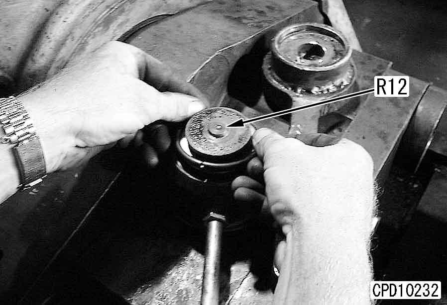
9)Install the ring to jig R12 a Check that the master links on both sides are press fitted in parallel.
12)Assemble the master link on the pin side at last.
3.Shoe (Regular link)
Set the link assembly on the bed and install the shoe with a shoe bolt impact wrench and a torque wrench.
2 Shoe bolt:
Lubricant containing molybdenum disulfide (LM-P)
3 Shoe bolt (Regular link)
Initial torque: 784 ± 78 Nm {80 ± 8 kgm}
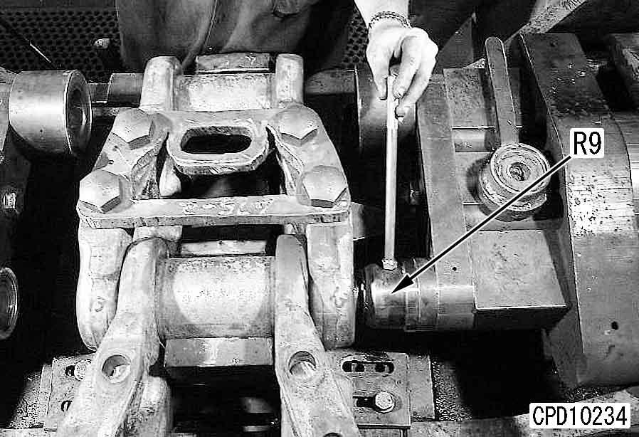
10)Match the jig to the pin hole and push it in until the ring is inserted in the pin groove. Similarly, insert the ring on the opposite side with jig R9 a A sound is made when the ring is inserted in the pin.
Retightening angle: 180 ± 10°
11)Push in the ring with jig R13 Pushing force of ring: 392 – 490 kN {40 – 50 tons}
4.Assembly of 1/2 track
Place the assembled 2 shoes on a level place in 1 line with the shoe side up. Pull pin-side master link (1) and bushing-side master link (2) together and set them to each other by the mating faces. Place shoe (3) on the links and check that master bolts (4) can be tightened easily by hands until the mating faces of the links are fitted together, and then connect the master links.
2 Shoe bolt: Lubricant containing molybdenum disulfide (LM-P)
3 Shoe bolt (Master link)
Initial torque: 980 ± 98 Nm {100 ± 10 kgm}
Retightening angle: 180 ± 10° a Tighten the bolts in the order of [1] – [4].
Press-fitting jig dimension table for link press
Field disassembly and assembly of one link
Special tools
1791-832-1490Push
2791-832-1510Push
1791-685-5700 Push tool assembly
2791-685-5650•Adapter1N
3791-685-5660•Ring1N
4791-685-5670•Plate1N
5791-685-5680•Ring1N
6791-685-5690•Push tool1N
7791-685-5710•Adapter1N
8791-685-5720•Spring1N
9791-685-5730•Bar1N
1001252-30655•Bolt1
1101580-01210•Nut1
13791-685-5750Push tool t 1N
1. Install tools R8-4, R8-1, and R8-5 to link (1) with 2 bolts (2). a Use 2 track bolts as 2 bolts (2).
2791-685-5640•Adapter1N
3791-685-5660•Ring1N
4791-685-5670•Plate1N
5791-685-5680•Ring1N
6791-685-5690•Push tool1N
7791-685-5710•Adapter1N
8791-685-5720•Spring1N
9791-685-5730•Bar1N
1001252-30655•Bolt1
1101580-01210•Nut1
2. Install tool R8-12 to tool R8-4 a Check that the hole of R8-12 is aligned. If it is not aligned, retighten R8-5 and adjust the position of R8-12
Install tool R8-10 to tool R8-8. Install a rope to R8-10, then sling and install R8-10 to R8-12
Install tools R8-2 and R8-3 to tool R8-1 a Hitch and install R8-2 to the rib of R8-8 so that R8-8 will not lean.
5.Pulling out of pin
1)Set tools R8-13, R8-14, and R8-15 to R811, then apply hydraulic pressure to push pin (3).
2)After the cylinder reaches the stroke end, connect tools R8-16 and R8-14 and repeat the work.
3)Repeat step 5.2).
4)After the cylinder reaches the stroke end again, remove tools R8-13 and R8-14 and add R8-25 and R8-14 to pull out pin (3).
3. Install tools R8-6, R8-10, R8-7, and R8-11 to tool R8-28
Install ropes to the eyebolt of R8-28 and R810 , then sling them so that R8-7 will be horizontal.
4. Insert R8-7 in the hole of R8-8 installed to the track, then clamp it with R8-9
6. Set tools R8-30 and R8-31 to the roller tread side of the link to be disassembled, then connect tool R8-29 and apply hydraulic pressure to open the link by 5 – 6 mm and disconnect the link.
7. Repeat steps 1 – 5 to remove pin (4) on the opposite side.
Assembly
1. Assemble the link sub-assembly according to the following procedure.
1)Set tool R8-17 to the bushing-side end of link (6) and press fit bushing (7).
a Press fitting force of bushing: 245 – 382 kN {25 – 39 tons} a Set the pin with its side hole on the link tread side. a Press fitting force of pin: 333 – 451 kN {34 – 46 tons}
8. Repeat step 6 to remove link (5).
2)Set tool R8-18 to the pin-side end of the link and press fit pin (8).
2. Set link sub-assembly (9) to the link to be connected.
3. Set link (10) on the opposite side and support it with tool R8-19
6. Similarly to the disassembly procedure, push open link (11) to be connected by using tools R8-30 and R8-31 a Press fit the pin first. After the bushing is engaged with the link, remove tool R8-19 installed in step 3, then press fit the bushing. a Press fitting force of pin: 333 – 451 kN {34 – 46 tons} a Press fitting force of bushing: 245 – 382 kN {25 – 39 tons}
4. Similarly to the disassembly procedure, set tools R8-29, R8-6 – R8-11, and R8-24 to the link.
5. Use R8-18 and R8-23 to press fit the pin. Use tools R8-21, R8-17, R8-20, and R8-14 to press fit the bushing. Press fit the pin and bushing alternately.
7. Set link (12) to be connected to link (11) and connect them with tool R8-22 , then remove tools R8-30 and R8-31
8.Press fitting of pin
1)Set tools R8-28, R8-6 – R8-12, R8-26, R8-27 , R8-14 , and R8-22 and apply hydraulic pressure to press fit pin (13).
2)After the cylinder reaches the stroke end, remove tools R8-26 , R8-27 , and R8-14 and repeat the work with tools R8-16, R814, R8-25, and R8-14.
3)After the cylinder reaches the stroke end again, remove tools R8-12, R8-16, R8-25, R8-14 , and R8-22 and press fit the pin with tools R8-18, R8-23, and R8-24.
2 Pin fitting hole of link:
Gasket sealant (198-32-19890) a Set the pin with its side hole on the link tread side. a Press fitting force of pin: 666 – 902 kN {68 – 92 tons} a
Disassembly and assembly of master link
Special tools Disassembly
3791-685-5660•Ring1N
4791-685-5670•Plate1N
5791-685-5680•Ring1N
6791-685-5690•Push tool1N a For the method of using tool R8, see Field disassembly of one link.
1.Removal of track shoe assembly
Remove the track shoe assembly from the track frame. For details, see Expanding track shoe assembly.
2.Disassembly of shoe
Disconnect the all master links and divide the shoes into 4 parts.
2791-685-5640•Adapter1N
3791-685-5660•Ring1N
4791-685-5670•Plate1N
5791-685-5680•Ring1N
6791-685-5690•Push tool1N
7791-685-5710•Adapter1N
3.Removal of master link q Master pin type
1)Cutting of regular link with gas q Necessary special tool: Gas cutting machine q Master link type
Cut the parts marked with gas and remove the parts marked .
1)Cutting and removal of master link on bushing side with gas q Necessary special tools:
Cut the parts marked with gas and remove the parts marked . Move master links (5) and (6) in the direction of and to pull them out. Then, push pins (8) and (9) out of regular link (7) in the directions of and with a press.
1. Gas cutting machine
2. Tool R8
2)Removal of regular link
Push pin (1) in the direction of with a press to remove it from link (2), then pull pin (1) and link (3) together out of bushing (4).
2)Removal of master link on pin side q Necessary special tools:
Cut the parts marked with gas and remove the parts marked . Push pin (10) out of link (11) in the direction of with a press. Then, pull pin (10) and link (12) together out of bushing (13).
1. Gas cutting machine
2. Tool R8
Assembly a For the method of using tool R8, see "Field disassembly of one link".
1.Assembly of bushing-side link a When press fitting both master links, take care that they will be in parallel with each other. a Do not damage the mating surfaces of the master links and end faces of the bushing.
1)Press fit bushing-side master link (1) to bushing (2) with a press.
Unit: mm
L1226 ± 0.7
L2276 ± 0.7
D136 drill hole
D233 x 2.0
2)Set spacer (3) and seal assembly (4) to the counterbore of the link of the connecting part.
2.Installation of bushing-side link
1)Expand the center of the link tread with tool R8 as shown in the figure. (Expand the link end by 10 mm.)
3)Match the pin hole and bushing hole to each other and connect the pin and bushing with guide pin [2].
4)Press fit pin (5) with tool R8 and install bushing-side master link (1).
2 Apply gasket sealant (198-3219890) to the pin hole of the link. a Set the pin with its side hole on the link tread side.
5)Install ring (6) with tools R8, R9, R11, R12, and R13
6)Install the shoe to the link of the connecting part.
7)Drive large plug (7) with tool R3 and supply oil with tool R5, then drive small plug (8) with tool R4 a When press fitting both master links, take care that they will be in parallel with each other (Bushing side and pin side). a Do not damage the mating surfaces of the master links and end faces of the bushing. a Take care that dirt and sand will not stick to the seal, spacer, end of bushing, and tap-hole mating face of the master link.
2)Pass pin (10) through bushing (9) and set and press fit pin-side master links (11) from both sides with tool R8
3)Install the ring with tools R8, R9, R11, R12, and R13
4)Drive large plug (13) with tool R3 and supply oil with tool R5 , then drive small plug (14) with tool R4.
3.Assembly of link on pin side
1)Set spacer (3) and seal assembly (4) to the counterbore of the master link.
4.Connection of master links
Place the assembled 2 shoes on a level place in 1 line with the shoe side up. Pull pin-side master link (15) and bushing-side master link (16) together and set them to each other by the mating faces. Place the shoe on the links and check that master bolts can be tightened easily by hands until the mating faces of the links are fitted together, and then connect the master links.
2 Shoe bolt: Lubricant containing molybdenum disulfide (LM-P)
3 Shoe bolt (Master link)
Initial torque: 980 ± 98 Nm {100 ± 10 kgm}
Retightening angle: 180 ± 10°
Removal and installation of pivot shaft assembly
Special tools
3.Remove seal (2), then remove cover (3).[*2]
Installation q Carry out installation in the reverse order to removal.
[*1]
Removal
1.Remove track frame assembly. For details, see "Removal of track frame assembly".
2.Sling pivot shaft assembly (1) and remove mounting bolts, then using forcing screw [1], pull out pivot shaft assembly.[*1]
4 Pivot shaft assembly: 390 kg
[*2]
2 Pivot shaft press-fitting surface: Anti-friction compound (LM-P) a Using tool P, press fit seal (2) to the pivot shaft.
2 Seal press-fitting surface: Gasket sealant (LG-6) a Check that press-fitting dimension (a) of the seal from the end face of the shaft is the specified dimension. q Press-fitting dimension (a): 665 ± 1.0 mm
Removal and installation of equalizer bar
Special tools
792-900-1610Adapter t 1
792-900-1530Screw t 1
791-775-1110Sleeve t 1
791T-850-1150Plate t 1 Q
01582-53024Nut t 1
01643-33080Washer t 1
790-101-2102 Puller (294 kN {30t on}) t 1
790-101-1102Pump t 1
Removal
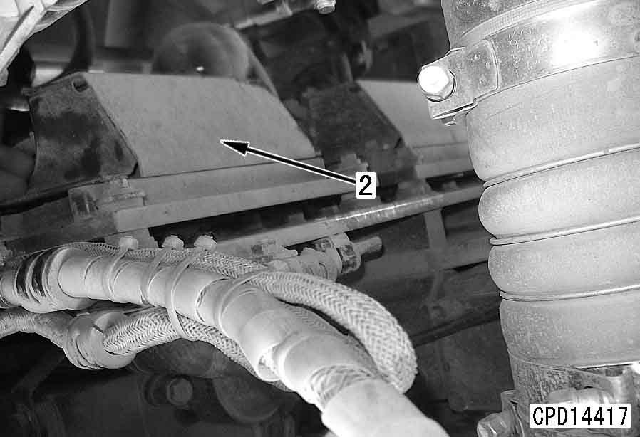
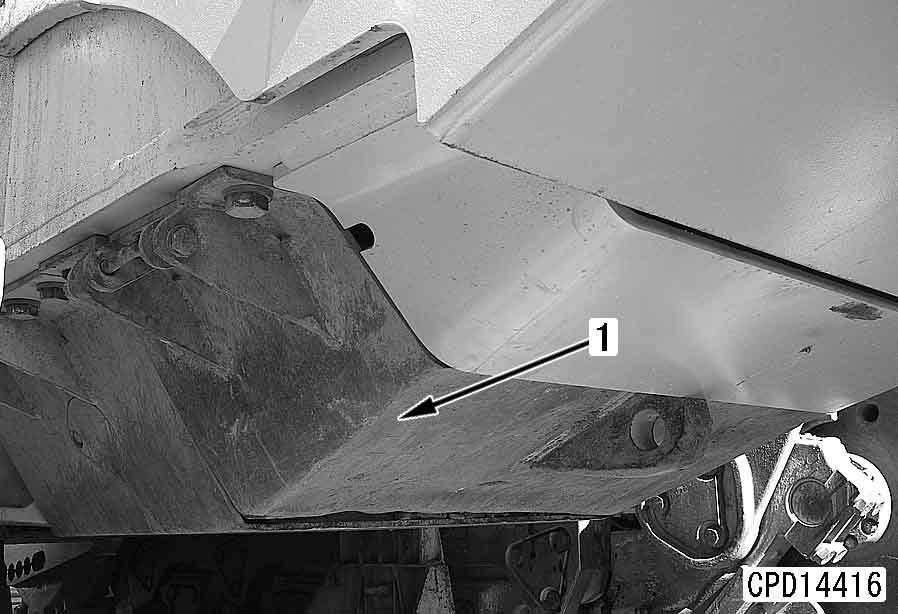
1.Remove engine underguard and power train underguard (front).
4 Engine underguard: 330 kg
4 Power train underguard (front): 340 kg a At the right track frame, disconnect 4 blade tilt cylinder hoses from the cover. a The front of the machine is raised using the blade, so install a blind plug securely in the hose at the tilt cylinder end.
2.Remove cover (1).
3.Remove seal (2) together with washer (3).[*1]
4.Remove washer (4), then remove spacer (5). a Oil will flow out from the pivot case, so catch it in an oil container.
6 Pivot case: 26 l a Repeat Steps 6 to 9 to remove the side pin on the opposite side.
5.Set stand and hydraulic jack [1] (294 kN {30 ton}) under radiator guard.
6.Remove cover (6).
7.Remove cover (7).
8.Remove main bolt (8) of side pin.
9.Using eyebolt [2], remove side pin (9). [*3] a It is difficult to remove the pin if the centers of the equalizer bar hole and track frame hole are not aligned, so use hydraulic jack [1] to adjust the height at the equalizer bar end before removing.
10.Operate hydraulic jack [1] slowly and lower chassis to point where equalizer bar contacts left and right track frames.
11.Disconnect lubrication tube (10).
12.Remove lock plate (11).[*4] k After removing the equalizer bar, do not lower the chassis.
14.Operate blade and raise front of chassis, and set hydraulic jack under radiator guard.
15.Raise equalizer bar (13), move it past main frame and track frame, and remove.
4 Equalizer bar assembly: 600 kg
13.Using tool N1, remove center pin (12).[*5] a It is difficult to remove the pin if the centers of the equalizer bar hole and main frame hole are not aligned, so use hydraulic jack [1] to adjust the height at the main frame end before removing.
Installation q Carry out installation in the reverse order to removal.
[*1] a After removing the grease from the pressfitting surface of the seal, coat with gasket sealant (LG-6). a Be careful not to install with the seal displaced in the direction of twisting.
[*2]
3 Main mounting bolt of side pin: 2,450 – 2,695 Nm {250 – 275 kgm} a After tightening main mounting bolts (8) of the side pin, tighten the mounting bolts of covers (6) and (7). a Take care of the tightening order of main mounting bolts (8) of the side pin and the mounting bolts of covers (6) and (7).
2 Inside surface of bushing: Grease (G2-LI) a Before installing the pin, operate hydraulic jack [1] to adjust the height of the main frame and align the center of the equalizer bar hole and track frame hole. a Set the pin with the grease hole facing the outside of the machine.
2 Lock plate mounting bolt: Tread tightener (LT-2)
3 Lock plate mounting bolt: 1,519 – 1,911 Nm {155 – 195 kgm}
2 Equalizer bar bushing and main frame bushing: Grease (G2-LI) a Before installing the pin, operate the crane to align the center of the main frame hole and the equalizer bar hole. q Refilling with oil (pivot case)
Add oil through oil filler to the specified level.
5 Pivot case: 26 l (SAE30)
Disassembly and assembly of equalizer bar bushing
Special tools
Disassembly
1.Center bushing Remove center bushings (1).
3)Set tool N2 in position and remove side bushing (4) from equalizer bar (5).
2.Side bushing
1)Remove seals (2).
2)Remove snap ring (3).
Assembly
1.Side bushing
1)Set side bushing (4) and tool N2 in position, then press fit side bushing (4) to equalizer bar (5).
2 Outer circumference of bushing: Anti-friction compound (LM-P) a Align the direction of installation of the side bushing as shown in the diagram below. a Side bushing press-fitting force: 47 – 96 kN {4.8 – 9.8 ton}
1]Make split surface (mating surface) (a) of outer bushing horizontal.
2]Set inner bushing and outer bushing grease hole (b) at an angle.
2.Center bushing
Using press, press fit bushing (1).
2 Outer circumference of center bushing: Anti-friction compound (LM-P) a Center bushing press-fitting force: 68.6 – 233.2 kN {7 – 23.8 ton} a After installing the snap ring, fill front and rear portion C of side bushing with grease (G2-LI).
2)Install snap ring (3).
2 Amount of grease to fill side bushing: 0.45 l
3)Using press, press fit seal (2). a Seal press-fitting force:
9.8 – 29.4 kN {1 – 3 ton} a Press fit so that the mouthpiece of the seal does not extend from the end face of the equalizer bar.
2 Lip of oil seal: Grease (G2-LI)
D475A-5E0
D475ASD-5E0
Hydraulic system
Removal and installation of hydraulic pump assembly 1
Removal k Lower the work equipment to the ground and stop the engine. Release the remaining pressure in the hydraulic piping. For details, see Testing and adjusting, "Releasing remaining pressure from hydraulic circuit". Then loosen the oil filler cap slowly to release the pressure inside the hydraulic tank. k Disconnect the cable from the negative (–) terminal of the battery.
1.Drain oil from hydraulic tank.
6 Hydraulic tank: 170 l
2.Remove floor frame assembly. For details, see "Removal of floor frame assembly".
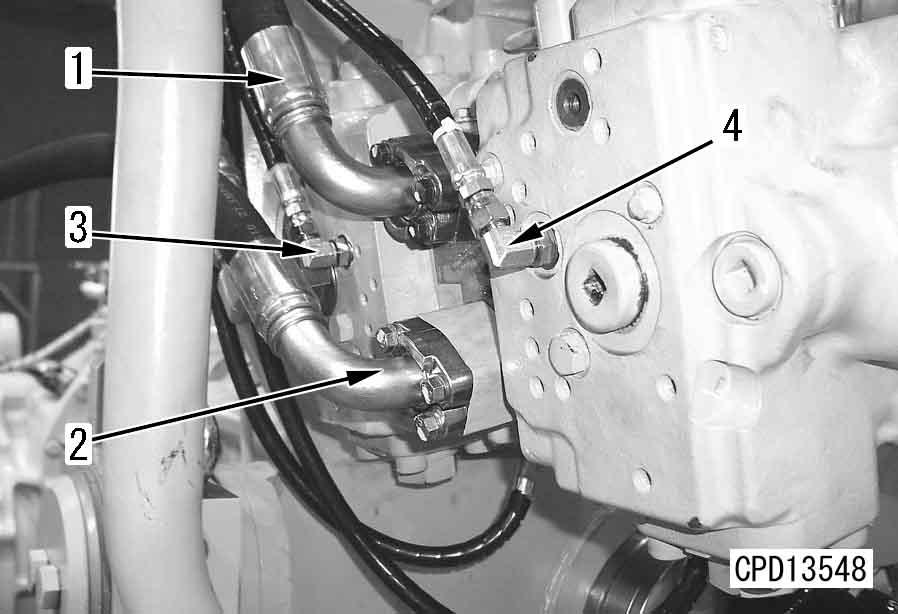
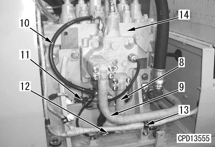
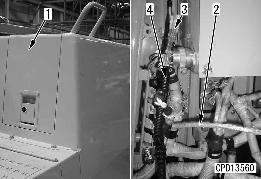
3.Disconnect pump outlet hoses (1) and (2).
4.Disconnect PPC hoses (3) and (4).
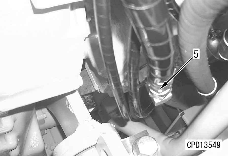
5.Disconnect hoses (5).
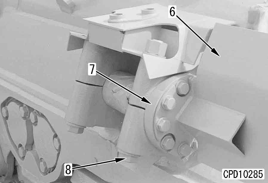
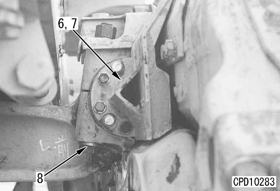
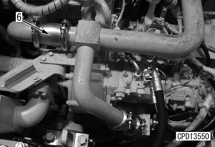
6.Remove tube coupling (6).
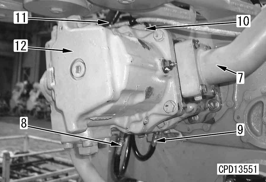
7.Remove pump inlet tube (7).
8.Disconnect PPC hoses (8) and (9).
9.Disconnect wiring clamp at the top of pump (10) and wiring harness connector (11).
10.Sling hydraulic assembly (12), then remove mounting bolts, and remove.
Installation q Carry out installation in the reverse order to removal. q Refilling with oil (hydraulic tank) Add oil through the oil filler to the specified level, and run the engine to circulate the oil through the system. Then check the oil level again.
D475A, D475ASD-5E0
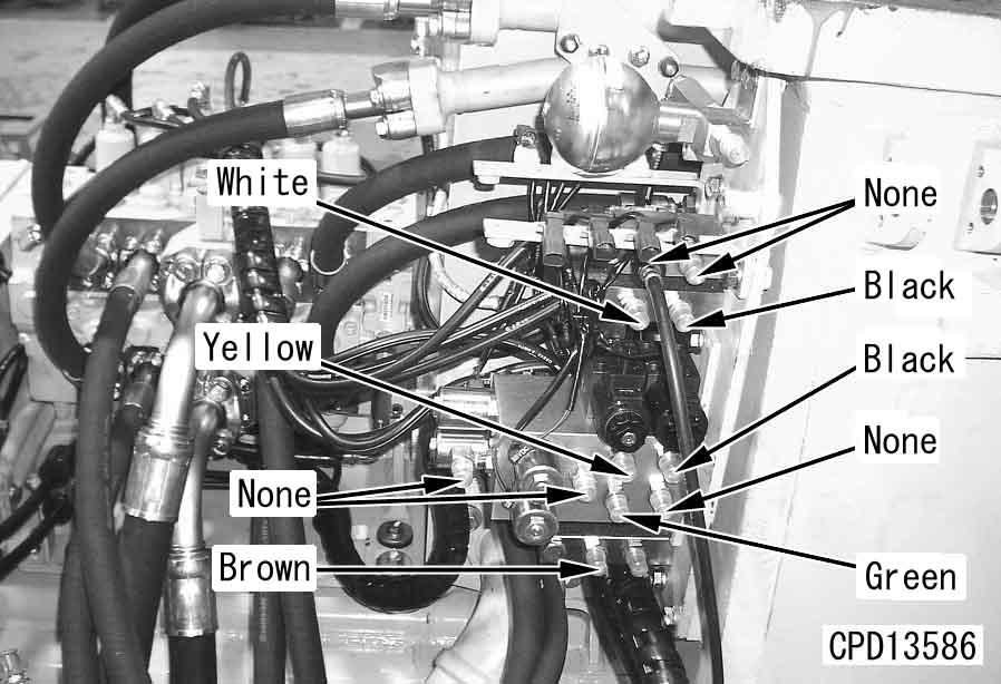
Removal and installation of hydraulic valve assembly
Removal k Lower the work equipment to the ground and stop the engine. Release the remaining pressure in the hydraulic piping. For details, see Testing and adjusting, "Releasing remaining pressure from hydraulic circuit". Then loosen the oil filler cap slowly to release the pressure inside the hydraulic tank. k Disconnect the cable from the negative (–) terminal of the battery.
1.Drain oil from hydraulic tank.
6 Hydraulic tank: 170 l
2.Remove right cover of operator cab.
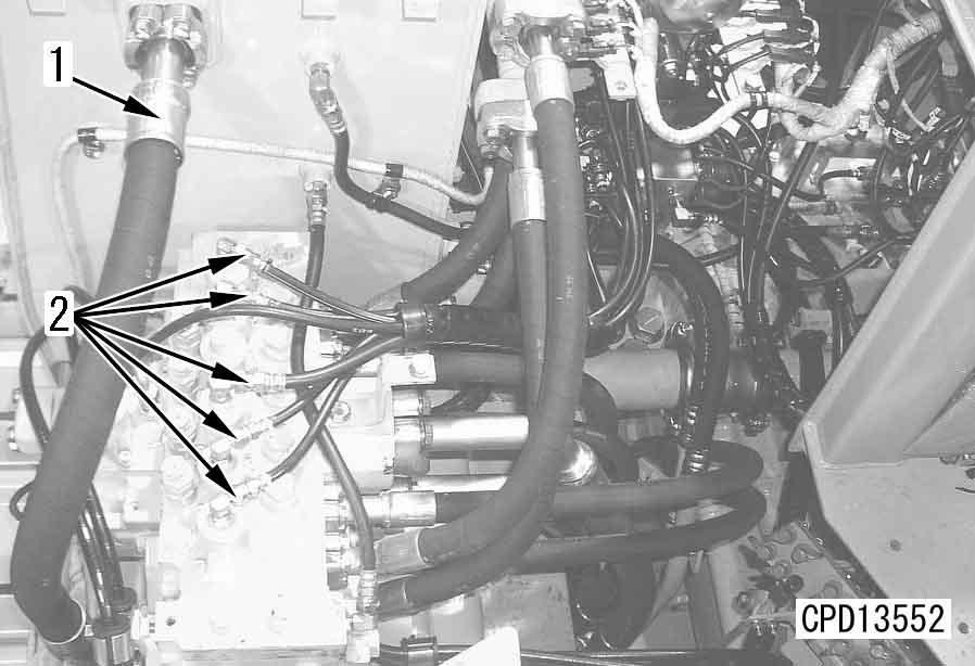
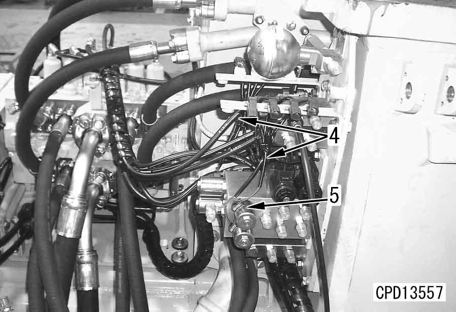
3.Remove hose (1).
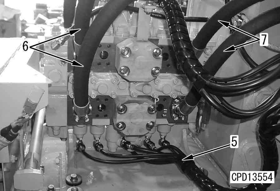
4.Disconnect 5 PPC hoses (2) from upper side.
6.Disconnect 5 PPC hoses (5) from bottom side. a PPC hoses are distinguished by color bands.
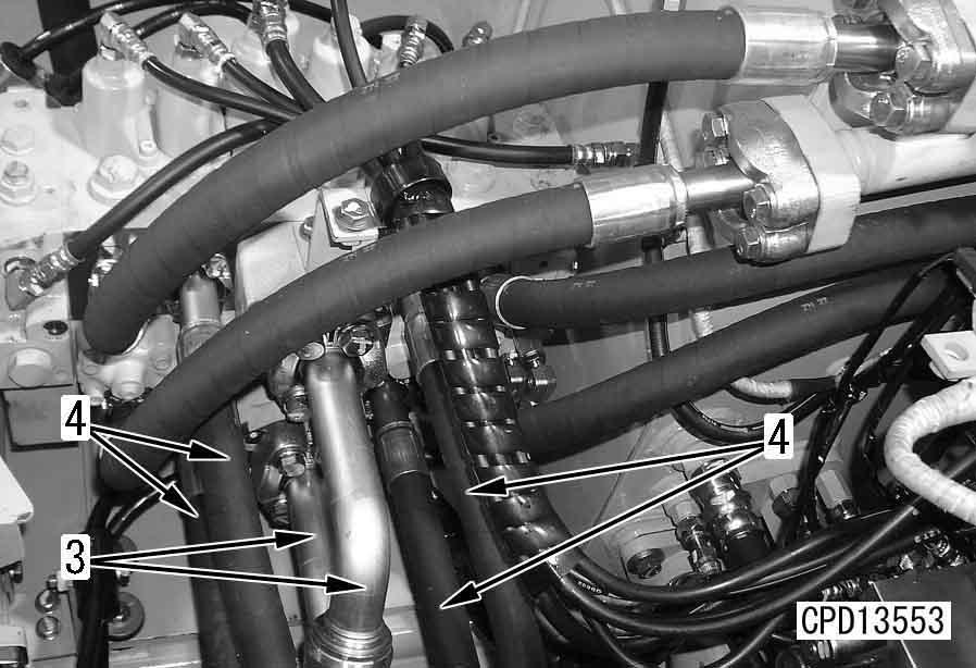
7.Disconnect ripper hoses (6) and (7).
5.Disconnect blade lift hoses (3) and blade tilt hoses (4).
8.Disconnect tubes (8) and (9).
9.Disconnect hose (10).
10.Disconnect wiring connectors (11) and (12), and clamp (13).
11.Sling control valve assembly (14), and then remove.
4 Main control valve assembly: 195 kg
Installation q Carry out installation in the reverse order to removal. q Refilling with oil (hydraulic tank) q Bleeding air in the hydraulic piping
Add oil through the oil filler to the specified level, and run the engine to circulate the oil through the system. Then check the oil level again.
For detail, see Testing and adjusting, Air bleeding from hydraulic cylinder.
Disassembly and assembly of control valve
Disassembly
1.Ripper lift valve a Do not disassemble spool assembly (2).
1)Remove case (1), spring (12), and retainer (9).
2)Remove lower case (1), spring (12), and retainer (9).
3)Remove spool (2).
2.Blade right tilt valve a Do not disassemble spool assembly (3).
1)Remove case (1), spring (15), and retainer (9).
2)Remove lower case (1), spring (15), and retainer (9).
3)Remove spool (3).
3.Blade lift valve a Do not disassemble spool assembly (4).
1)Remove case (3), loosen bolt (8), and remove retainer (7) and spring (6).
2)Remove plate (2), spring (13), and retainer (10).
3)Remove lower case (1), plate (2), spring (14), and retainer (11).
4)Remove spool (4).
4.Blade lift valve a Do not disassemble spool assembly (4).
1)Remove case (3), loosen bolt (8), and remove retainer (7) and spring (6).
2)Remove plate (2), spring (13), and retainer (10).
3)Remove lower case (1), plate (2), spring (14), and retainer (11).
4)Remove spool (4).
5.Blade left tilt valve a Do not disassemble spool assembly (3).
1)Remove case (1), spring (15), and retainer (9).
2)Remove lower case (1), spring (15), and retainer (9).
3)Remove spool (3).
6.Ripper tilt valve a Do not disassemble spool assembly (2).
1)Remove case (1), spring (12), and retainer (9).
2)Remove lower case (1), spring (12), and retainer (9).
3)Remove spool (2).
Assembly
q Coat the sliding surface of each part with engine oil before installing.
1.Ripper tilt valve
1)Install spool (2) to the valve body.
2)Install lower retainer (9) and spring (12). Fit the O-ring to case (1) and install them.
3)Install retainer (9) and spring (12). Fit the O-ring to case (1) and install them.
3 Case mounting bolt:
27.5 – 34.3 Nm {2.8 – 3.5 kgm}
2.Blade left tilt valve
1)Install spool (3) to the valve body.
2)Install lower retainer (9) and spring (15). Fit the O-ring to case (1) and install them.
3)Install retainer (9) and spring (15). Fit the O-ring to case (1) and install them.
3 Case mounting bolt: 27.5 – 34.3 Nm {2.8 – 3.5 kgm}
3.Blade lift valve
1)Install spool (4) to the valve body.
2)Install lower retainer (11), spring (14), and plate (2). Fit the O-ring to case (1) and install them.
3)Install retainer (10), spring (13), and plate (2).
4)Install spring (6) and retainer (7) to case (3) and secure them with bolt (8). Fit the O-ring to case (3) and install them.
3 Retainer mounting bolt:
11.8 – 14.6 Nm {1.2 – 1.5 kgm}
3 Case mounting bolt:
27.5 – 34.3 Nm {2.8 – 3.5 kgm}
4.Blade lift valve
1)Install spool (4) to the valve body.
2)Install lower retainer (11), spring (14), and plate (2). Fit the O-ring to case (1) and install them.
3)Install retainer (10), spring (13), and plate (2).
4)Install spring (6) and retainer (7) to case (3) and secure them with bolt (8). Fit the O-ring to case (3) and install them.
3 Retainer mounting bolt:
11.8 – 14.6 Nm {1.2 – 1.5 kgm}
3 Case mounting bolt:
27.5 – 34.3 Nm {2.8 – 3.5 kgm}
5.Blade right tilt valve
1)Install spool (3) to the valve body.
2)Install lower retainer (9) and spring (15). Fit the O-ring to case (1) and install them.
3)Install retainer (9) and spring (15). Fit the O-ring to case (1) and install them.
3 Case mounting bolt: 27.5 – 34.3 Nm {2.8 – 3.5 kgm}
6.Ripper lift valve
1)Install spool (2) to the valve body.
2)Install lower retainer (9) and spring (12). Fit the O-ring to case (1) and install them.
3)Install retainer (9) and spring (12). Fit the O-ring to case (1) and install them.
3 Case mounting bolt: 27.5 – 34.3 Nm {2.8 – 3.5 kgm}
Disassembly
Disassembly
1.Remove case (7) from valve body (1). Loosen bolt (6) and remove retainer (8), spring (5), retainer (4), plug (3), and spool (2).
2.Remove plug (14), spring (12), and spool (11).
3.Remove plug (18), spring (17), and spool (16).
4.Remove plug (33), spring (32), and spool (31) from block (30).
5.Remove valve assembly (20) from block (30).
6.Remove seat (35), spring (36), and ball (37) from block (30). a After disassembling, if any of body (1) and spools (2), (11), and (16) is defective, replace the whole me rge divider valve assembly.
Assembly
q Coat the sliding surface of each part with engine oil before installing.
1.Fit the O-ring and install ball (37), spring (36), and seat (35) to block (30).
3 Seat: 9.8 – 12.7 Nm {1.0 – 1.3 kgm}
2.Fit the O-ring and install valve assembly (20) to block (30).
3 Valve assembly: 24.5 – 34.3 Nm {2.5 – 3.5 kgm}
3.Install spool (31) and spring (32). Fit the O-ring and install plug (33).
3 Plug assembly: 19.6 – 24.5 Nm {2 – 2.5 kgm}
4.Install spool (16) and spring (17). Fit the O-ring to plug (18) and install them to valve body (1).
3 Plug assembly: 147.1 – 186.3 Nm {15 – 19 kgm}
5.Install spring (12) to spool (11). Fit the O-ring to plug (14) and install them.
3 Plug assembly: 147.1 – 186.3 Nm {15 – 19 kgm}
6.Install retainer (4), spring (5), retainer (8), and plug (3) to spool (2) and install them to body (1). Fit the O-ring and install case (7).
3 Mounting bolt of case (7): 27.5 – 34.3 Nm {2.8 – 3.5 kgm}
Removal and installation of PPC relief valve assembly
Removal k Lower the work equipment to the ground and stop the engine. Release the remaining pressure in the hydraulic piping. For details, see Testing and adjusting, Releasing remaining pressure from hydraulic circuit.
Then loosen the oil filler cap slowly to release the pressure inside the hydraulic tank.
1.Remove operator’s cab right cover.
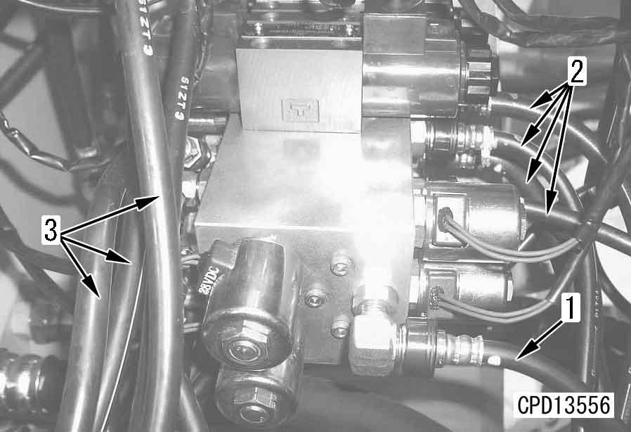
2.Remove hoses (1), (2), and (3).
3.Disconnect connector (4).
4.Remove PPC relief valve assembly (5).
Installation q Carry out installation in the reverse order to removal.
Disassembly and assembly of hydraulic cylinder assembly
Special tools
1790-502-1003 Cylinder repair stand
790-201-1702Push tool kit t 1
790-201-1881•Push tool1
790-201-1871•Push tool1
Disassembly
1.Cylinder tube Remove cylinder tube.
2.Quick drop valve assembly a Blade lift cylinder only.
1)Remove quick drop valve assembly (1).
2
790-201-1721•Push tool1
790-101-5021•Grid1
790-201-1500Push tool kit t 1
790-201-1670•Plate1
790-201-1680•Plate1
790-201-1690•Plate1
01010-50816•Bolt1 3
790-201-1530•Plate1
790-101-5021•Grip1 01010-50816•Bolt1
2)Disassemble quick drop valve assembly as follows.
1]Remove elbow (2).
2]Remove spring (3), washer (4), and valves (5) and (6), and pull out collar (7).
1)Set cylinder assembly (8) to tool U1
2)Remove head assembly (9).
3)Pull out piston rod assembly (10). a Put an oil container under the cylinder to catch the oil.
6)Disassemble piston assembly as follows.
1]Remove wear ring (17).
2]Remove piston ring (18).
1)Set piston rod assembly (10) to tool U1
5.Head assembly
1)Remove head assembly (19) from piston rod.
2)Remove spacer (11).
3)Remove piston assembly (12).
4)Remove backup rings (13) and (14), and O-ring (15).
5)Remove retainer (16).
2)Disassemble head assembly as follows.
1]Remove O-ring (20) and backup ring (21).
2]Remove snap ring (22), then remove seal (23).
3]Remove packing (24), then remove bushing (25).
Assembly a Coat the sliding surfaces of all parts with engine oil before insta lling. Be careful not to damage the packings, dust seals, and O-rings when installing.
1.Head assembly
1)Assemble head assembly as follows.
1]Using tool U2, press fit bushing (25) to head.
2]Install packing (24).
3]Using tool U3, press fit seal (23).
4]Install snap ring (22).
2)Install head assembly (19) to piston rod.
2.Piston assembly
1)Assemble piston assembly as follows.
1]Using tool U4, expand piston ring (18).
a Set the piston ring on the expander and turn the handle 8 –10 times to expand the ring.
2]Remove piston ring (18) from tool U4, then install to piston.
3]Set tool U5 in position and compress piston ring (18).
4]Install wear ring (17) to piston.
2)Install retainer (16).
3)Install O-ring (15) and backup rings (14) and (13).
a Coat the O-ring and backup ring portion with grease, and secure the backup ring to prevent it from opening.
4)Install piston assembly (12).
5)Assemble spacer (11) and tighten mounting bolts.
2 Mounting bolt: Thread tightener (LT-2)
3 Mounting bolt: Blade lift: 98 – 123 Nm {10 – 12.5 kgm}
Blade lift, ripper lift, ripper tilt: 157 – 196 Nm {16 – 20 kgm}
3.Piston rod assembly
1)Set cylinder (8) to tool U1 a Push in the piston rod fully.
2)Assemble piston rod (10) to cylinder (8). a Coat the seal portion of the piston with grease.
3)Push head assembly to cylinder and tighten mounting bolts. a Coat the backup ring with grease.
3 Mounting bolt:
Blade lift: 490 ± 49 Nm {50 ± 5 kgm}
Blade tilt, ripper lift, ripper tilt: 1,320 ± 140 Nm {135 ± 15 kgm}
2)Install quick drop valve assembly (1).
4.Quick drop valve assembly a Blade lift cylinder only.
1)Assemble quick drop valve assembly as follows.
1]Assemble collar (7), and install valves (6) and (5), washer (4), and spring (3).
2]Install elbow (2).
5.Cylinder tube
Install cylinder tube.
Disassembly and assembly of ripper pin puller cylinder assembly
Special tools
1790-502-1003 Cylinder repair stand q 1
790-201-1702Push tool kit t 1
790-201-1881•Push tool1
790-201-1871•Push tool1
790-201-1721•Push tool1
790-101-5021•Grid1
01010-50816•Bolt1
790-201-1500Push tool kit t 1
790-201-1670•Plate1
790-201-1680•Plate1
790-201-1690•Plate1
790-201-1530•Plate1
790-101-5021•Grip1 a Put an oil container under the cylinder to catch the oil.
Disassembly
1.Cylinder assembly
1)Set pin puller cylinder assembly (1) to tool U1
2)Using tool U6, loosen cylinder head assembly (2).
3)Remove piston rod (3) together with cylinder head assembly (2).
2.Cylinder head assembly
1)Remove cylinder head assembly (2) from piston rod (3).
2)Remove O-ring (5) and backup ring (6).
3)Remove O-ring (7).
4)Remove snap ring (8), then remove dust seal (9).
5)Remove rod packing (10), then remove bushing (11).
Remove piston ring (12) from piston rod (3).
1)Using tool U2, press fit bushing (11) to cylinder head (4).
Assembly a Coat the sliding surfaces of all parts with engine oil before insta lling. Be careful not to damage the packings, dust seals, and O-rings when installing.
1)Using tool U4, expand piston ring (12). a Set the piston ring on the expander and turn the handle 8 – 10 time to expand the ring.
2)Remove piston ring (12) from tool, then install to piston rod (3).
3)Using tool U5, compress piston ring (12).
2)Using tool U3, press fit dust seal (9) to cylinder head (4).
3)Install snap ring (8) and rod packing (10).
4)Install O-ring (7).
5)Install backup ring (6) and O-ring (4).
3.Cylinder assembly
1)Set cylinder to tool U1 and support with block [1].
2)Install piston rod (3) together with cylinder head assembly (2).
a Coat the seal portion of the piston with grease.
a Coat the backup ring with grease.
a Push in the piston fully.
3)Using tool U6, tighten cylinder head assembly (2).
3 Cylinder head assembly: 441 ± 44.1 Nm {45 ± 4.5 kgm}
6)Install cylinder head assembly (2) to piston rod (3).
D475A-5E0
D475ASD-5E0
D475A-5E030001
Work equipment
Removal and installation of blade assembly 1
Removal k Lower the work equipment to the ground in a horizontal place, and set blocks [1] securely under the left and right straight frames. k Release the remaining pressure from the hydraulic circuit. For details, see Testing and adjusting, "Releasing remaining pressure from hydraulic circuit". Then loosen the oil filler cap slowly to release the pressure inside the hydraulic tank.
3.Remove left and right covers (4).
4.Disconnect hoses (5). a Mark the hoses before disconnecting. a Fit blind plugs to prevent dirt or dust from entering the piping.
5.Remove left and right trunnion caps (6).
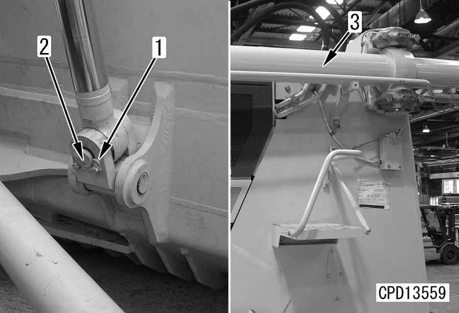
1.Remove lock plate (1) of lift cylinder rod pin and extract pin (2). [*1] q Repeat the same procedure to disconnect the cylinder from the blade on the opposite side.
2.Sling lift cylinder assembly (3), then start engine and retract piston rod fully, fit cylinder lock tool and secure to radiator guard. a Tie the piston rod with wire to prevent it from coming out.
6.Remove blade assembly (7). a Start the engine, drive the machine slowly in reverse, and disconnect the blade assembly from the trunnions.
Installation q Carry out installation in the reverse order to removal.
[*1] a Adjust with block [1] so that height (b) and width (c) of the left and right straight frames are the dimensions given below. q Height (b) of trunnion portion: Approx. 981 mm q Brace width (c): Approx. 3,840 mm q Refilling with oil (hydraulic tank)
Add oil through oil filler to the specified level. Run the engine to circulate the oil through the system. Then check the oil level again.
D475A, D475ASD-5E0
Disassembly and assembly of giant ripper assembly
Disassembly k Lock the brake securely.
1.Mount machine on block [1] and lower blade to ground.
2.Sling shank, then operate pin-puller switch and pull out shank pin.
3.Raise ripper fully, and lower shank (1) to remove.
4 Shank: 1,050 kg
4.Set stand [2] under arm and beam.
7.Disconnect 4 lift cylinder hoses (4), 4 tilt cylinder hoses (5), and 2 pin-puller cylinder hoses (6).
5.Sling lift cylinder assembly and remove pin (2). a Start the engine, retract the piston rod fully, and lower on top of the arm.
6.Sling lift cylinder assembly and remove pin (3). a Start the engine, retract the piston rod fully, and lower on top of the lift cylinder. k Release the remaining pressure from the hydraulic circuit. For details, see Testing and adjusting, "Releasing remaining pressure from hydraulic circuit".
8.Sling tilt cylinder assembly (7), then remove pin (8) and lift off tilt cylinder assembly (7).
4 Tilt cylinder assembly: 410 kg
9.Sling lift cylinder assembly (9), then remove pin (10) and lift off lift cylinder assembly (9).
4 Lift cylinder assembly: 400 kg
10.Sling beam (11), then remove left and right pins (12) and lift off beam (11).
4 Beam: 2,450 kg
2.Sling beam (11) and set in mounting position, then fit left and right pins (12) and secure with lock plate.
4 Arm: 2,450 kg a Set a stand under the beam.
11.Sling arm (13), then remove left and right pins (14) and lift off arm (13).
4 Arm: 1,800 kg
3.Sling lift cylinder assembly (9) and set in mounting position, then fit pin (10) and secure with lock plate.
4 Lift cylinder assembly: 400 kg
Assembly
1.Sling arm (13) and set in mounting position, then fit left and right pins (14) and secure with lock plate.
4 Arm: 1,800 kg a Set a stand under the arm.
4.Sling tilt cylinder assembly (7) and set in mounting position, then fit pin (8) and secure with lock plate.
4 Tilt cylinder assembly: 410 kg
D475A, D475ASD-5E0
5.Connect 2 pin-puller cylinder hoses (6), 4 tilt cylinder hoses (5), and 4 lift cylinder hoses (4).
8.Mount machine on block [1] and lower blade to ground. k Lock the brake securely.
9.Operate ripper and raise slightly to remove stand [2].
10.Raise ripper fully, pass wire through shank holder, then raise shank (1) slowly, align with pin hole, and operate pin-puller switch to insert shank pin.
11.Raise blade and lower machine from block [1].
6.Sling tilt cylinder assembly, start engine, extend piston rod and align with pin hole, then install pin (3) and secure with lock plate.
7.Sling lift cylinder assembly, start engine, extend piston rod and align with pin hole, then install pin (2) and secure with lock plate.
12.Bleed air from cylinder. For details, see Testing and adjusting, "Bleed air from hydraulic cylinder".
Cab and its attachments
Removal and installation of ROPS guard
Removal
1
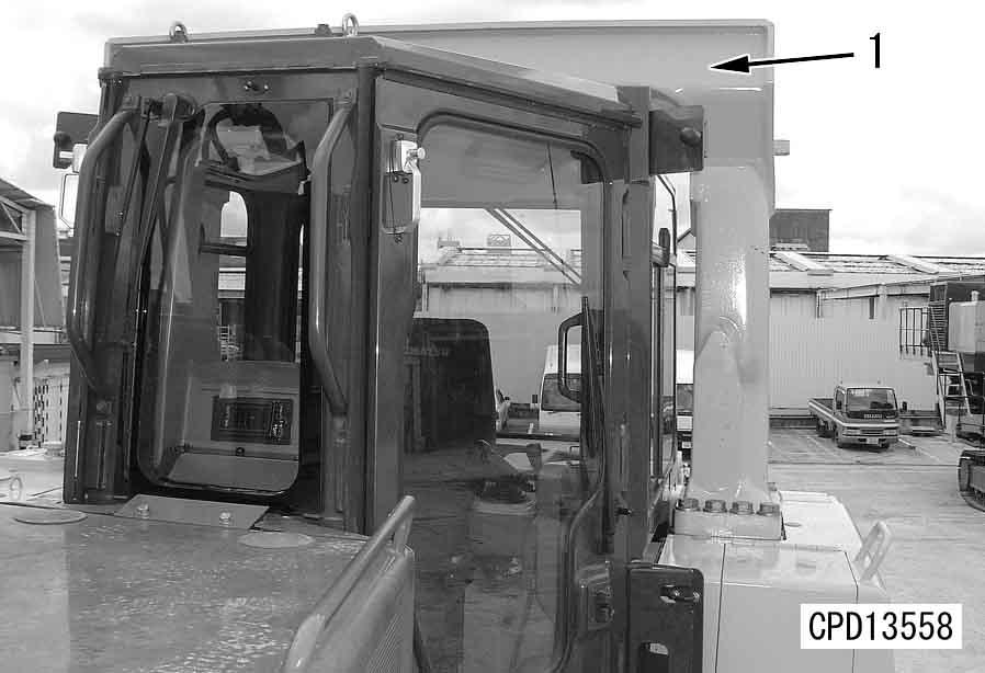
1.Sling ROPS guard (1) and remove 16 mounting bolts (2).[*1]
2.Lift off ROPS guard (1).
4 ROPS guard: 918 kg
Installation q Carry out installation in the reverse order to removal.
3 ROPS guard mounting bolt:
1,960 – 2,450 Nm {200 – 250 kgm}
Removal and installation of operator’s cab assembly
Removal k Disconnect the cable from the negative (–) terminal of the battery.
1.Remove ROPS guard. For details, see Removal of ROPS guard.

2.Remove left cover (1) of operator’s cab.
3.Disconnect wiring connectors (12V, 21 and 20) (2).
4.Disconnect 4 washer hoses (3) and 19 washer wires (4).
Washer hose
Red:Right doorBlack:Rear window
Blue:Left door –:Front window
6.Remove front covers (8), (9) and (10).
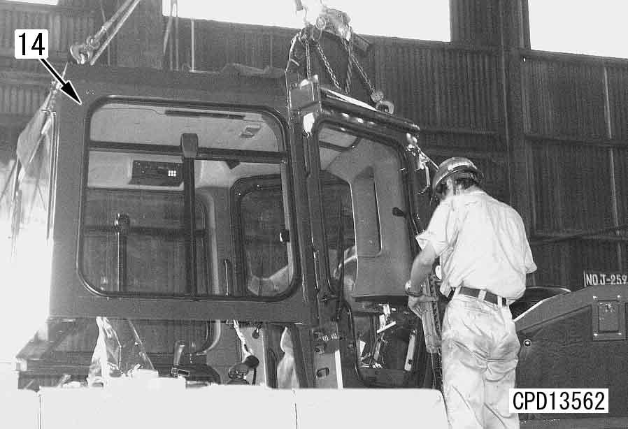
7.Remove 3 mounting bolts (11), 6 bolts (12) and 15 bolts (13).
8.Sling operator’s cab assembly (14), then remove.
4 Operator’s assembly: 500 kg
Installation q Carry out installation in the reverse order to removal.
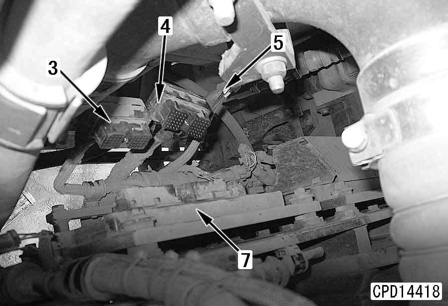
Removal and installation of floor frame assembly
Special tools
4.Remove sidecover (5).
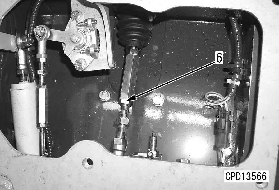
5.Disconnect brake pedal linkage (6).[*4] a Check the mounting dimensions of brake rod before disconnection.
Removal
1.Remove operator’s cab assembly. For details, see "Removal of operator’s cab assembly".
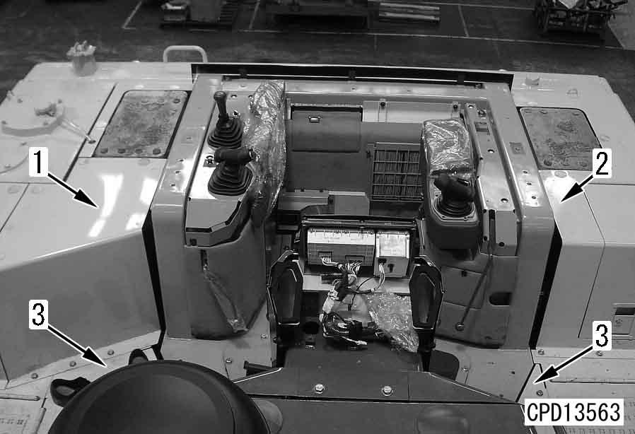
2.Remove covers (1), (2) and (3).
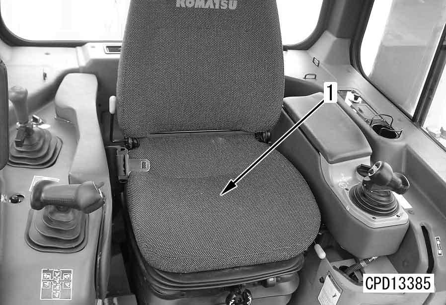
3.Lift off operator's seat (4). a Remove the seat together with the undercover.
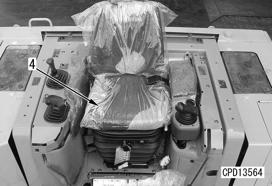
4 Operator’s seat: 64 kg
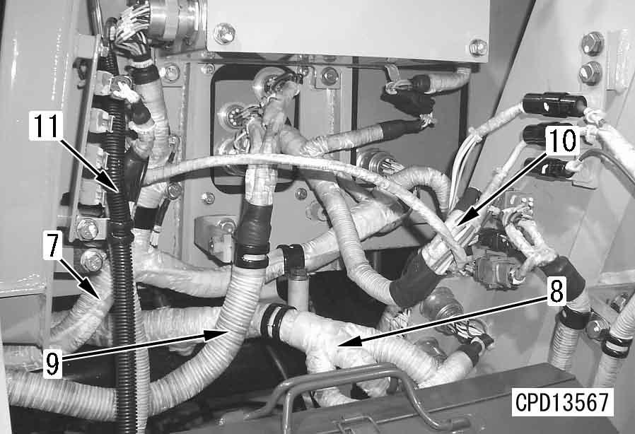
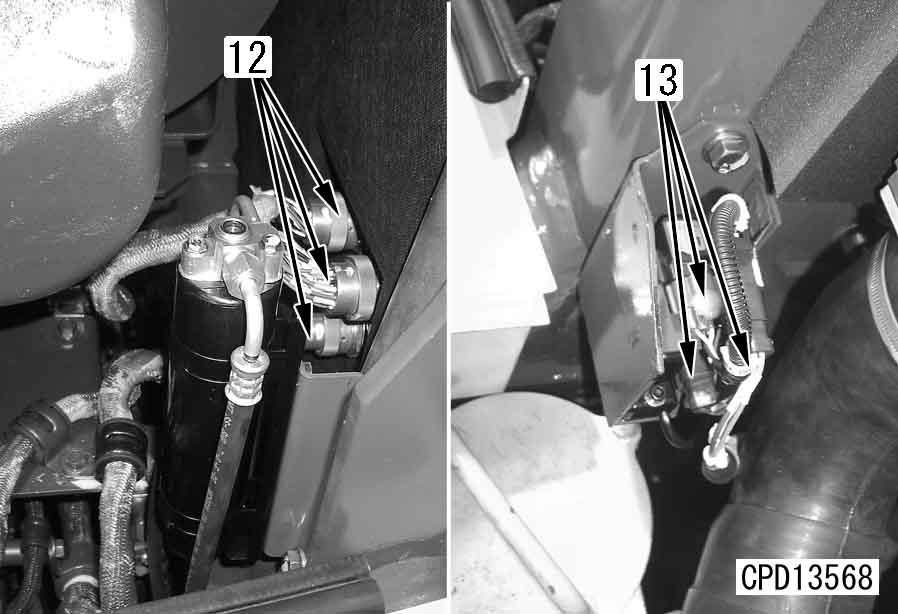
6.Disconnect wiring harness connectors (7) (VF1-CA1-VF2), (8) (PL1-PL2-PL3), (9) (FD5BWR1-PWR2-USB-12V-20-21), and (10) (TCIV12-BSW), and then disconnect the wiring clamp. Disconnect washer hose (11) and the clamp.
7.Remove wiring connector (12) (CN2-SSA-PT1) and the clamp.
8.Disconnect wiring connector (13) (995-111VFD) and remove the connector bracket.
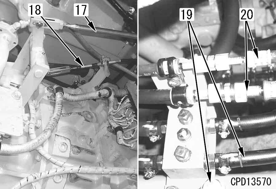
11.Remove brake rod (17).
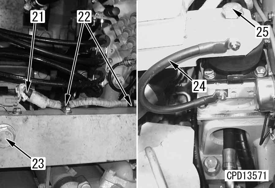
12.Disconnect parking brake cable (18).[*3]
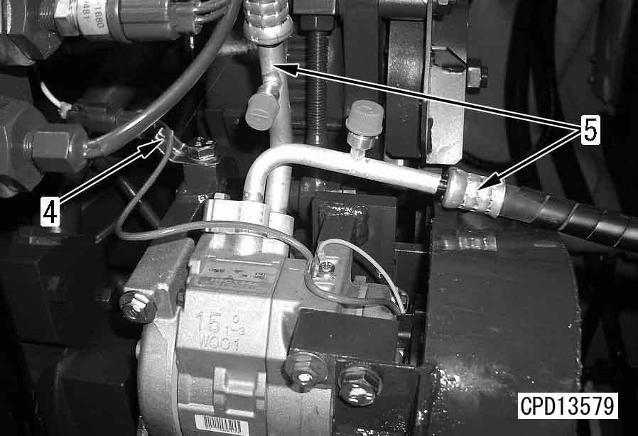
13.Disconnect air conditioner hose (19).[*1] a Collect the refrigerant (R134a) from the air conditioner circuit.
14.Disconnect heater hose (20).
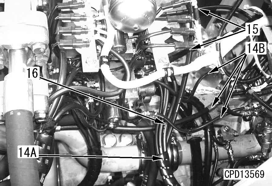
9.Disconnect blade PPC hose (14A), hose (14B) and ripper PPC hose (15).[*2]
10.Disconnect wiring connector and clamp (16).
15.Disconnect wiring connector (21) and clamp (22).
16.Remove floor frame bracket bolt (23) on right side.
17.Disconnect ground wiring (24).
18.Remove floor frame bracket bolt (25) on left side.
D475A, D475ASD-5E0
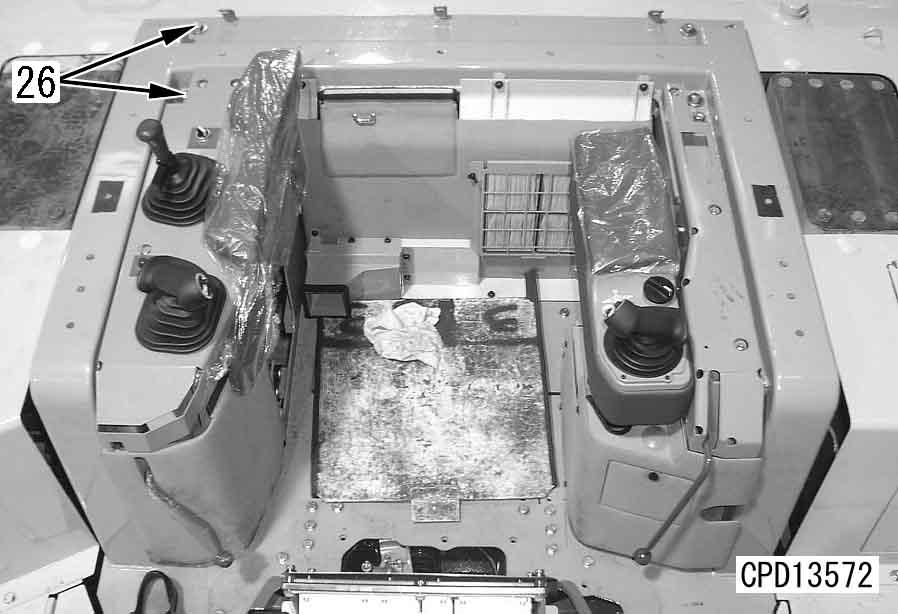
19.Remove 8 floor frame rear mounting bolts (26).
Installation q Carry out installation in the reverse order to removal.
[*1] a Install the hoses without twisting or interference. a Install the air conditioner circuit hoses carefully to prevent dirt, dust, or water from getting inside the hoses. a Check that there are O-rings at the piping connection of the air conditioner hoses before installing. Coat the O-rings thoroughly with compressor oil (Shell Suniso 4G or 5G).
20.Lift off floor frame assembly (27).
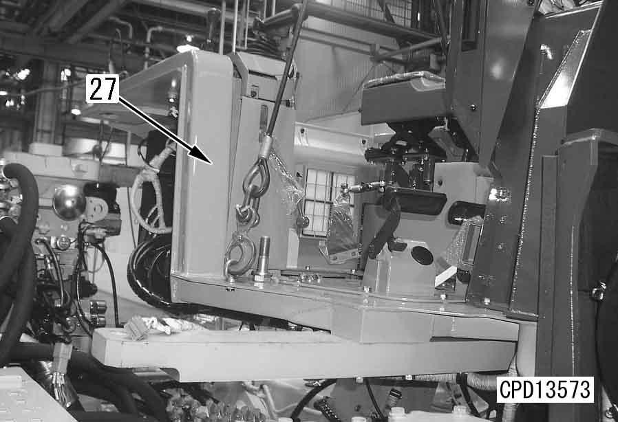
4 Floor frame assembly: 500 kg a Use a chain block to adjust the balance in all directions (front, rear, left, and right), and lift off slowly.
3 Tighten the air conditioner gas piping to the following tightening torques.
[*2] a The connecting positions of the PPC hoses are indicated by the band colors on their quick couplers. When connecting them, confirm them by the band colors.
[*3] a Adjust installed length of parking brake cable. For details, see Testing and adjusting, Adjusting brake pedal and parking brake lever.
[*4] a Adjust installed length of brake rod. For details, see Testing and adjusting, "Adjusting brake pedal and parking brake lever".
3 Brake pedal linkage turnbuckle: 34.3 – 58.8 Nm {3.5 – 6 kgm} q Charging with air conditioner gas q Refilling with coolant
Using tool X, charge the air conditioner circuit with air conditioner gas (R134a).
Add coolant to the specified level, and run the engine to circulate the coolant through the system. Then check the coolant level again.
Electrical system
Removal and installation of controller assembly 1
Removal k Disconnect the cable from the negative (–) terminal of the battery.
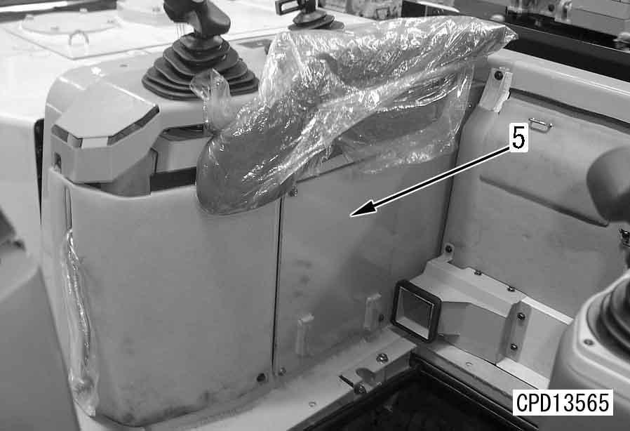
1.Remove cover (1).
2.Remove services switch (2) and connector bracket (3).
3.Remove 2 clips for wiring harness (5).
4.Remove 3 brackets (4).
5.Disconnect wiring connectors of engine controller (6). (CN-LE1, CN-LE32, CN-LE31, CN-LE4, CNLE2, CN-LE52, CN-LE51)
6.Remove engine controller (6).
7.Remove engine controller mounting bracket (7).
8.Disconnect wiring connectors of transmission controller (8). (CN-TMCN1, CN-TMCN2, CN-TMCN3)
9.Remove transmission controller (8).
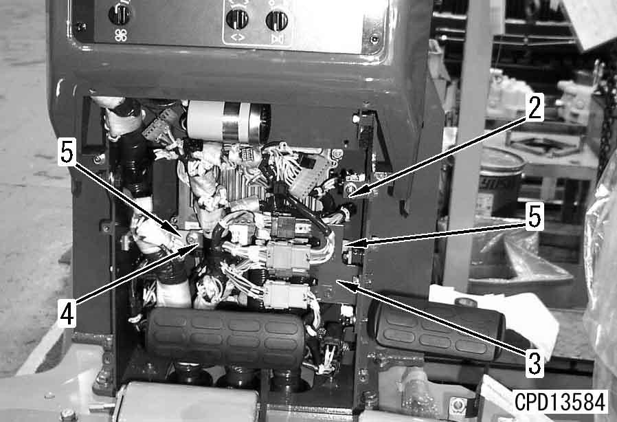
10.Disconnect wiring connectors of steering controller (9). (CN-STCN1, CN-STCN2, CNSTCN3)
11.Remove steering controller (9).
Installation q Carry out installation in the reverse order to removal.
Removal and installation of engine controller assembly (left) 1
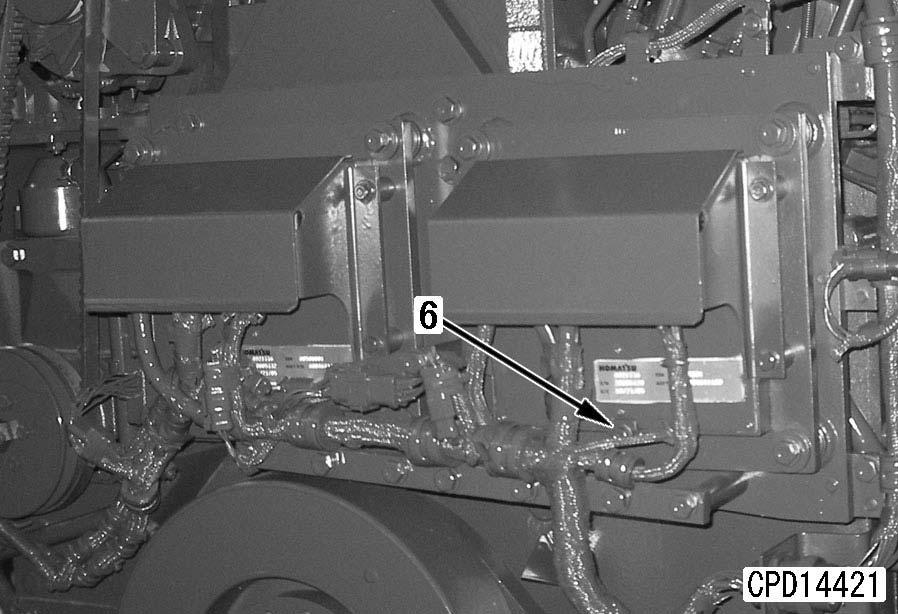
Removal k Disconnect the cable from the negative (–) terminal of the battery. a Remove the fan motor piping clamps to make a space for work. a The cover mounting bolts are used to fix the controller, too.
1.Remove undercover (1).
3.Disconnect wirings (3), (4) and (5).
2.Remove the 4 controller cover mounting bolts and remove cover (2).
4.Remove ground cable fixing bolt (6) and controller (7).
D475A, D475ASD-5E0
5.Remove the right controller similarly to the left one.
Installation q Carry out installation in the reverse order to removal.
Removal and installation of air conditioner condenser assembly
Special tools
Removal
1.Open engine right side cover (1) and remove side covers (2) and (3).
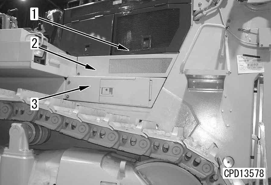
3.Remove air conditioner condenser assembly (5) from right side of chassis.
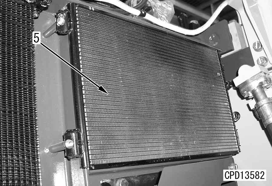
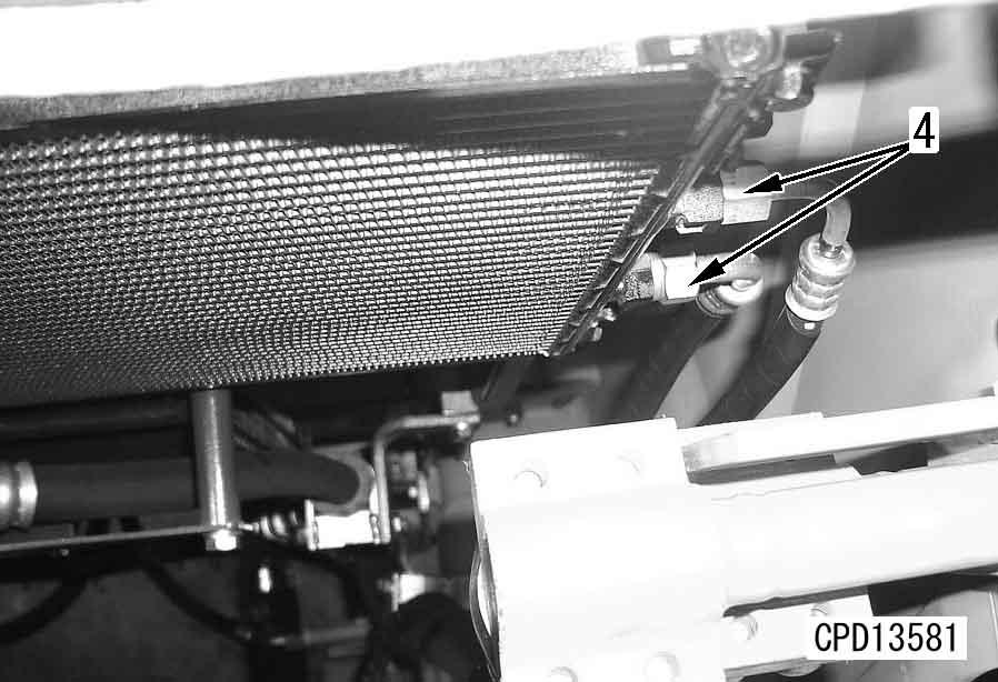
2.Disconnect hoses (4).[*1]
Installation q Carry out installation in the reverse order to removal.
[*1] a Install the air conditioner circuit hoses carefully to prevent dirt, dust, or water from getting inside the hoses. a Check that there are O-rings at the piping connection of the air conditioner hoses before installing. Coat the O-rings thoroughly with compressor oil (Shell Suniso 4G or 5G).
3 Air conditioner hose sleeve nut:
Outside: 22.05 ± 2.45 Nm {2.25 ± 0.25 kgm}
Inside: 13.25 ± 1.47 Nm {1.35 ± 0.15 kgm} q Charging with air conditioner gas a Collect the refrigerant (R134a) from the air conditioner circuit. a Fit blind plugs to prevent dirt or moisture from entering the hoses. a Be careful not to damage or drop the Orings.
Using tool X, charge the air conditioner circuit with air conditioner gas (R134a).
Removal and installation of air conditioner compressor assembly
Special tools
Removal k Disconnect the cable from the negative (–) terminal of the battery
1.Open engine right side cover (1) and remove side covers (2) and (3).
2.Disconnect air conditioner compressor clutch connector (CN-351) (4).
3.Disconnect 2 compressor hoses (5).[*1] a Collect the refrigerant (R134a) from the air conditioner circuit. a Fit blind plugs to prevent dirt or moisture from entering the hoses. a Be careful not to damage or drop the Orings.
D475A, D475ASD-5E0
4.Loosen 4 mount bolts (6).
5.Loosen locknut, and remove adjustment bolt (7), then remove belt from pulley.[*2]
6.Remove 4 mount bolts (6), then remove air conditioner compressor assembly (8).
Installation q Carry out installation in the reverse order to removal.
[*1] a Install the air conditioner circuit hoses carefully to prevent dirt, dust, or water from getting inside the hoses. a Check that there are O-rings at the piping connection of the ai r conditioner hoses before installing.
Coat the O-rings thoroughly with compressor oil (Shell Suniso 4G or 5G).
3 Air conditioner hose mounting bolt: 10 ± 2 Nm {1.0 ± 0.2 kgm}
[*2] a Adjust the belt tension. For details, see Testing and adjusting, "Testing and adjusting tension of air conditioner compressor belt". q Charging with air conditioner gas Using tool X, charge the air conditioner circuit with air conditioner gas (R134a).
Removal and installation of air conditioner unit
Special tools
Removal
1.Remove operator's seat (1).
6.Disconnect air hose (7).
2.Remove fresh air filter (2).
3.Remove cover (3).
4.Remove duct (4).
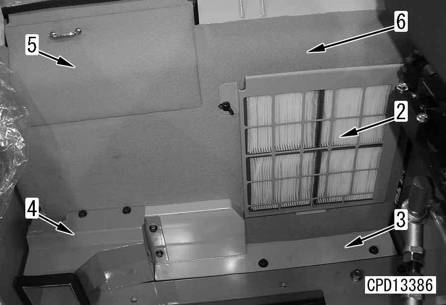
5.Remove garnishes (5) and (6).
7.Remove fresh air filter bracket (8).
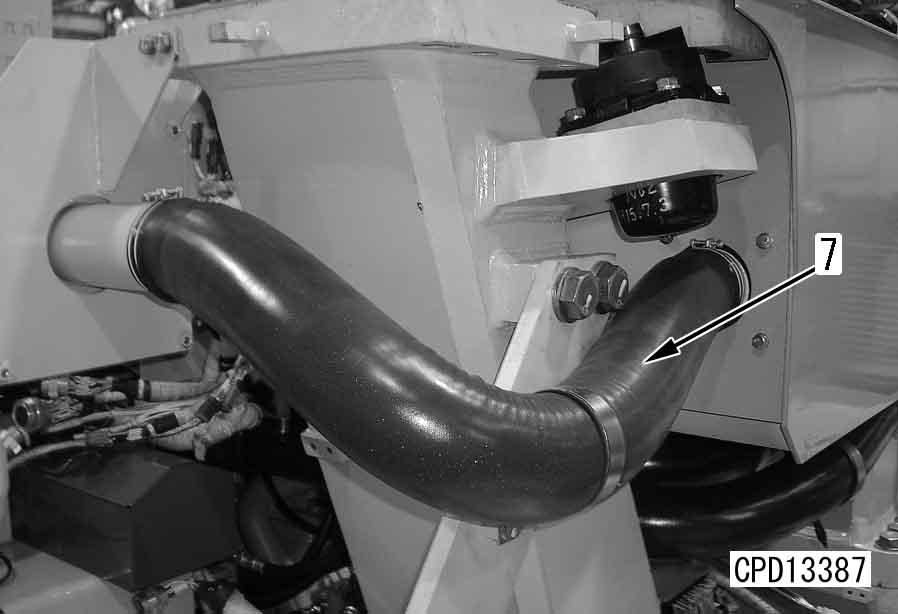
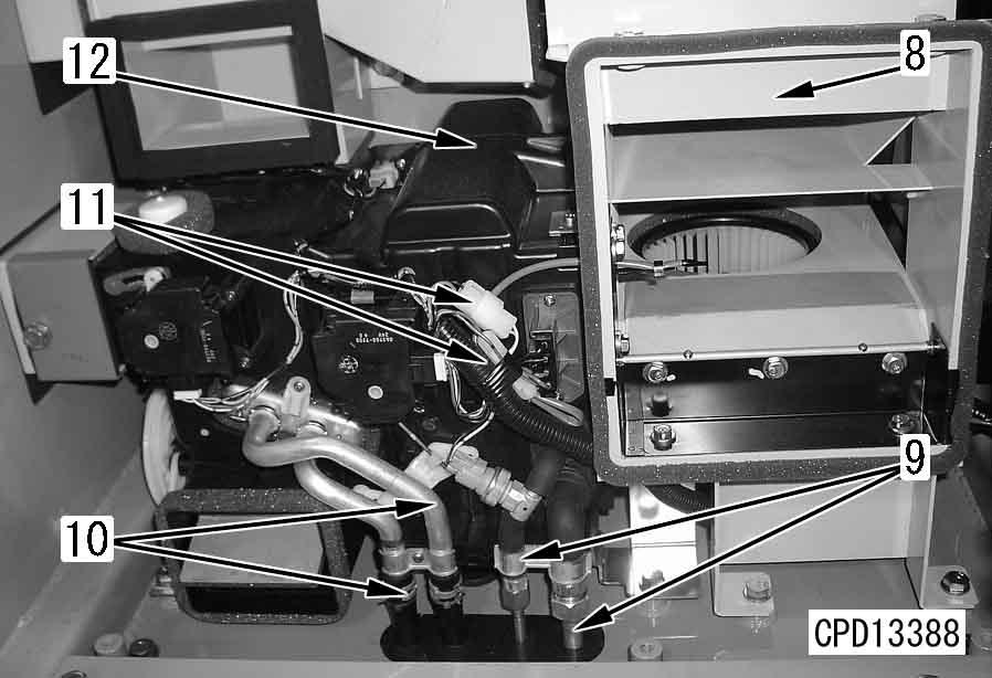
8.Disconnect 2 air conditioner hoses (9).
9.Disconnect heater hose (10).
10.Disconnect wire and wiring connector (11).
11.Remove air conditioner unit (12). a Collect the refrigerant (R134a) from the air conditioner circuit. a Plug the hoses to prevent dirt and water from entering them.
Installation q Carry out installation in the reverse order to removal.
[*1] a Install the hoses without twisting or interference. a Install the air conditioner circuit hoses carefully to prevent dirt, dust, or water from getting inside the hoses. a Check that there are O-rings at the piping connection of the ai r conditioner hoses before installing. Coat the O-rings thoroughly with compressor oil (Shell Suniso 4G or 5G). q Charging with air conditioner gas q Refilling with coolant
3 Tighten the air conditioner gas piping to the following tightening torques.
Using tool X, charge the air conditioner circuit with air conditioner gas (R134a).
Add coolant to the specified level, and run the engine to circulate the coolant through the system. Then check the coolant level again.