90 minute read
Sketchesofspecialtools1


NOTE: Komatsu cannot accept any responsibility for special tools manufactured according to these sketches. A4Plate A4Pushtool
14D475A,D475ASD-5E0
NOTE: Komatsu cannot accept any responsibility for special tools manufactured according to these sketches.
A5Pushtool E2Pushtool
D475A,D475ASD-5E015
N2Bracket
20D475A,D475ASD-5E0
Engine and cooling system (SAA12V140E-3) 1
Removal and installation of engine assembly
Special tools
1
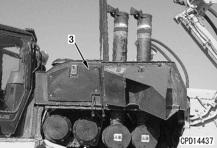
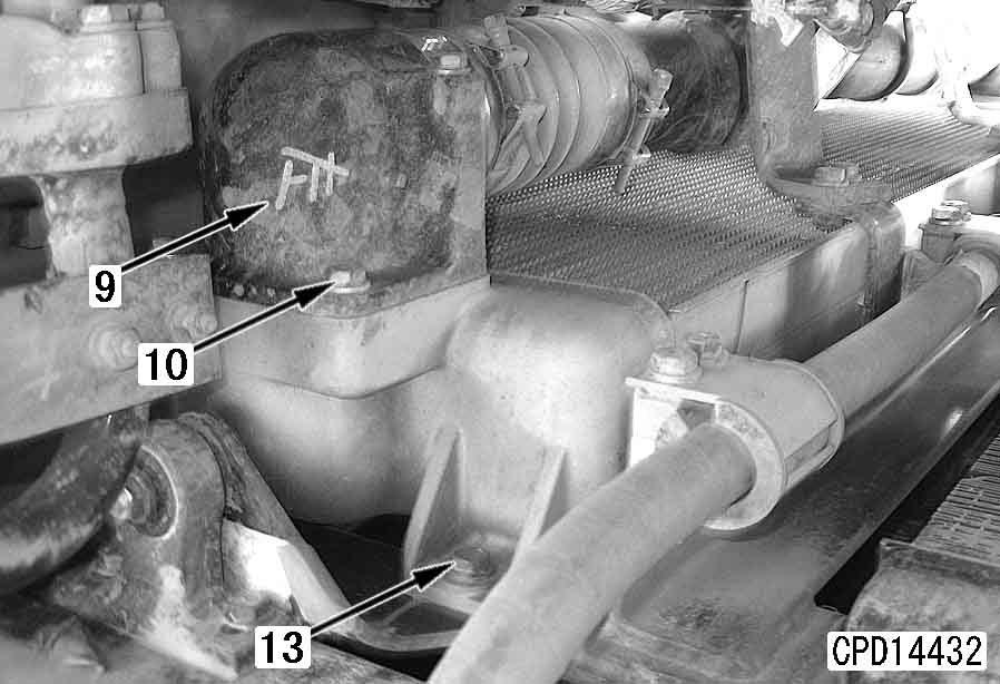
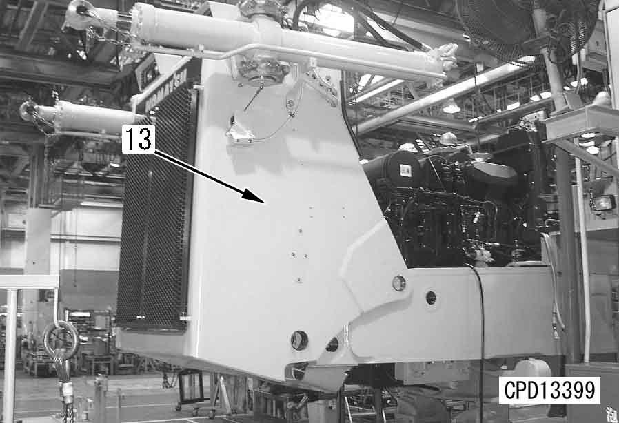
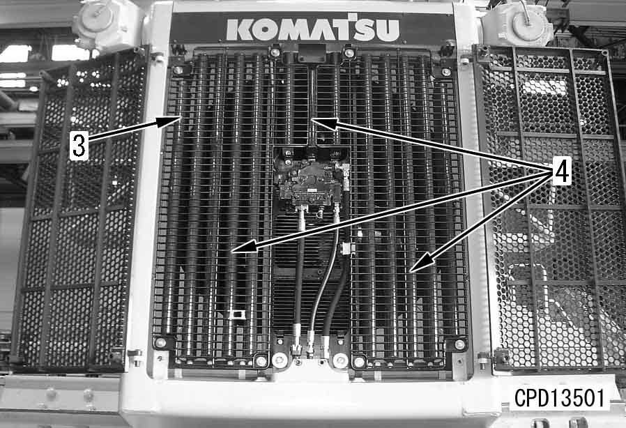
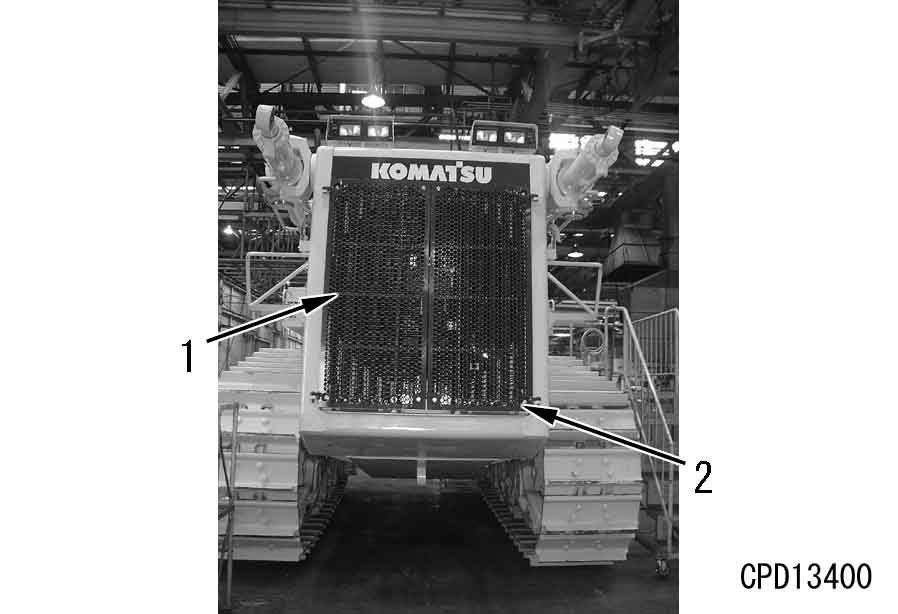
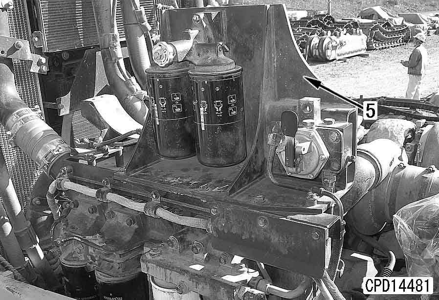
3.Lift off radiator upper cover (2).
4 Radiator upper cover assembly: 85 kg
799-703-1200Service tool kit t 1
799-703-1100Vacuum pump t 1
799-703-1111Vacuum pump t 1
799-703-1121Vacuum pump t 1
799-703-1401 Gas leak detector t 1
Removal k Lower the work equipment to the ground and stop the engine. k Set the parking brake lever and work equipment lock lever in the lock position. k Disconnect the cable from the negative (–) terminal of the battery.
1.Drain the coolant.
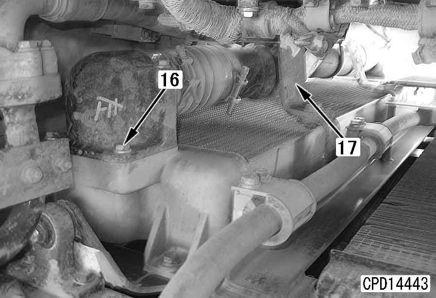
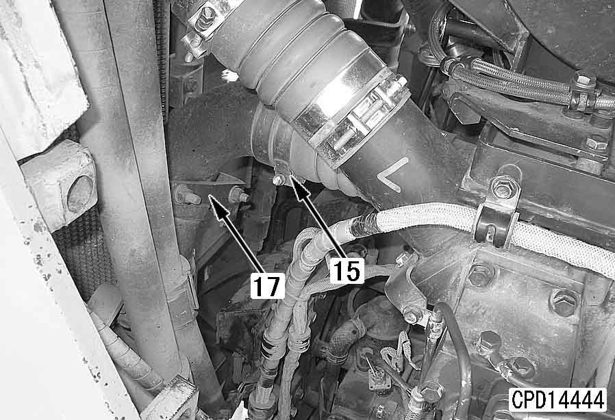
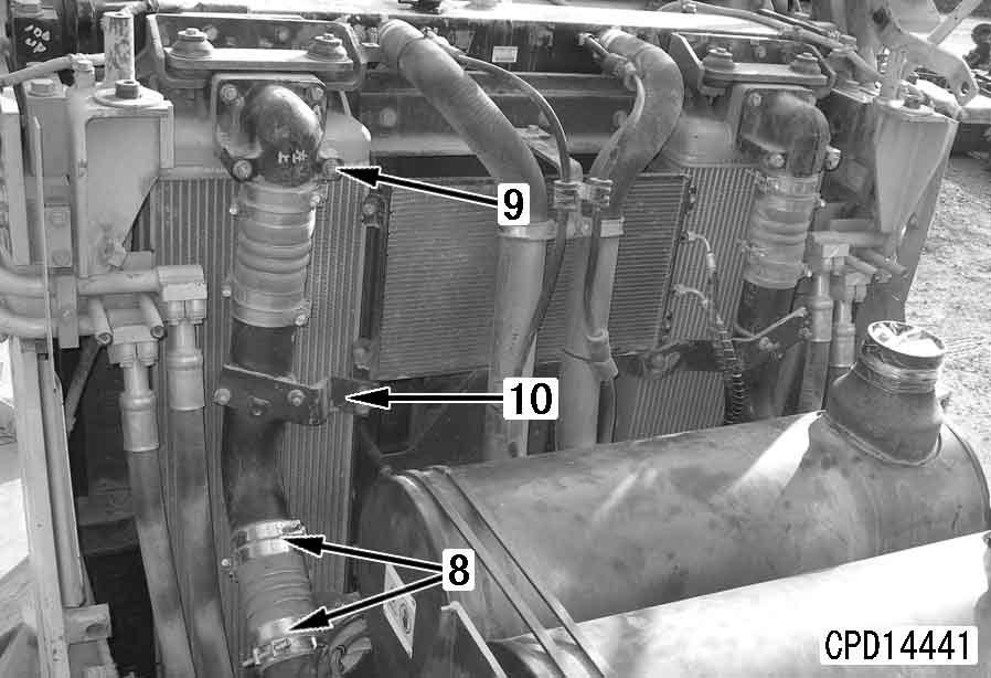
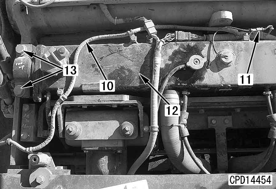
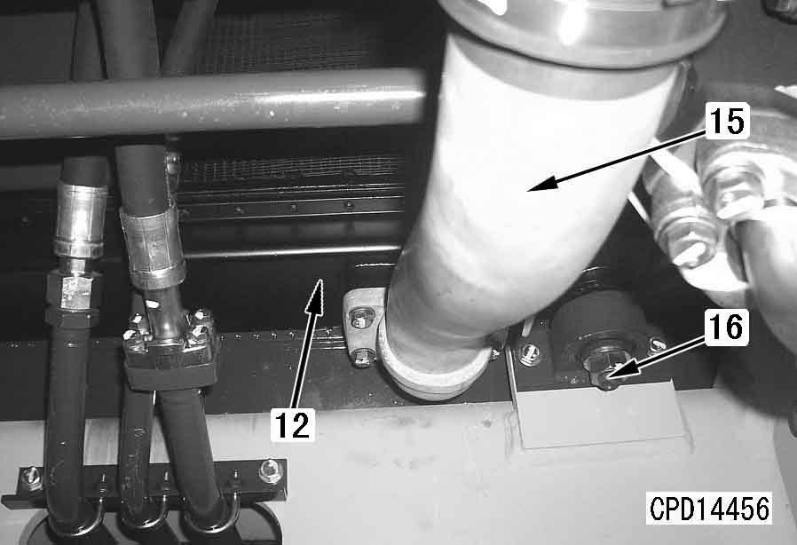
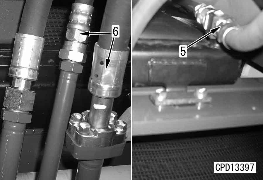
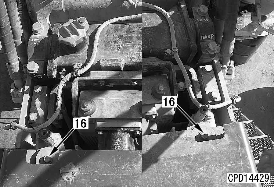
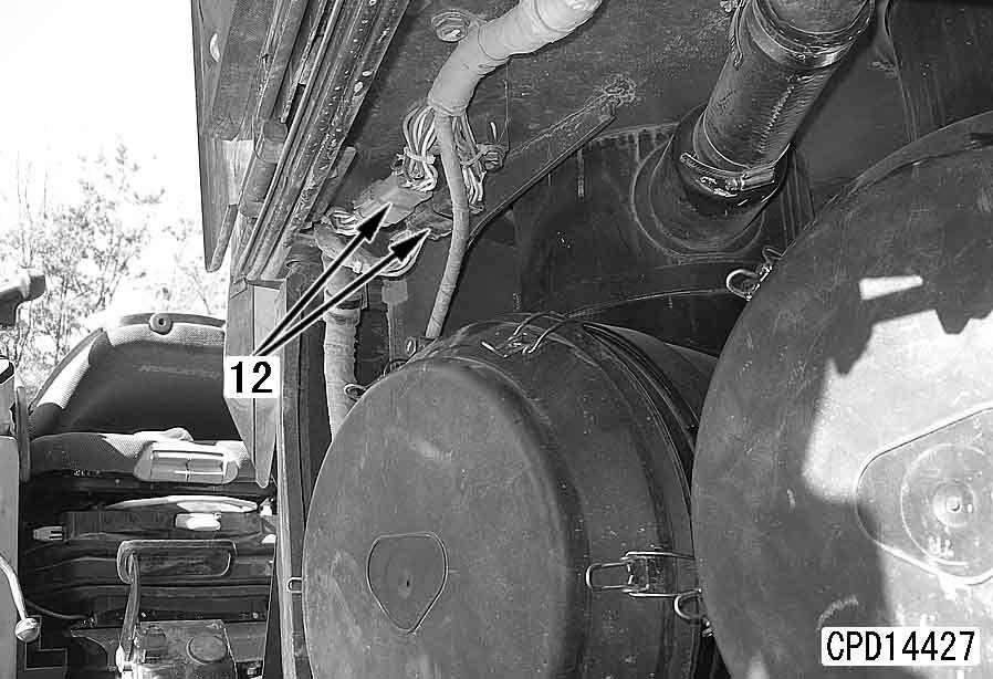
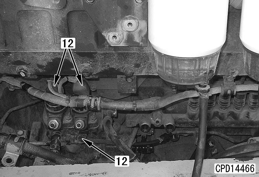
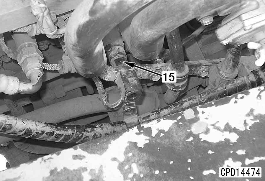
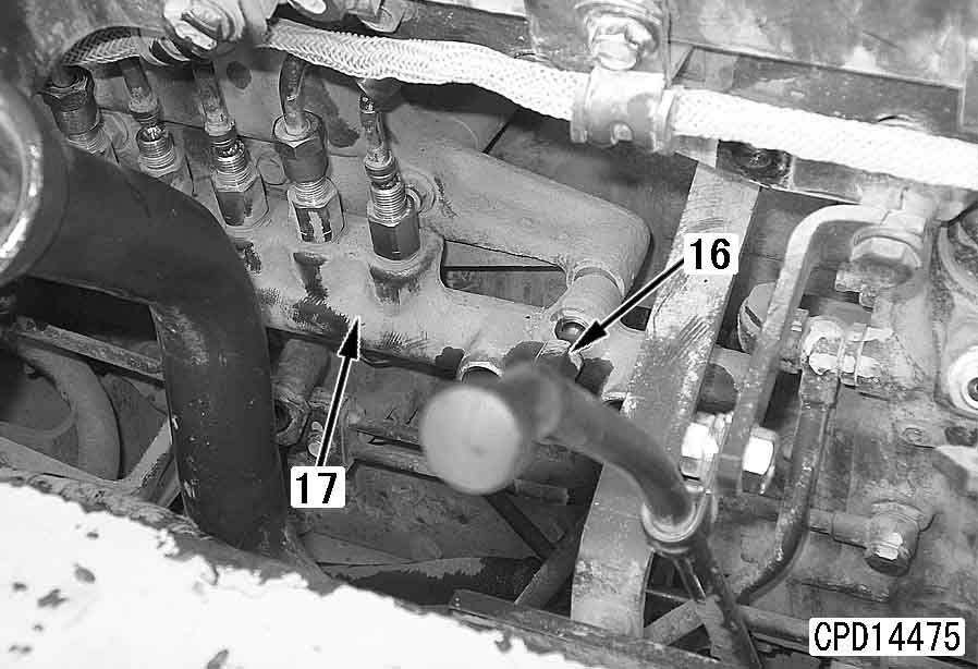
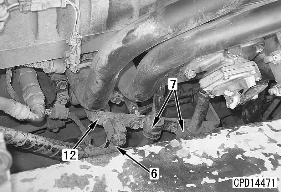
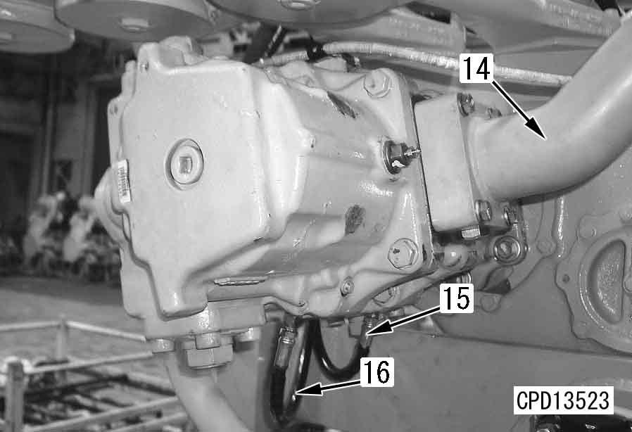
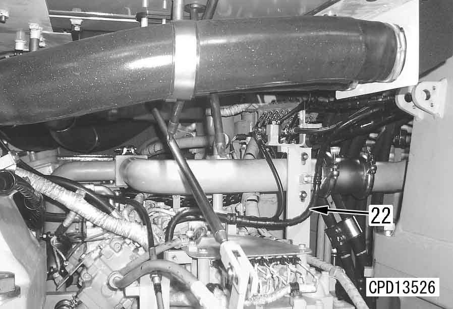
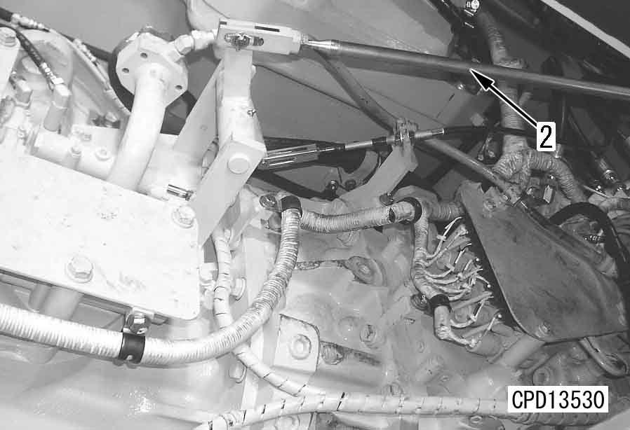
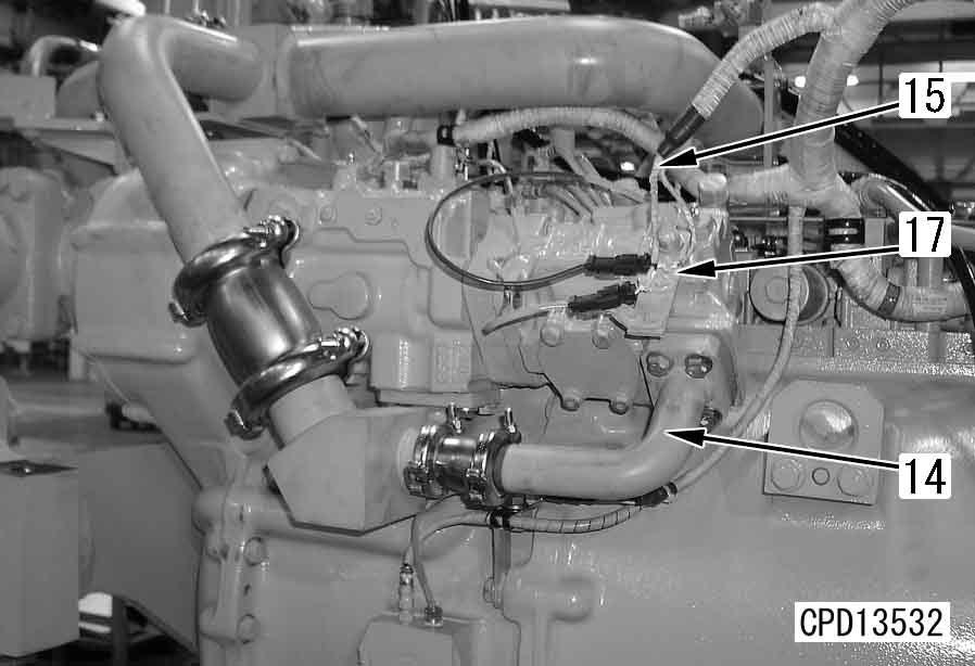
6 Coolant: 210 l a Loosen hose clamp (15). a Remove pipe mounting bolt (16). a Remove piping fixing bracket (17). a Loosen hose clamps (8). a Remove pipe mounting bolt (9). a Remove piping fixing bracket (10).
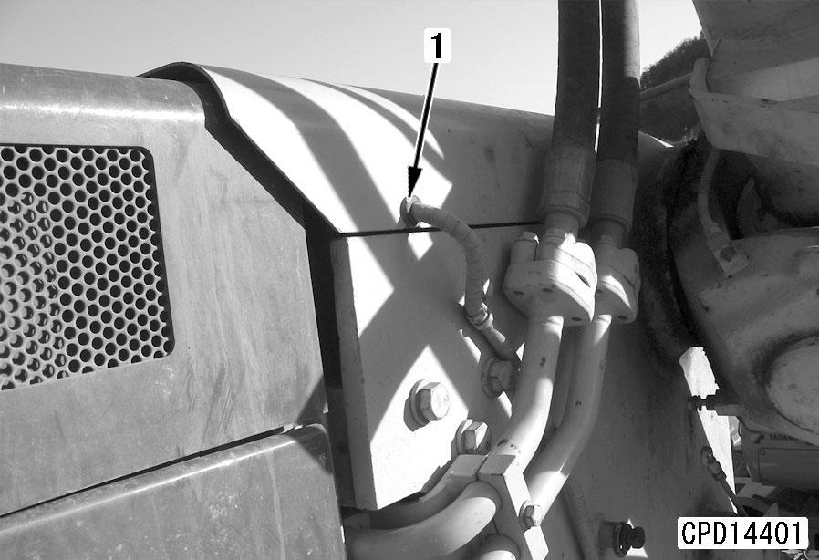
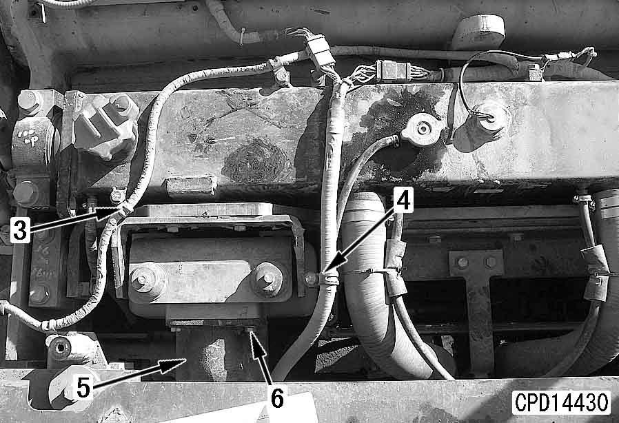
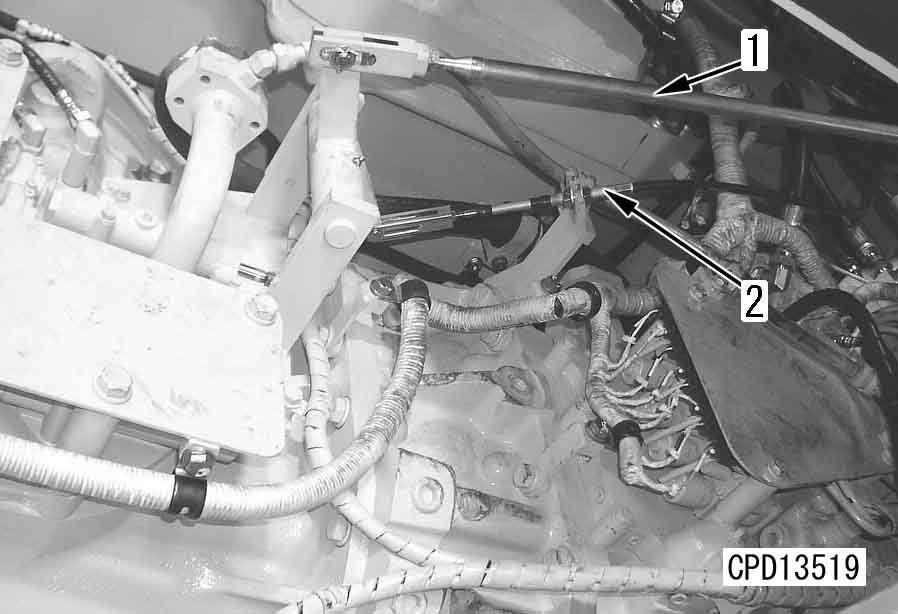
2.Remove right and left potentiometer wiring grommets (1) from the cover.
4.Remove engine hood assembly (3). For details, see "Removal and installation of engine hood assembly".
5.Remove right and left engine side covers (4) and right and left covers (5).
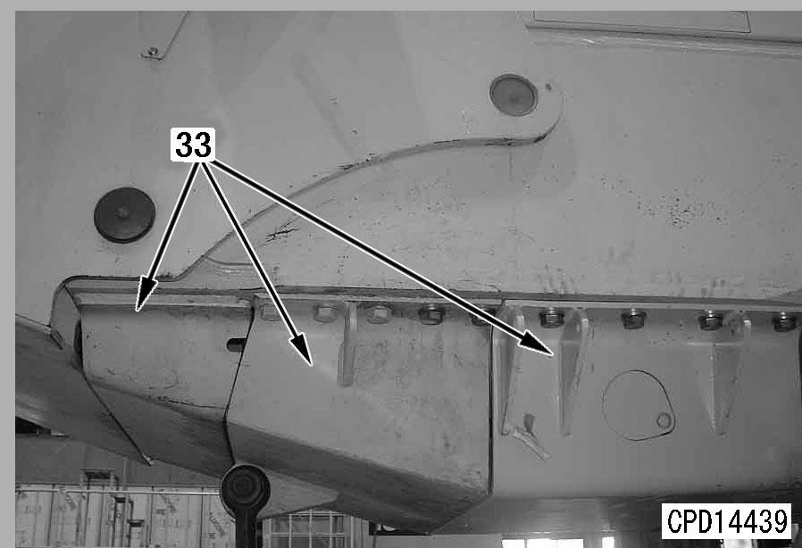
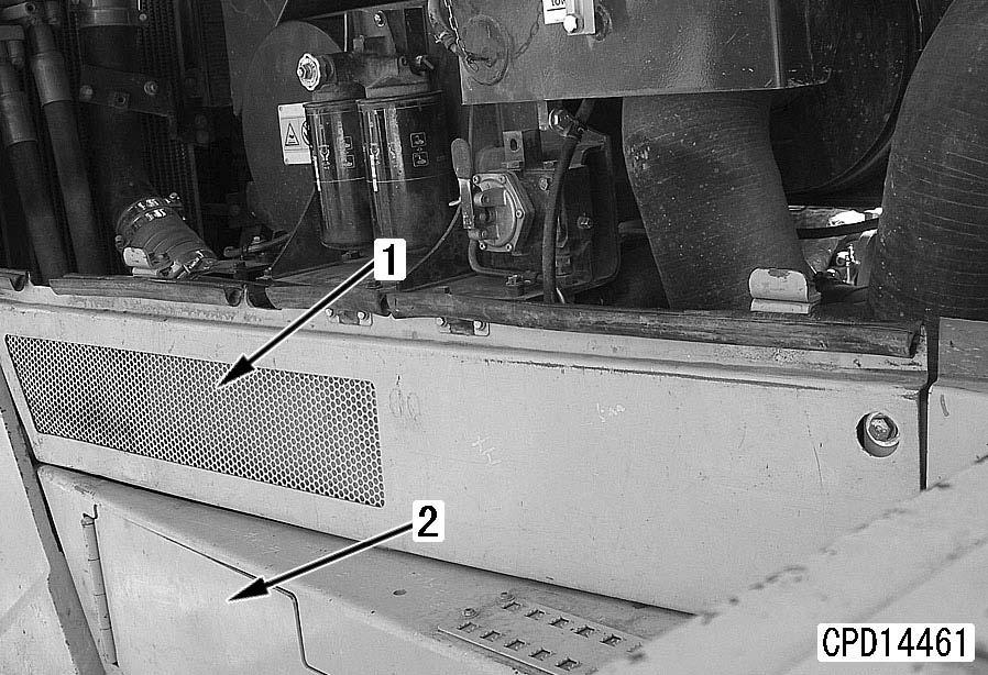
6.Remove undercovers (1st, 2nd and 3rd ones from the front) (33).
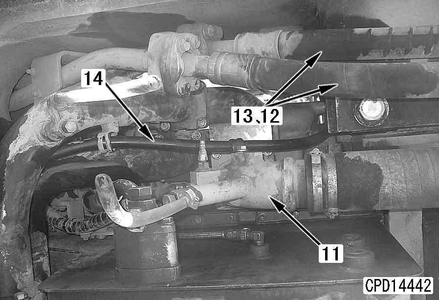
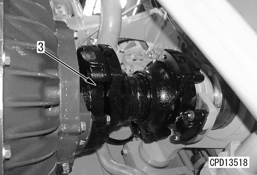
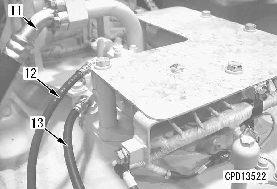
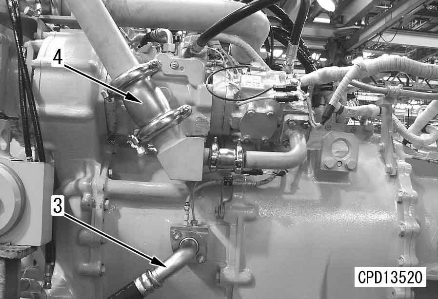
9.Disconnect radiator outlet tube (11).
10.Disconnect torque converter oil cooler tubes (12) and (13).
11.Disconnect heater hose (14).
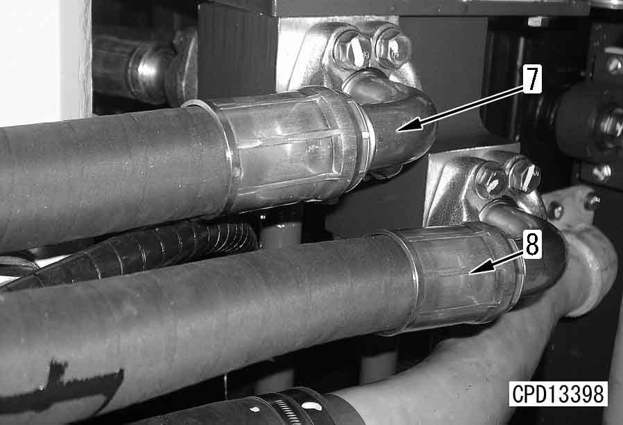
7.Disconnect radiator inlet hoses (6) and aeration hoses (7).
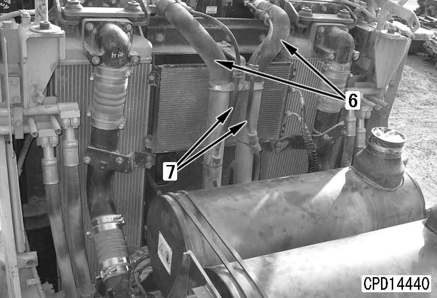
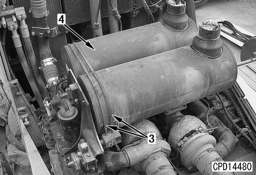
12.Lift off the right and left aftercooler outlet piping assemblies.
8.Lift off the right and left aftercooler inlet piping assemblies.
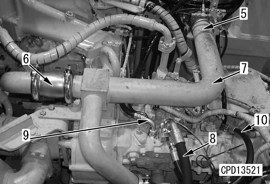
D475A, D475ASD-5E0 a Collect the air conditioner refrigerant (R134a) from the air conditioner circuit. a Cover the hoses so that dirt, water, etc. will not enter them. a Disconnect all the clamps of hose (11).
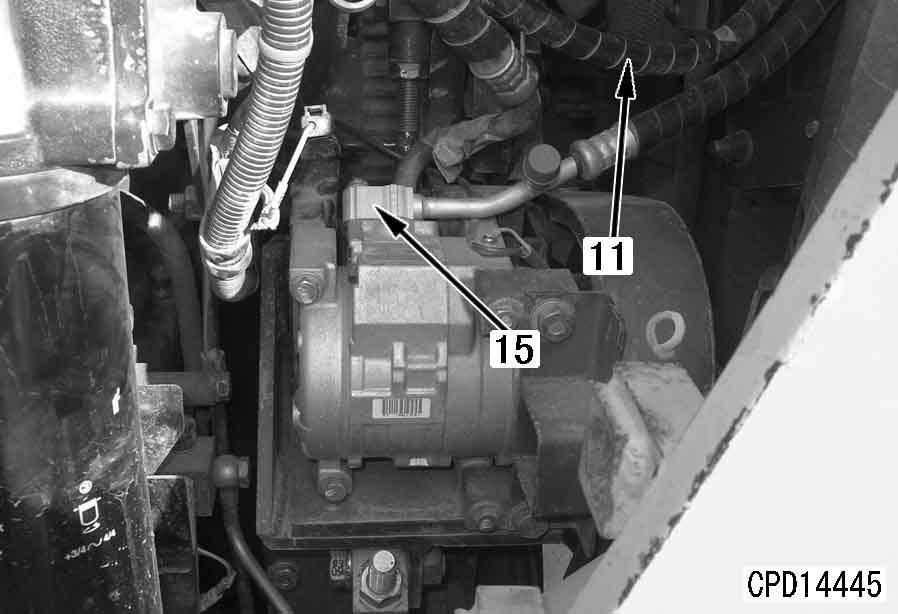
13.Disconnect air conditioner hose (15) and remove the compressor assembly.
16.Disconnect engine rear-side air conditioner hoses (23) and wiring connectors (24).
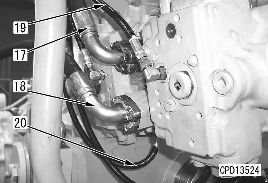
14.Remove engine lubricating oil pump hose (18), pump mounting bracket mounting bolts (19), and pump and bracket assembly (20). a Remove cables (21).
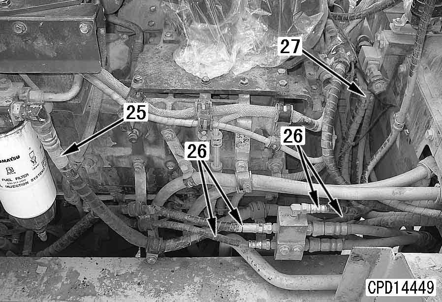
17.Disconnect fuel filter hose (25), 4 hoses (26) and heater hose (27) between the valve and engine.
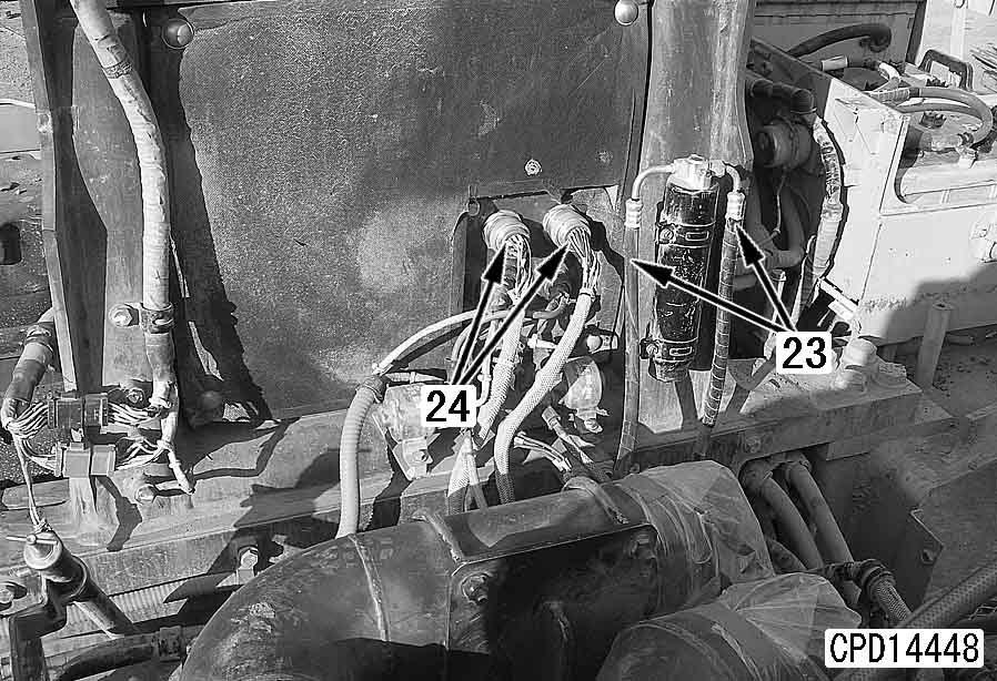
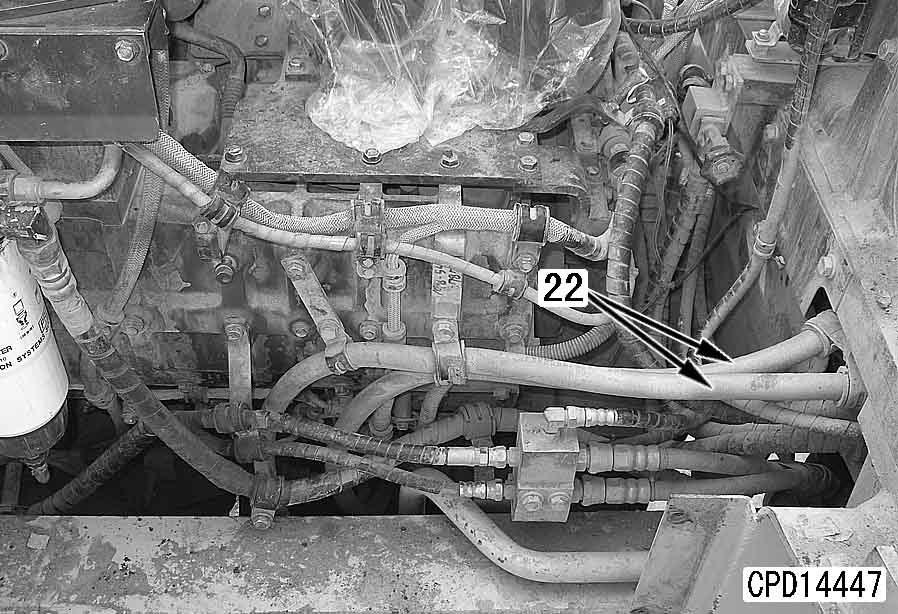
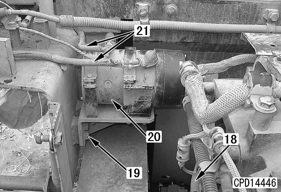
15.Remove cables (22) from the starting motor.
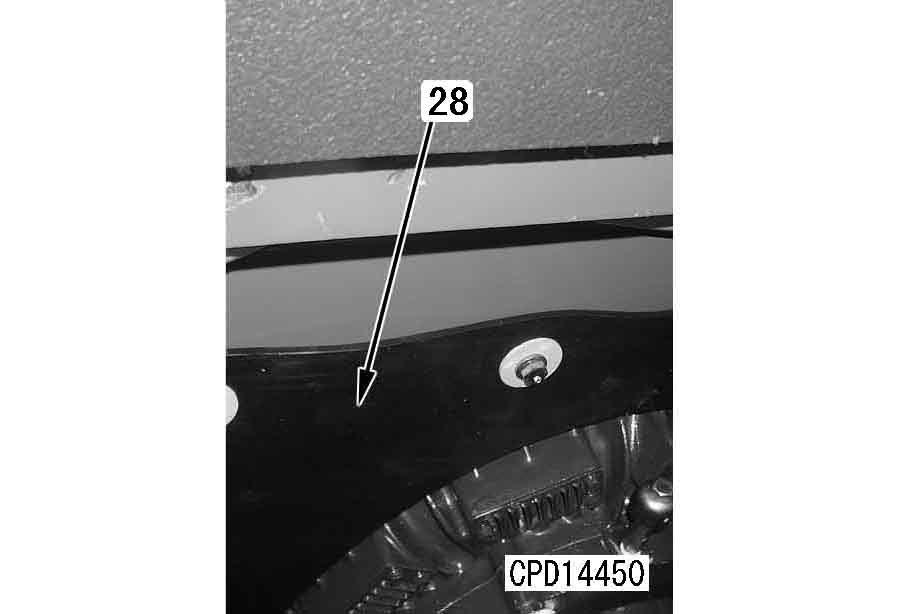
18.Remove damper rubber shield (28).
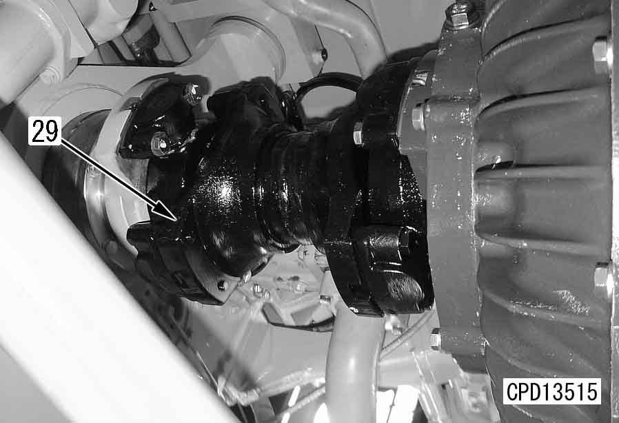
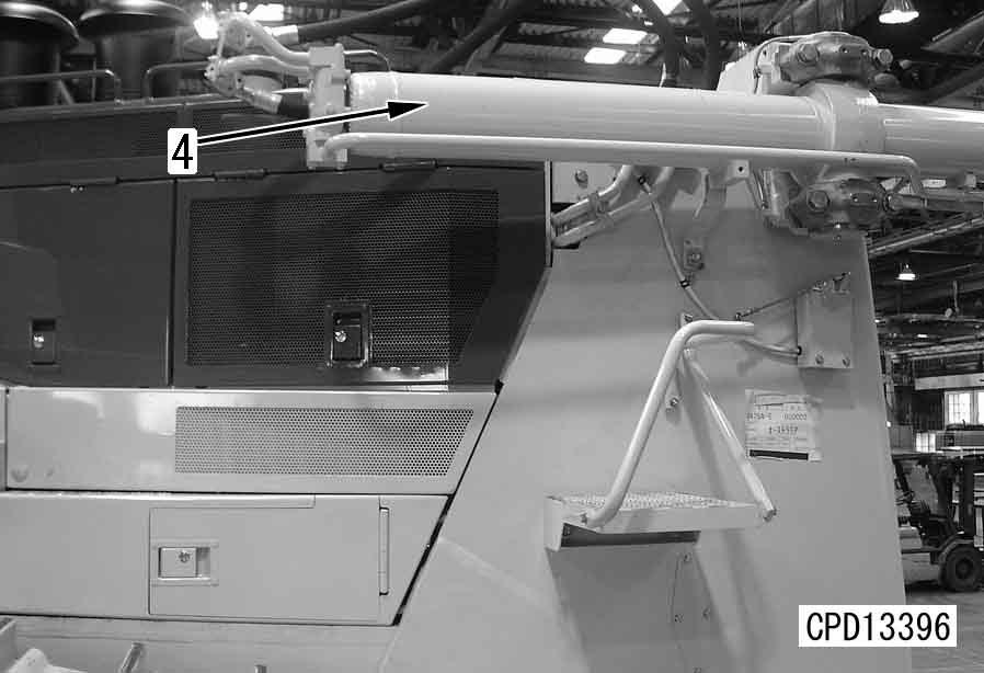
19.Sling universal joint (29), remove the mounting bolts, and lift off the universal joint.
4 Universal joint: 65 kg
Installation q Carry out installation in the reverse order to removal. q Refilling with coolant
Add coolant to the specified level, and run the engine to circulate the coolant through the system. Then check the coolant level again.
5 Coolant: 210 l
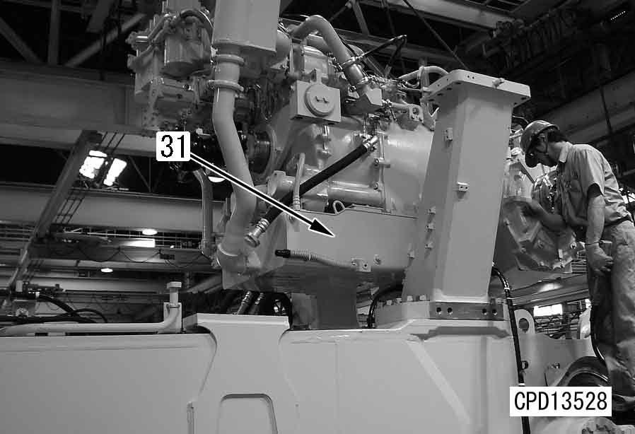
20.Remove front mounting bolt (30) and rear mounting bolt (31).
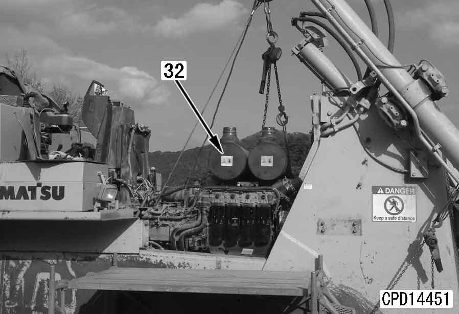
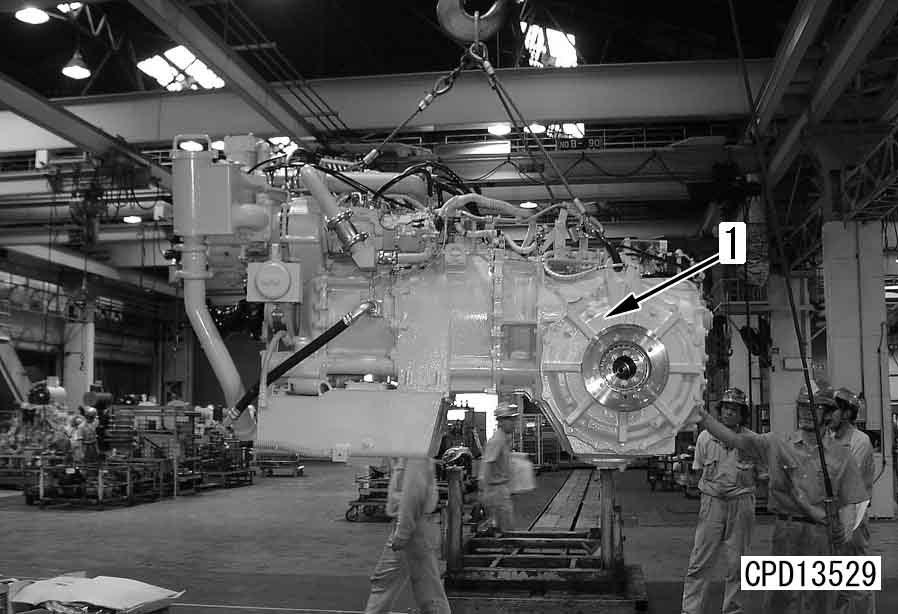
21.Remove engine assembly (32).
4 Engine assembly: 3,900 kg a When removing the engine assembly, check that all the wirings and pipings are disconnected and the engine assembly does not interfere with other parts.
D475A, D475ASD-5E0
Removal and installation of radiator assembly 1
Removal
1.Drain the coolant.
6 Coolant: 210 l
2.Remove right and left potentiometer wiring grommets (1) from the cover.
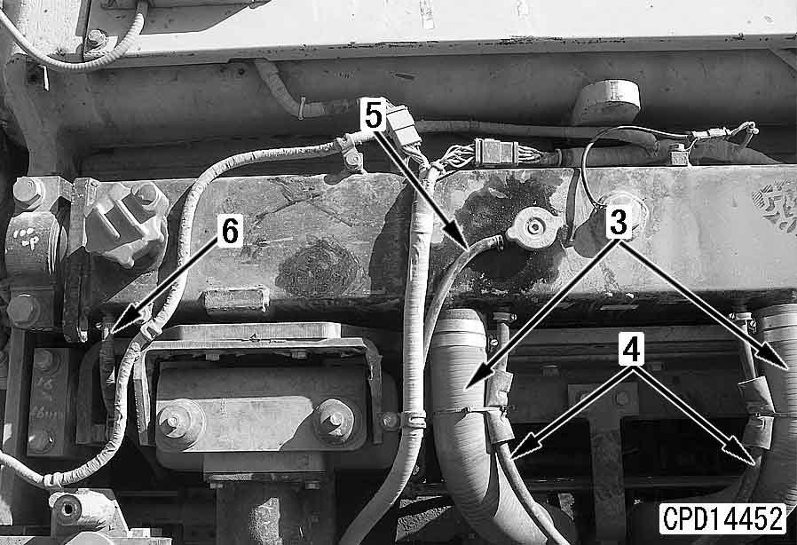
4.Disconnect radiator inlet hoses (3) (right and left) and aeration hoses (4) (right and left).
5.Disconnect sub-tank hose (5).
6.Disconnect power line cooler aeration hose (6).
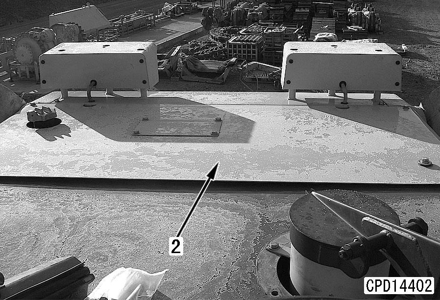
3.Lift off radiator upper cover (2).
4 Radiator upper cover assembly: 85 kg a Remove the fan motor assembly. For details, see "Removal and installation of fan motor assembly". a When removing the radiator assembly, take care not to damage its core.
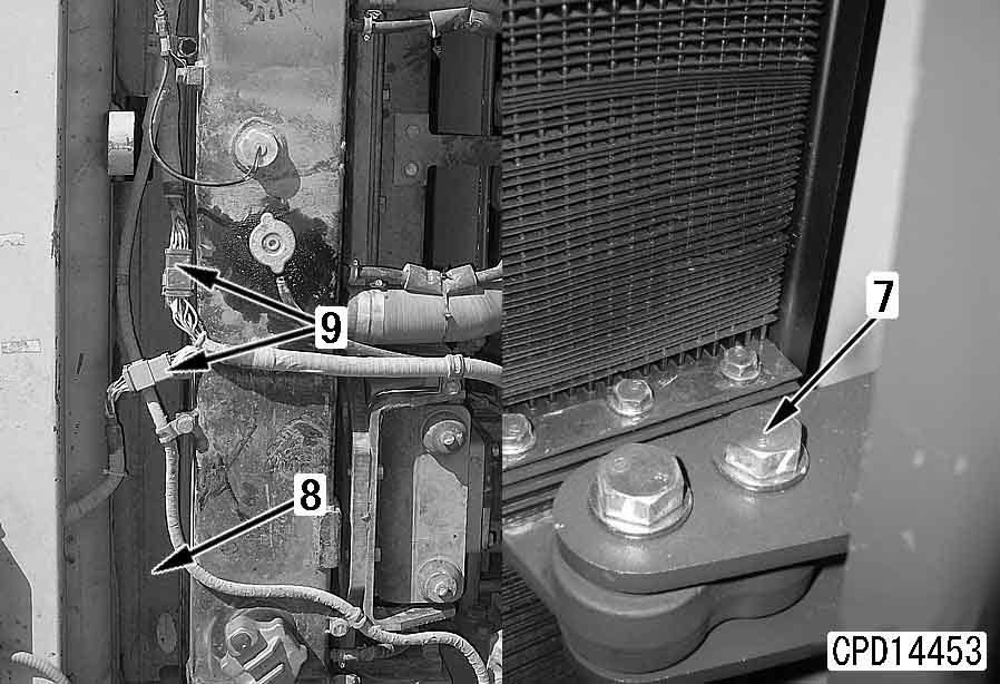
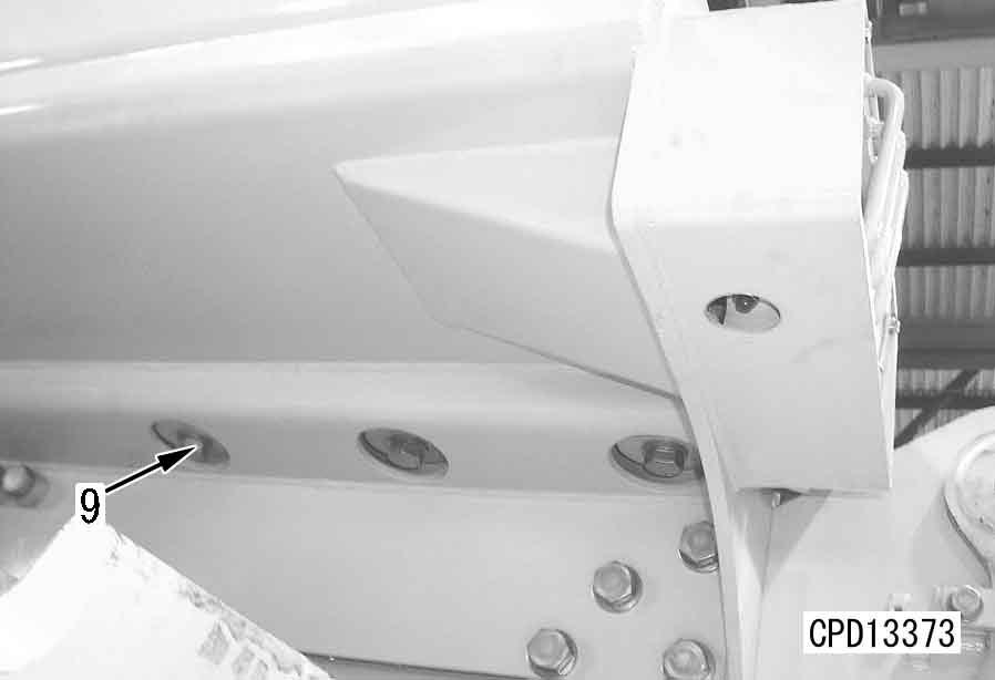
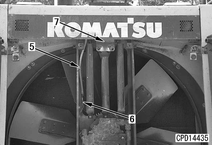
7.Remove isolator bolts (7) (2 each on the right and left sides).
8.Remove wind breaker panels (8) (upper, lower, right and left).
9.Disconnect headlamp connectors (9).
10.Disconnect radiator upper wiring harness (10) and radiator coolant level sensor connector (11).
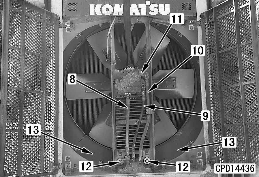
11.Sling radiator assembly (12) and remove upper mounting bolts (13) (2 each on the right and left sides).
13.Remove tube (15).
14.Lift off lower mounting bolts (16) (right and left).
15.Lift off radiator assembly (12).
4 Radiator assembly: 485 kg
12.Remove
D475A, D475ASD-5E0
Installation q Carry out installation in the reverse order to removal. q Refilling with coolant
Add coolant through the coolant filler to the specified level. Run the engine to circulate the coolant through the system. Then, check the coolant level again.
5 Coolant: 210 l
Removal and installation of aftercooler assembly 1
Removal
1.Remove right and left potentiometer wiring grommets (1) from the cover.
3.Disconnect radiator upper clamp (3) and aftercooler upper clamp (4).
4.Remove mounting bolt (6) of aftercooler upper pipe (5).
2.Lift off radiator upper cover (2). 4 Radiator upper cover assembly: 85 kg
5.Remove lower cover bolts (7) and open lower cover (8).
6.Remove mounting bolt (10) of aftercooler lower pipe (9) and aftercooler lower mounting bolt (13).
7.Sling aftercooler (11) and remove upper mounting bolts (12).
8.Move aftercooler upper pipe (5) and lower pipe (9) toward the engine and lift off aftercooler (11), taking care that the aftercooler will not interfere with the pipes.
Removal and installation of radiator guard assembly 1
Special tools
Symbol
790-431-1120Adapter t 1
791-520-4140Screw t 1
791-181-1020Sleeve t 1
791-765-1150Plate t 1
791-112-1180Nut t 1
790-101-2540Washer t 1
790-101-2102 Puller (294 kN {30 ton}) t 1
790-101-1102Pump t 1
Removal
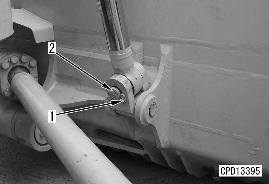
1.Remove lock plate (1) of the lift cylinder rod pin, then remove pin (2).[*1] a Start the engine and retract the piston rod fully, then tie the piston rod with wire to prevent it from coming out. a Tie the piston rod on the opposite side in the same way.
3.Sling blade lift cylinder assembly (4), then fit cylinder holder tool and secure to radiator guard.
4.Drain coolant.
6 Coolant: 210 l k Release the remaining pressure from the hydraulic circuit. For details, see Testing and adjusting, Releasing residual pressure from work equipment circuit. a Fit a cover to prevent dirt from entering the piping.
2.Remove hood assembly.
For details, see "Removal and installation of hood assembly".
Remove engine side covers (left and right).
5.Disconnect radiator inlet and outlet hoses, aeration hose, and wiring harness clip. For details, see "Removal and installation of radiator assembly".
6.Disconnect hydraulic cooler hose (5). Disconnect fan motor hose (6).
7.Disconnect
Installation q Carry out installation in the reverse order to removal.
[*1] a Standard shim thickness: 4 mm q Refilling with coolant
Add coolant to the specified level, and run the engine to circulate the coolant through the system. Then check the coolant level again.
5 Coolant: 210 l
Removal and installation of fuel tank assembly 1
Removal
1.Disconnect hose (1). a Before disconnecting the hose, close the fuel valve.
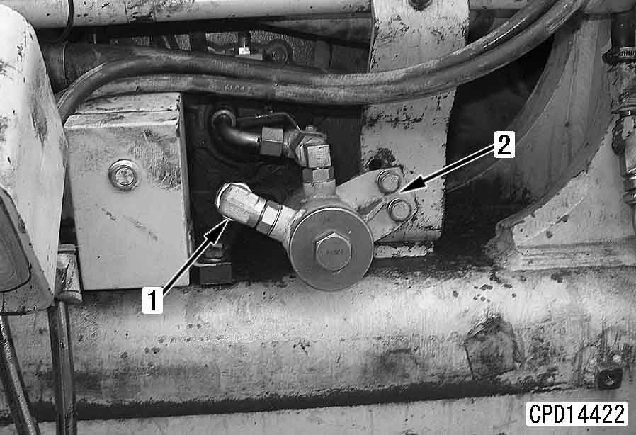
2.Remove case (2).
3.Remove joint (3) and hose clamp (4).
4.Disconnect fuel return hoses (5) and (6), and remove hose clamp (7).
5.Disconnect fuel gauge wiring connector (8).
6.Remove fuel tank mounting bolt (9).
7.Lift off fuel tank assembly (10).
4 Fuel tank assembly (when full): 2,335kg
Installation q Carry out installation in the reverse order to removal.
Removal and installation of engine hood assembly 1
Removal k Disconnect the cable from the negative (–) terminal of the battery.
1.Remove right and left potentiometer wiring grommets (1) from the cover.
3.Disconnect wiring connectors (3) (201 and 209) and remove clamp (4).
4.Disconnect hose (5) to the sub-tank and remove hose clamp (4).
2.Lift off radiator upper cover (2). 4 Radiator upper cover assembly: 85 kg
5.Open right and left covers (6) and (7).
6.Remove right and left side covers (8).
7.Loosen clamps (9) and disconnect air cleaner hoses (10).[*1]
8.Remove sub-tank drain hose clamp (11).
12.Lift off hood assembly (18). 4 Hood assembly: 600 kg
Installation q Carry out installation in the reverse order to removal.
Hose inserted length: Min. 40 mm 3 Hose clamp: 8.83 ± 0.5 Nm {0.9 ± 0.05 kgm}
Removal and installation of fan drive assembly 1
Removal
1.Drain the hydraulic oil.
6 Hydraulic tank: Approx. 340 l
2.Remove 8 mounting bolts (2) of radiator mask (1) and open the radiator mask.
5.Remove wiring harness clamp (5) and disconnect connector (6).
6.Bracket (7).
3.Remove net (3).
4.Remove fan blade (4).
7.Disconnect fan motor hoses (8), (9) and (10).
8.Sling fan drive assembly (11) and remove bracket mounting bolts (12).
9.Lift off fan drive assembly (11). 4 Fan drive assembly: 250 kg a Loosen mounting bolts (13) of the lower right and left shrouds. a Move the fan to the position shown in the photo.
Installation q Carry out installation in the reverse order to removal. q Refilling with oil (Hydraulic tank)
Add oil through the oil filler to the specified level. Run the engine to circulate the oil through the system. Then, check the oil level again.
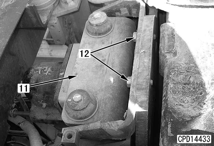
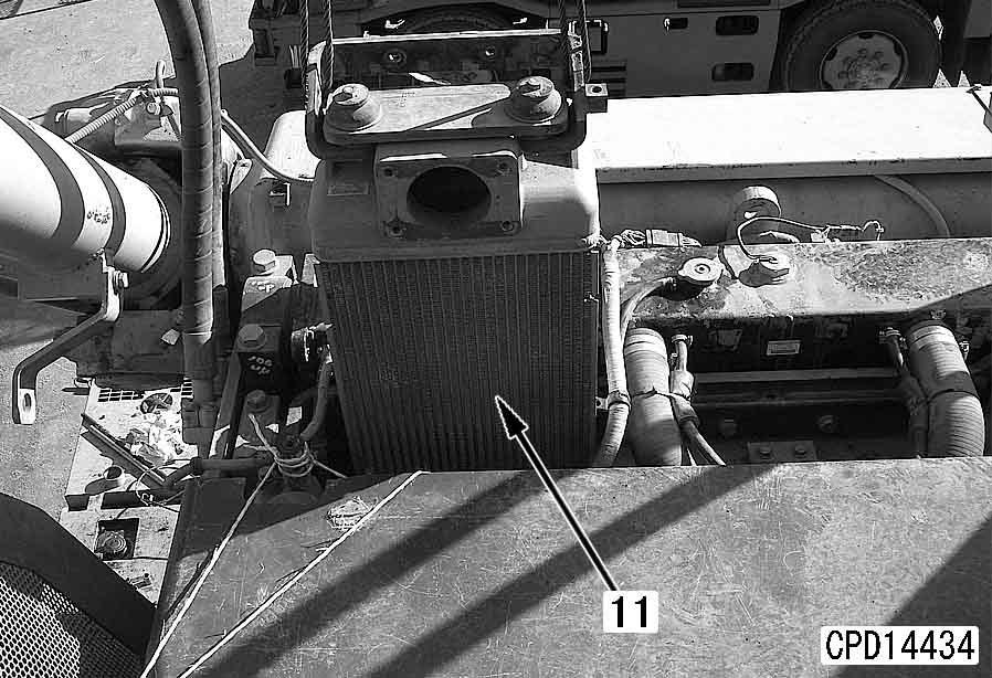
Removal and installation of fan motor assembly
Removal
1.Remove the fan drive assembly. For details, see "Removal and installation of fan drive assembly".
2.Remove the mounting bolt and lock plate (1). [*1]
3.Remove nut (2). [*2]
4.Remove fan (3).
5.Remove the 4 mounting bolts and fan motor assembly (4).[*3]
4 Fan motor assembly: 65 kg
Installation q Carry out installation in the reverse order to removal.
[*1]
Be sure to adjust the hole of lock plate (1) by turning nut (2) in the tightening direction.
[*2]
3 Mounting nut (2): 1,080 – 1,275 Nm {110 – 130 kgm} a After tightening the nut, check dimension (d) shown below. q MIN: 2.0 mm q MAX: 4.0 mm
[*3] a When fitting the fan motor and fan, clean and degrease them thoroughly.
D475A, D475ASD-5E0
D475ASD-5E0
Engine (SAA12V140E-3)
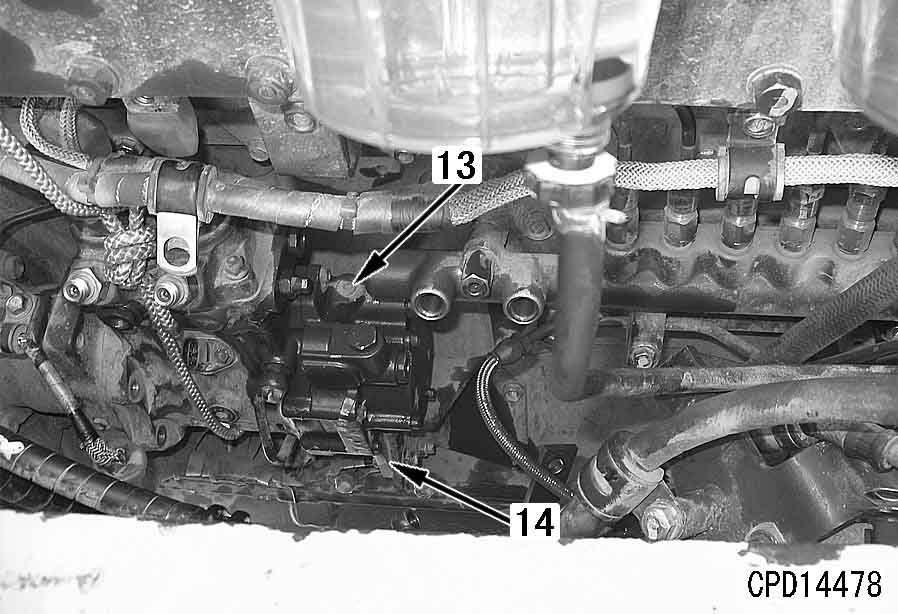
Removal and installation of fuel supply pump assembly
1
Removal of fuel supply pump on left bank side k Lower the work equipment to the ground and stop the engine. k Set the parking brake lever and work equipment lock lever in the lock position. k Disconnect the cable from the negative (–) terminal of the battery. a Do not remove the undercover.
1.Close the fuel valve under the fuel tank.
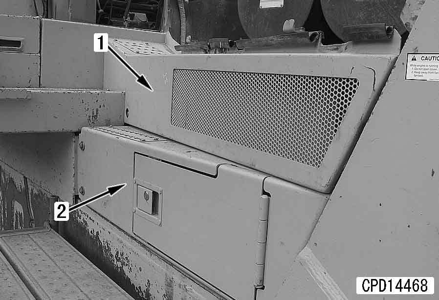
2.Remove left side cover (1) and left cover (2).
4.Remove fuel hose clamp (4) and bracket (5).
1
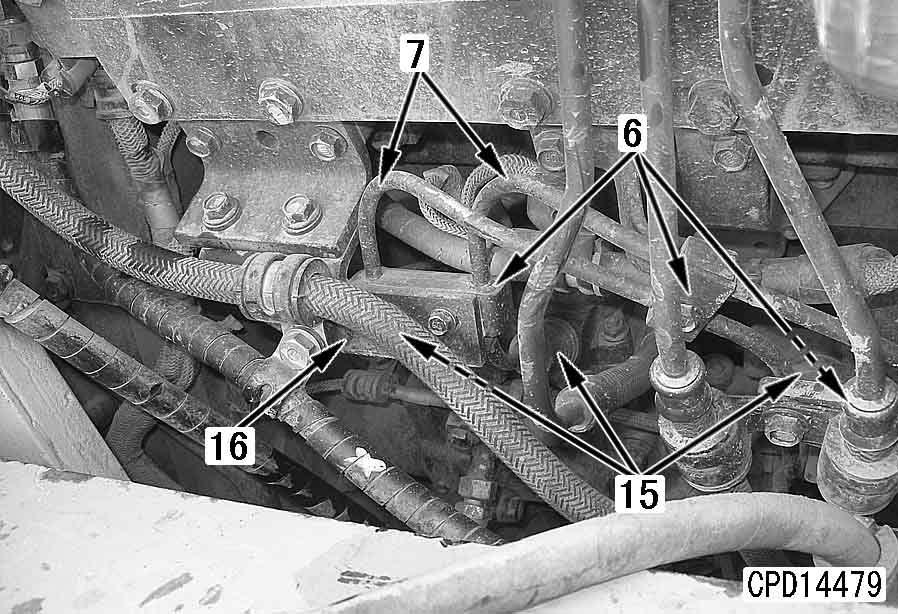
5.Remove high-pressure pipe clamp (6) and high-pressure pipe (7).
6.Remove clamp (8) and fuel tube (9). [*1]
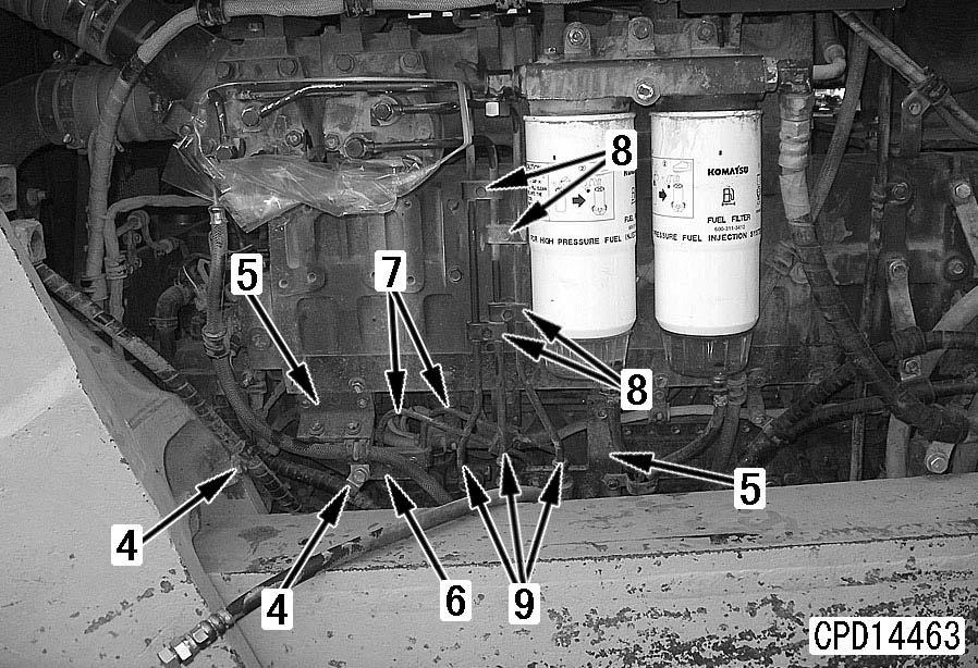
7.Remove lubrication tube (10).
9.Disconnect wiring connectors (12). a Connectors: PCV1, PCV2 and G
Removal of fuel supply pump on right bank side k Lower the work equipment to the ground and stop the engine. k Set the parking brake lever and work equipment lock lever in the lock position. k Disconnect the cable from the negative (–) terminal of the battery. a Do not remove the undercover. a Wind a rope around the fuel supply pump and sling it. a Remove the high-pressure pipe clamp just under the fuel supply pump without fail.
1.Close the fuel valve under the fuel tank.
2.Remove right side cover (1) and right cover (2).
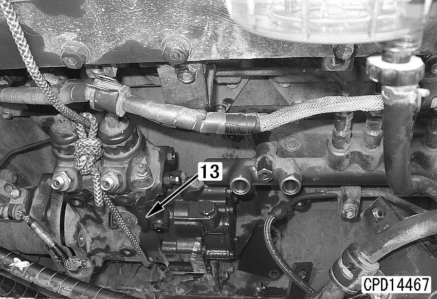
10.Remove the mounting bolts of fuel supply pump assembly (13) and pull out the fuel supply pump assembly and mounting bracket together.
4 Left fuel supply pump assembly: 17 kg a After the fuel supply pump is removed, the coupling on the drive case moves out of position. Accordingly, rotate the crankshaft to set the drive case in position when installing the fuel supply pump.
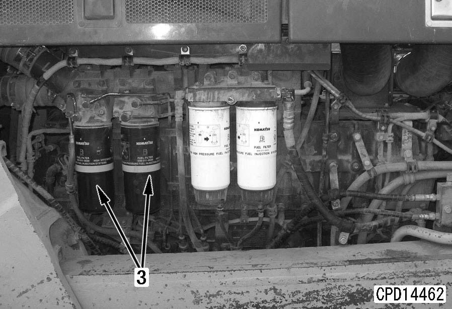
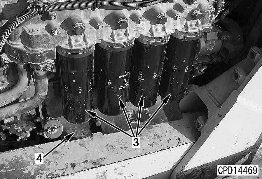
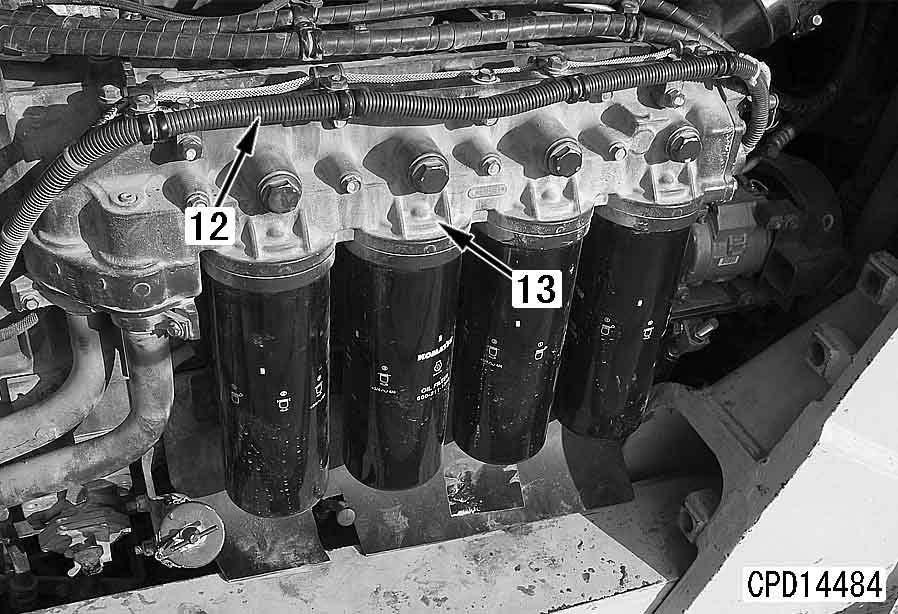
3.Remove 4 engine oil filters (3). a Use a filter wrench etc. to remove the filters.
4.Remove heat insulation plate (4).
D475A, D475ASD-5E0
5.Disconnect wiring clamp (5) and fuel hose clamps (6).
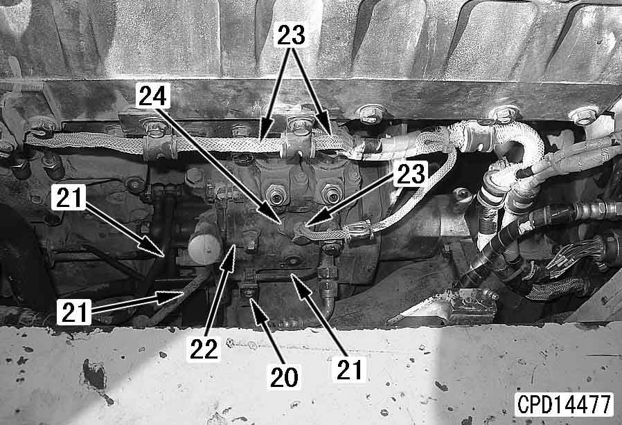
7)Disconnect 6 upper high-pressure pipes (13) of the common rail and high-pressure pipes (14) on this side.
7.Remove the common rail according to the following procedure.
1)Remove clamp (8).
2)Remove the common rail cover mounting bolts to drop cover (9).
3)Remove clamp (10).
4)Remove high-pressure pipe (11).
5)Remove bracket (12).
6)Remove common rail cover (9).
8)Disconnect common rail wiring connector (15).
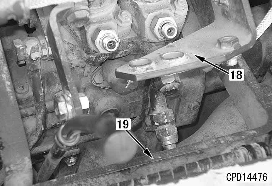
9)Remove right and left mounting bolts (16) to remove common rail (17).
8.Remove brackets (18) and (19).
Installation a
The following is the installation procedure for the left bank fuel supply pump assembly. The basic installation procedure for the right fuel supply pump assembly is the same.
1.Install supply pump assembly (13) temporarily.
2 Supply pump assembly mounting bolt: Adhesive (LT-2) a Before tightening the mounting bolt on the pump side and mounting bolt (14) on the engine mounting bracket side to the specified torque, tighten the sleeve nuts of the high-pressure pipe (between the supply pump and common rail).
9.Remove clamp (20) and fuel tube (21).
10.Remove lubrication tube (22).
11.Disconnect wiring connectors (23). a Connectors: PCV1, PCV2 and G a Wind a rope around the fuel supply pump and sling it. a Remove the high-pressure pipe clamp just under the fuel supply pump without fail.
12.Remove the mounting bolts of fuel supply pump assembly (24) and pull out the fuel supply pump assembly and mounting bracket together.
4 Right fuel supply pump assembly: 17 kg a After the fuel supply pump is removed, the coupling on the drive case moves out of position. Accordingly, rotate the crankshaft to set the drive case in position when installing the fuel supply pump.
2.Connect the wiring connector (12).
3.Remove common rail cover (11).
D475A, D475ASD-5E0
High-pressure pipe
k When handling the high-pressure pipe and clamp, observe the following.
q Never bend the high-pressure pipe to correct before installing or use it for another section.
q Install the specified clamp to the specified position securely and tighten it to the specified torque.
q Do not apply lubricant to the high-pressure pipe sleeve nut and the threads of the mating part.
a If lubricant is applied, the axial tension is increased too much and the highpressure pipe may be broken when the sleeve nut is tightened.
k Before installing the high-pressure pipe, check it. If it has any defect, replace it since fuel may leak.
q Check the taper seal of the connecting part (Part "a": Part of 2 mm from the end) for visible lengthwise slit "b" and dent "c".
q Check part "d" (End of the taper seal: Part at 2 mm from the end) for stepped-type wear (fatigue) which your nail can feel.
3 Bracket mounting bolt (14): 19.6 – 29.4 Nm {2.0 – 3.0 kgm}
4)Install lubrication tube (10).
3 Lubrication tube joint bolt: 9.8 – 12.7 Nm {1.0 – 1.3 kgm} a When tightening the high-pressure pipe clamp mounting bolts, take care extremely that an excessive force will not be applied to the mounting area on the supply pump side.
5)Install high-pressure pipe clamp (6) according to the following procedure.
1]Finger tighten all the mounting bolts of high-pressure pipe clamp (6) and bracket (16).
2]Tighten the high-pressure pipe clamp (6) mounting bolts permanently.
3 Clamp bolt: 9.8 ± 1 Nm {1 ± 0.1 kgm} a Install the rubber covers so that their slits will be directed as follows. q Supply pump side: Down q Common rail side: Inward (Facing each other) a Using a spanner-type torque wrench (commercially available), control the tightening torque.
3]Tighten bracket (16) mounting bolts permanently.
6)Install 4 rubber covers (15) to the highpressure pipe sleeve nuts.
4.Install the high-pressure pipe according to the following procedure.
1)Install high-pressure pipe assembly (7) and then tighten the sleeve nuts to the specified torque.
3 High-pressure pipe sleeve nut
(Supply pump side):
39.2 – 49 Nm {4 – 5 kgm}
High-pressure pipe sleeve nut (Common rail side):
39.2 – 58.8 Nm {4 – 6 kgm} q Carry out the following installation in the reverse order to removal.
2)Tighten the supply pump assembly mounting bolts.
3)Tighten supply pump assembly bracket (14) mounting bolts.
[*1]
3 Joint bolt on main fuel filter (upper) side: 24.5 – 34.3 Nm {2.5 – 3.5 kgm}
3 Joint bolt on fuel supply pump side: 14.8 – 19.6 Nm {1.5 – 2.0 kgm} k Check that each high-pressure pipe is at least 10 mm apart from the wiring harness around it.
D475A, D475ASD-5E0
Removal and installation of cylinder head assembly
Special tools
1
Removal k Lower the work equipment to the ground and stop the engine. k Set the parking brake lever and work equipment lock lever in the lock position. k Disconnect the cable from the negative (–) terminal of the battery.
1.Close the fuel valve under the fuel tank.
2.Remove the engine hood. For details, see "Removal and installation of engine hood".
3.Remove right and left engine side covers (1) and right and left covers (2).
4.Remove mounting bands (3) and connector nuts and then wind a rope around muffler assembly (4) and lift it off.
4 Muffler assembly: 60 kg (1 piece)
5.Remove the piping and then remove the corrosion resistor, air bleeding valve and mounting bracket (5) together.
4 Corrosion resistor, air bleeding valve and mounting bracket: Approx. 35 kg
6.Remove muffler mounting bracket (6).
4 Muffler mounting bracket: 38 kg
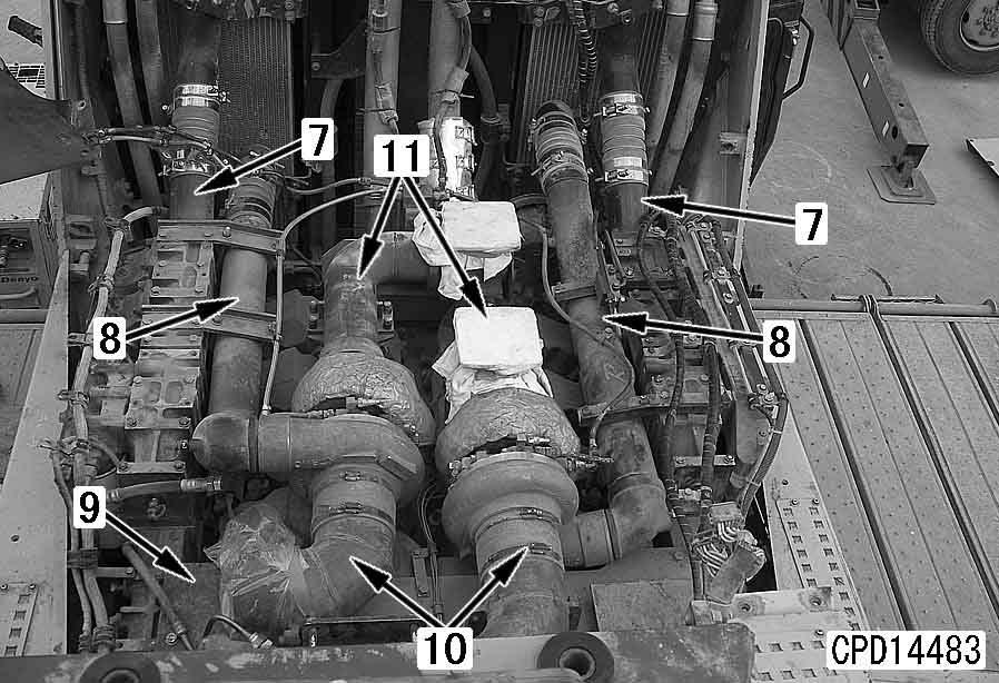
7.Remove aftercooler inlet pipe (7) and aftercooler outlet pipe (8). [*1]
8.Remove bracket (9) and turbocharger intake connector (10) together. [*2]
9.Remove turbocharger exhaust connector (11).
14.Remove the common rail cover. For details, see "Removal and installation of fuel supply pump assembly".
15.Remove right and left rubber covers (17) and (18).
16.Remove right and left high-pressure pipes (19).
10.Disconnect right and left main wirings (12).
11.Remove engine oil filter assembly (13).
17.Remove right and left air intake manifolds (20). 4 Air intake manifold: 35 kg
12.Disconnect fuel hose and piping (14). [*3]
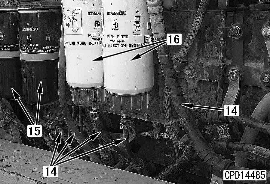
13.Remove main fuel filter assembly (15) and fuel prefilter assembly (16).
D475A, D475ASD-5E0 q Lubrication tube (21) q Lubricating oil drain tube (22) q Coolant tube (23)[*4] q Coolant drain tube (24)[*4]
18.Remove each tube of the turbocharger.
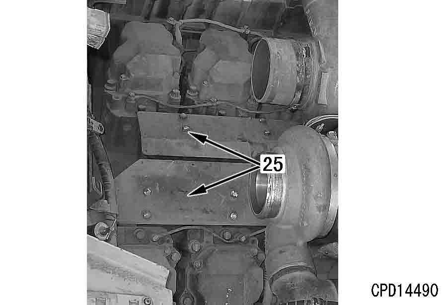
19.Remove heat insulation cover (25).
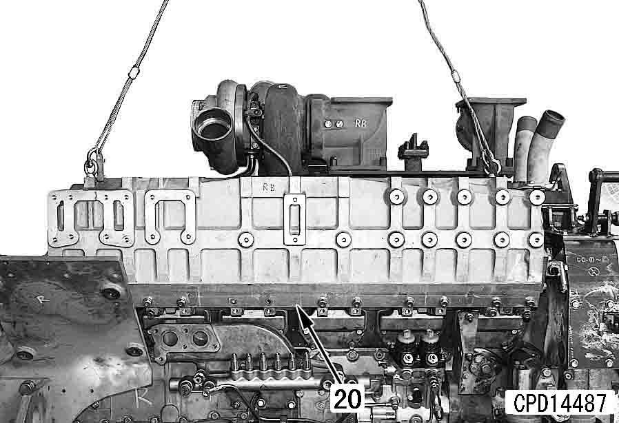
20.Sling turbocharger and exhaust manifold assembly (26), remove the mounting bolts, and lift off the turbocharger and exhaust manifold assembly.[*5]
4 Turbocharger and exhaust manifold assembly: 60 kg
21.Removal of injector external wiring
1)Remove cover plate (27).
2)Disconnect connector (28) from each cylinder head and disconnect wiring harness (29).
22.Remove air vent tubes (30) and (31). [*6]
23.Remove spill tube (32).
24.Remove head cover (33).
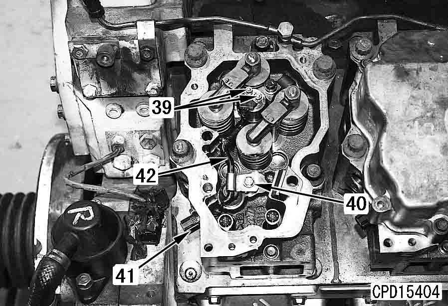
25.Removal of rocker arm assembly
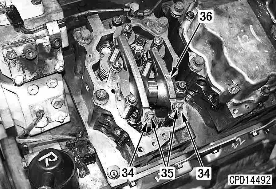
1)Loosen locknuts (34) and then loosen adjustment screws (35) fully. a Check that the rocker arm is not affected by the valve tension but it is free.
2)Remove rocker arm assembly (36). a Put a location tag to each rocker arm assembly before storing.
26.Remove push rods (37).
27.Remove crossheads (38).
28.Removal of fuel injector
1)Remove injector terminal mounting nuts (39).
2)Remove clamp mounting bolt (40).
3)Push connector (41) into the cylinder head and remove injector wiring harness (42).
4)Remove holder mounting bolt (43).
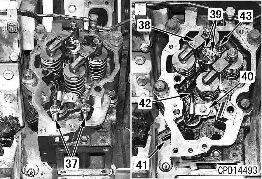
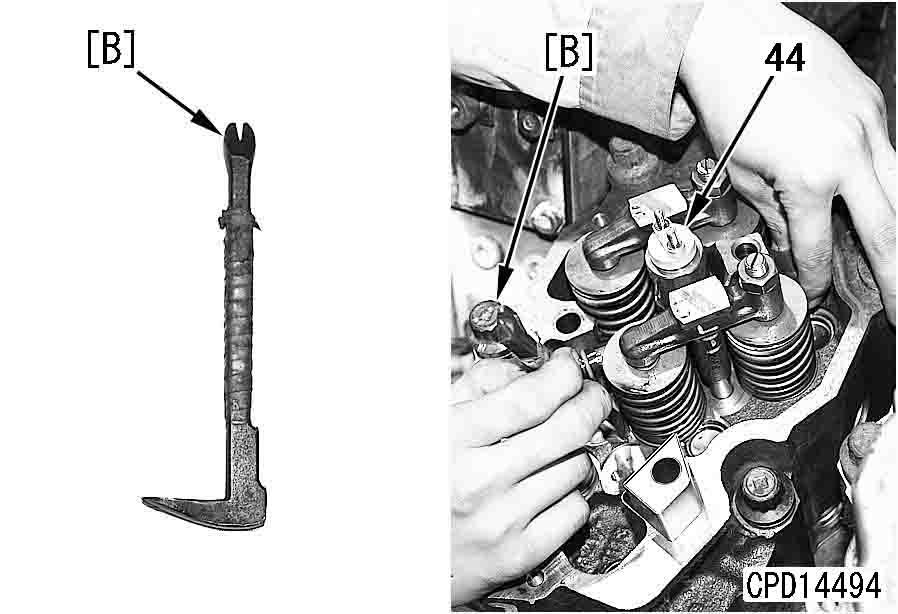
5)Insert small L-bar [B] under the fuel connector and pry out fuel injector (44) slowly. a Do not grip the solenoid valve at the top of the injector with pliers to pull out the injector.
Installation
Cylinder head assembly
1.Install the cylinder head gasket.
2.Sling and install cylinder head assembly (45).
4 Cylinder head assembly: 30 kg
29.Lift off cylinder head assembly (45).
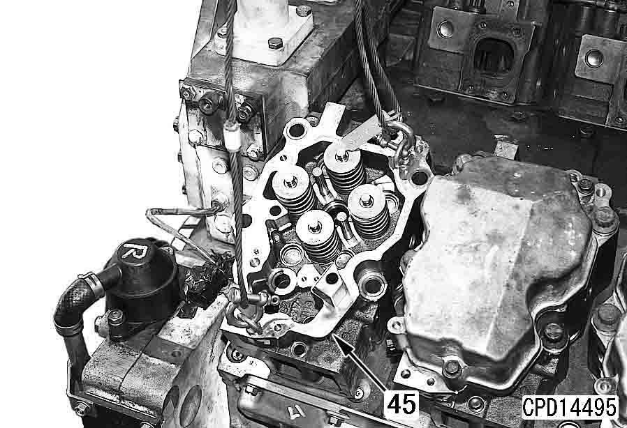
4 Cylinder head assembly: 30 kg a If the cylinder head assembly is removed without removing the fuel injector, the injector tip projects from the bottom of the cylinder head. Accordingly, use a block, etc. to prevent the injector from interfering with the floor. a If there are 5 punch marks on the head of a bolt, do not reuse that bolt but replace it. a Tighten the mounting bolts in the order shown in the figure.
2 Cylinder head assembly mounting bolt: Molybdenum disulfide grease (LM-P)
3 Cylinder head assembly mounting bolts (1) – (6):
1st time: 137 – 157 Nm {14 – 16 kgm}
2nd time: 284 – 294 Nm {29 – 30 kgm}
3rd time: Retighten by 90 – 120°
3 Cylinder head assembly mounting bolt (7): 66.2 ± 7.4 Nm {6.75 ± 0.75 kgm} a Use tool A2 (See the tool table) to retighten the mounting bolts. When not using tool A2 , make marks on the bolts and cylinder head, and then retighten each bolt by 90 – 120° a After tightening the bolts, make punch mark "a" on the main bolt head (Do not make it when new bolts are used, however).
6.Install spherical washer (50) to injector holder mounting bolt (43) and tighten injector holder (49) temporarily.
2 Spherical washer: Engine oil (EO30) a Tighten injector holder (49) permanently after tightening the high-pressure pipe temporarily.
Fuel injector a Check that there is no dirt in the injector sleeve.
2 O-ring: Engine oil (EO30)
3.Fit O-rings (46) and (47) to fuel injector (44). a Take care not to fit O-ring (47) to center groove (A)
4.Install gasket (48) to fuel injector (44).
5.Insert fuel injector (44) and injector holder (49) together in the cylinder head.
Crosshead
7.Install crossheads (38).
2 Sliding parts of crosshead: Engine oil (EO30)
8.Adjust the crosshead according to the following procedure.
1)Loosen locknut (102) and then loosen adjustment screw (103) to a position where it will not touch valve stem (104).
2)Hold the contact face to the rocker arm with the finger to keep crosshead in contact with valve stem (105) on the push rod side.
3)Tighten adjustment screw (103) slowly and check the point at which adjustment screw (103) touches valve stem (104).
4)Tighten adjustment screw (103) further by 20 – 30° from the above point.
5)While holding adjustment screw (103), tighten locknut (102).
3 Locknut: 58.8 ± 5.9 Nm {6.0 ± 0.6 kgm} a Check that each push rod end is fitted in the receiving area of the cam follower.
10.Install push rods (37).
2 Both ends of push rod: Engine oil (EO30)
9.Injector wiring harness a Tighten injector terminal mounting nuts (39) alternately.
1)Push out connector (41) from inside of the cylinder head and inst all injector wiring harness (42) in the cylinder head.
2)Tighten injector terminal mounting nuts (39) and clamp mounting bolt (40).
3 Injector terminal mounting nut: 2 ± 0.2 Nm {0.2 ± 0.02 kgm} a After tightening the injector terminal mounting nuts, press the wiring harness against the injector body to take up the slack.
11.Install rocker arm assembly (36).
2 Rocker shaft: Engine oil (EO30)
2 Threaded part and seat of rocker arm assembly mounting bolt: Engine oil (EO30) a Check that the ball of adjustment screw (35) is fitted in the push rod socket. a When tightening the mounting bolt, check that adjustment screw (35) does not press the push rod.
3 Rocker arm assembly mounting bolt: 93 – 103 Nm {9.5 – 10.5 kgm} a Tighten locknut (34) after adjusting the valve clearance. a Adjust the valve clearance. For details, see Testing and adjusting, "Testing and adjusting valve clearance".
3 Tightening torque for locknut: 52.9 – 64.7 Nm {5.4 – 6.6 kgm} a After tightening the locknut, check the valve clearance again.
14.Fuel injector and high-pressure pipe (between common rail and fuel injector) k When handling the high-pressure pipe and clamp, observe the following. q Never bend the high-pressure pipe to correct before insta lling or use it for another section. q Install the specified clamp to the specified position securely and tighten it to the specified torque. q Do not apply lubricant to the highpressure pipe sleeve nut and the threads of the mating part. a If lubricant is applied, the axial tension is increased too much and the high-pressure pipe may be broken when the sleeve nut is tightened. k Before installing the high-pressure pipe, check it. If it has any defect, replace it since fuel may leak.
12.Install spill tube (32).
3 Joint bolt: 9.8 – 12.7 Nm {1.0 – 1.3 kgm} q Check the taper seal of the connecting part (Part "a": Part of 2 mm from the end) for visible lengthwise slit "b" and dent "c". q Check part "d" (End of the taper seal: Part at 2 mm from the end) for stepped-type wear (fatigue) which your nail can feel.
13.Place cylinder head cover (33). (Place it to prevent dirt from entering. It will need to be removed again.)
1)Fit O-ring (52) to the high-pressure pipe sleeve nut (51).
2 O-ring: Engine oil (EO30) a If sleeve nut (51) does not catch the threads, press its end with a small rod, etc. toward the injector and turn the spanner.
2)Tighten sleeve nut (51) temporarily into fuel injector (44).
3)Tighten sleeve nut (53) on the common rail side temporarily, too.
4)Tighten injector holder (49) permanently.
3 Injector holder mounting bolt (43): 58.9 – 73.5 Nm {6.0 – 7.5 kgm} a Using a spanner-type torque wrench (commercially available), control the tightening torque.
5)Tighten the sleeve nut to the specified torque.
3 High-pressure pipe (19) sleeve nut
(Injector side):
39.2 – 49 Nm {4 – 5 kgm}
3 High-pressure pipe (19) sleeve nut
(Common rail side):
39.2 – 49 Nm {4 – 5 kgm} a After tightening each sleeve nut (51), check that O-rings (46) and (52) are not projected from the sleeve nut.
6)Install the cylinder head cover.
3 Cylinder head cover mounting bolt: 14.7 – 34.3 Nm {1.5 – 3.5 kgm} a Install the rubber covers so that their slits will be directed as follows. q Injector side (17): Down q Common rail side (18): Cylinder block side
7)Install rubber covers (17) and (18) to the sleeve nuts of high-pressure pipes (19).
15.Air intake manifold assembly
1)Install the gasket.
a Direct the side having the mark of "UP" up and direct it toward the air intake manifold.
2 Threaded part and seat of mounting bolt:
Molybdenum disulfide grease (LM-P) a Tighten the mounting bolts according to the following procedure.
3 Air intake manifold mounting bolt: 58.8 – 73.5 Nm {6.0 – 7.5 kgm} a For precautions, see the section of the high-pressure pipe (between the common rail and fuel injector). a Using a spanner-type torque wrench (commercially available), control the tightening torque. q Carry out the following installation in the reverse order to removal.
16.Install the high-pressure pipe clamps (between the common rail and fuel injector). For details, see "Removal and installation of fuel supply pump assembly".
17.Install the high-pressure pipes (between the common rail and fuel supply pump). For details, see "Removal and installation of fuel supply pump assembly".
[*1] q Air hose a Use a new MIKALOR clamp.
1)Set the hose to the original position (marked position). (Insertion depth of air hose: Min. 80 mm)
2)Set the bridge (BR) under the clamp bolt and lap it over the band at least 3 mm (b). Dimension (b): Min. 3 mm
2 Threaded part (BC) of clamp bolt: Lubricating oil (Threebond PANDO 18B) a Do not use an impact wrench. q When reusing used hose
3)Set the clamp to the trace of the clamp on the hose.
3 Clamp bolt: Min. 6 Nm {0.6 kgm} q When using new hose
4)Tighten until dimension BDG becomes as follows.
BDG: 17 – 20 mm
[*2]
3 Air intake connector mounting bolt: 49 – 68.6 Nm {5.0 – 7.0 kgm}
[*3]
3 Fuel tube joint bolt: 24.5 – 34.3 Nm {2.5 – 3.5 kgm}
3 Fuel hose joint bolt: 24.5 – 34.3 Nm {2.5 – 3.5 kgm}
3 Spill tube joint bolt
Cylinder head side:
9.8 – 12.7 Nm {1.0 – 1.3 kgm}
Air intake manifold side:
19.6 – 29.4 Nm {2.0 – 3.0 kgm}
[*4]
3 Turbocharger coolant tube joint bolt (upper side): 24.5 – 34.3 Nm {2.3 – 3.5 kgm}
3 Turbocharger coolant tube sleeve nut (lower side): 24.5 – 59 Nm {2.3 – 6 kgm}
3 Turbocharger coolant hose:
29.4 – 39.2 Nm {3.0 – 4.0 kgm}
[*5]
Exhaust manifold assembly a Direct the side having the mark of "OUT" toward the exhaust manifold. a Tighten the mounting bolts in the numeric order shown in the figure. a After tightening the mounting bolts, tighten them again to the same torque.
1) Install the gasket.
2 Threaded part and seat of mounting bolt: Molybdenum disulfide grease (LM-P)
3 Exhaust manifold mounting bolt:
44.1 – 53.9 Nm {4.5 – 5.5 kgm}
Reference
Turbocharger assembly
2 Turbocharger assembly mounting bolt and nut: Molybdenum disulfide grease (LM-P)
3 Turbocharger assembly mounting bolt: 44.1 – 53.9 Nm {4.5 – 5.5 kgm}
[*6]
3 Air vent tube mounting bolt:
9.8 – 12.7 Nm {1.0 – 1.3 kgm} q Refilling with coolant k Check that each high-pressure pipe is at least 10 mm apart from the wiring harness around it.
Add coolant through the coolant filler to the specified level. Run the engine to circulate the coolant through the system. Then, check the coolant level again.
Removal and installation of fuel injector assembly
Removal
1 k Lower the work equipment to the ground and stop the engine. k Set the parking brake lever and work equipment lock lever in the lock position. k Disconnect the cable from the negative (–) terminal of the battery.
1.Close the fuel valve under the fuel tank.
2.Remove the engine hood. For details, see "Removal and installation of engine hood".
3.Remove right and left engine side covers (1) and right and left covers (2).
4 Corrosion resistor, air bleeding valve and mounting bracket: Approx. 35 kg
4.Remove mounting bands (3) and connector nuts and then wind a rope around muffler assembly (4) and lift it off.
4 Muffler assembly: 60 kg (1 piece)
6.Remove muffler mounting bracket (6). 4 Muffler mounting bracket: 38 kg
5.Remove the piping and then remove the corrosion resistor, air bleeding valve and mounting bracket (5) together.
7.Remove aftercooler inlet pipe (7) and aftercooler outlet pipe (8). [*1]
8.Remove bracket (9) and turbocharger intake connector (10) together. [*2]
9.Remove turbocharger exhaust connector (11).
10.Disconnect right and left main wirings (12).
11.Remove engine oil filter assembly (13).
12.Disconnect fuel hose and piping (14).[*3]
13.Remove main fuel filter assembly (15) and fuel prefilter assembly (16).
17.Remove right and left air intake manifolds (20). 4 Air intake manifold: 35 kg
14.Remove the common rail cover. For details, see "Removal and installation of fuel supply pump assembly".
15.Remove right and left rubber covers (17) and (18).
16.Remove right and left high-pressure pipes (19).
18.Removal of injector external wiring
1)Remove cover plate (27).
2)Disconnect connector (28) from each cylinder head and disconnect wiring harness (29).
19.Remove head cover (30).
20.Removal of rocker arm assembly a Check that the rocker arm is not affected by the valve tension but it is free.
1)Loosen locknuts (34) and then loosen adjustment screws (35) fully.
2)Remove rocker arm assembly (36). a Put a location tag to each rocker arm assembly before storing.
5)Insert small L-bar [B] under the fuel connector and pry out fuel injector (44) slowly. a Do not grip the solenoid valve at the top of the injector with pliers to pull out the injector.
21.Removal of fuel injector
1)Remove injector terminal mounting nuts (39).
2)Remove clamp mounting bolt (40).
3)Push connector (41) into the cylinder head and remove injector wiring harness (42).
4)Remove holder mounting bolt (43).
Installation
Fuel injector a Check that there is no dirt in the injector sleeve.
2 O-ring: Engine oil (EO30)
1.Fit O-rings (46) and (47) to fuel injector (44). a Take care not to fit O-ring (47) to center groove (A)
2.Install gasket (48) to fuel injector (44).
3.Insert fuel injector (44) and injector holder (49) together in the cylinder head.
4.Install spherical washer (50) to injector holder mounting bolt (43) and tighten injector holder (49) temporarily.
2 Spherical washer: Engine oil (EO30) a Tighten injector holder (49) permanently after tightening the high-pressure pipe temporarily.
6.Install rocker arm assembly (36).
2 Rocker shaft: Engine oil (EO30)
2 Threaded part and seat of rocker arm assembly mounting bolt:
Engine oil (EO30) a Check that the ball of adjustment screw (35) is fitted in the push rod socket. a When tightening the mounting bolt, check that adjustment screw (35) does not press the push rod.
3 Rocker arm assembly mounting bolt: 93 – 103 Nm {9.5 – 10.5 kgm} a Tighten locknut (34) after adjusting the valve clearance. a Adjust the valve clearance. For details, see Testing and adjusting, "Testing and adjusting valve clearance". a Tighten injector terminal mounting nuts (39) alternately.
1)Push out connector (41) from inside of the cylinder head and inst all injector wiring harness (42) in the cylinder head.
2)Tighten injector terminal mounting nuts (39) and clamp mounting bolt (40).
3 Injector terminal mounting nut:
2 ± 0.2 Nm {0.2 ± 0.02 kgm} a After tightening the injector terminal mounting nuts, press the wiring harness against the injector body to take up the slack.
3 Tightening torque for locknut: 52.9 – 64.7 Nm {5.4 – 6.6 kgm} a After tightening the locknut, check the valve clearance again.
7.Place the cylinder head cover. (Place it to prevent dirt from entering. It will need to be removed again.)
8.Fuel injector and high-pressure pipe (between common rail and fuel injector) k When handling the high-pressure pipe and clamp, observe the following. q Never bend the high-pressure pipe to correct before installing or use it for another section. q Install the specified clamp to the specified position securely and tighten it to the specified torque. q Do not apply lubricant to the highpressure pipe sleeve nut and the threads of the mating part. a If lubricant is applied, the axial tension is increased too much and the high-pressure pipe may be broken when the sleeve nut is tightened. k Before installing the high-pressure pipe, check it. If it has any defect, replace it since fuel may leak. q Check the taper seal of the connecting part (Part "a": Part of 2 mm from the end) for visible lengthwise slit "b" and dent "c". q Check part "d" (End of the taper seal: Part at 2 mm from the end) for stepped-type wear (fatigue) which your nail can feel.
1)Fit O-ring (52) to the high-pressure pipe sleeve nut (51).
2 O-ring: Engine oil (EO30) a If sleeve nut (51) does not catch the threads, press its end with a small rod, etc. toward the injector and turn the spanner.
2)Tighten sleeve nut (51) temporarily into fuel injector (44).
3)Tighten sleeve nut (53) on the common rail side temporarily, too.
4)Tighten injector holder (49) permanently.
3 Injector holder mounting bolt (43): 58.9 – 73.5 Nm {6.0 – 7.5 kgm} a Using a spanner-type torque wrench (commercially available), control the tightening torque.
5)Tighten the sleeve nut to the specified torque.
3 High-pressure pipe (19) sleeve nut (Injector side):
39.2 – 49 Nm {4 – 5 kgm}
3 High-pressure pipe (19) sleeve nut (Common rail side):
39.2 – 49 Nm {4 – 5 kgm} a After tightening each sleeve nut (51), check that O-rings (46) and (52) are not projected from the sleeve nut.
6)Install the cylinder head cover.
3 Cylinder head cover mounting bolt: 14.7 – 34.3 Nm {1.5 – 3.5 kgm} a Install the rubber covers so that their slits will be directed as follows. q Injector side (17): Down q Common rail side (18): Cylinder block side
7)Install rubber covers (17) and (18) to the sleeve nuts of high-pressure pipes (19).
Removal q Carry out the following installation in the reverse order to removal.
[*1] q Air hose a Use a new MIKALOR clamp.
1)Set the hose to the original position (marked position). (Insertion depth of air hose: Min. 80 mm)
2)Set the bridge (BR) under the clamp bolt and lap it over the band at least 3 mm (b). Dimension (b): Min. 3 mm
2 Threaded part (BC) of clamp bolt: Lubricating oil (Threebond PANDO 18B) a Do not use an impact wrench. q When reusing used hose
3)Set the clamp to the trace of the clamp on the hose.
3 Clamp bolt: Min. 6 Nm {0.6 kgm} q When using new hose a For precautions, see the section of the high-pressure pipe (between the common rail and fuel injector). a Using a spanner-type torque wrench (commercially available), control the tightening torque.
9.Install the high-pressure pipe clamps (between the common rail and fuel injector). For details, see "Removal and installation of fuel supply pump assembly".
10.Install the high-pressure pipes (between the common rail and fuel supply pump). For details, see "Removal and installation of fuel supply pump assembly".
4)Tighten until dimension BDG becomes as follows.
BDG: 17 – 20 mm
[*2]
3 Air intake connector mounting bolt: 49 – 68.6 Nm {5.0 – 7.0 kgm}
[*3]
3 Fuel tube joint bolt: 24.5 – 34.3 Nm {2.5 – 3.5 kgm}
3 Fuel hose joint bolt: 24.5 – 34.3 Nm {2.5 – 3.5 kgm} k Check that each high-pressure pipe is at least 10 mm apart from the wiring harness around it.
Removal and installation of engine front seal
Special tools
1
Installation q Carry out installation in the reverse order to removal.
[*1] a Align the dowel pin when installing the crankshaft pulley. a Tighten the mounting bolts in the order shown in the diagram below.
3 Crankshaft pulley mounting bolt:
1st step: 73.5 ± 19.6 Nm {7.5 ± 2 kgm}
2nd step: 245 ± 19.6 Nm {25 ± 2 kgm}
Removal
1.Remove radiator guard assembly. For details, see "Removal and installation of radiator guard assembly".
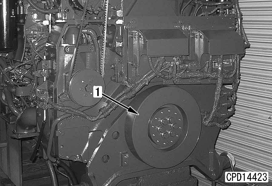
2.Remove crankshaft pulley (1). [*1]
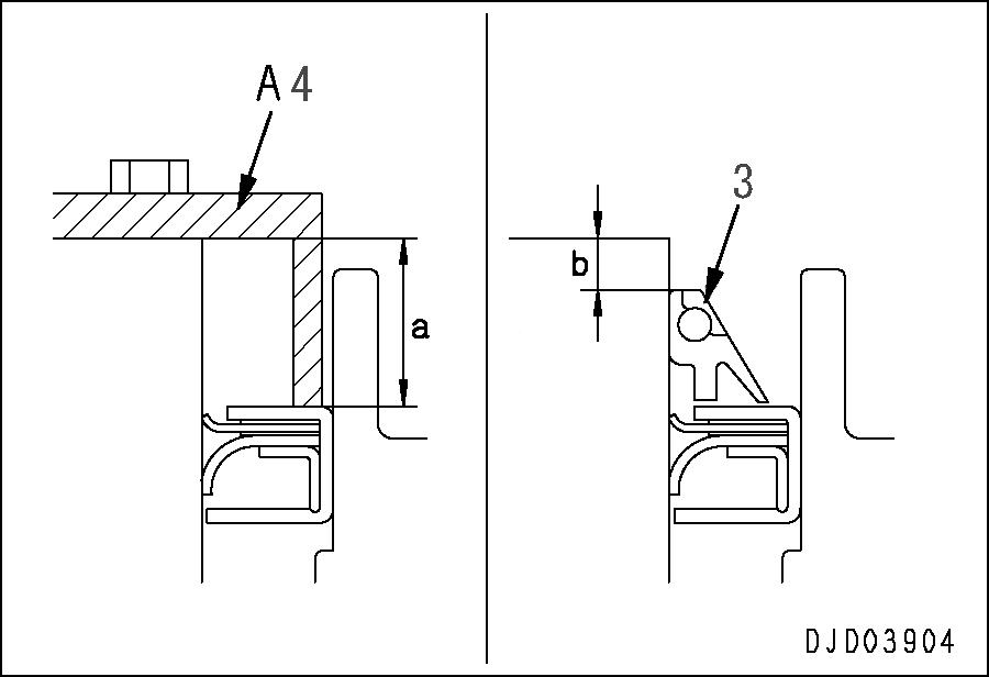
3rd step: 744.8 ± 19.6 Nm {76 ± 2 kgm} [*2] a Do as follows according to the wear of the crankshaft seal contact surface.
1)When crankshaft is a new part or when there is no wear of oil seal contact surface.
1]Press fit by tool A4
2]After press fitting, check mounting dimension (a)
Front seal mounting dimension (a): 17.5 mm
3]Install dust seal (3).
3.Remove
Dust seal mounting dimension (b): approx. 7 mm
D475A, D475ASD-5E0
Installation
1.Using guide bolt, and install flywheel (2).
Special tools
Removal
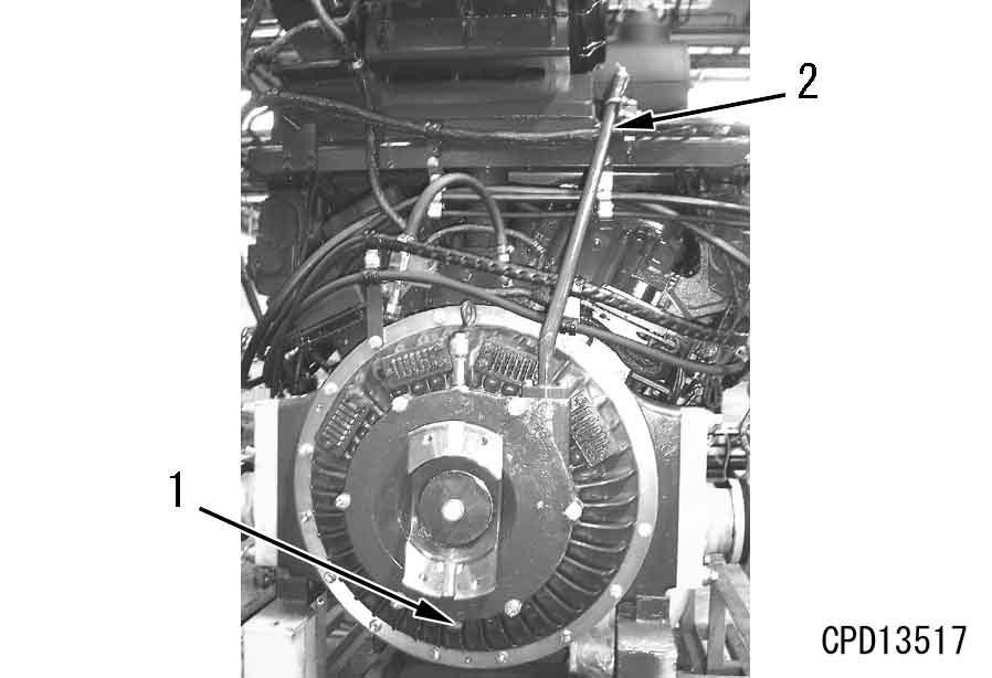
1.Remove damper assembly. For details, see "Removal and installation of damper assembly".
2.Sling with eyebolts [1] (M16, P=2), remove mounting bolts (1), screw in forcing screws [2] (M12, P=1.75), then remove flywheel (2).
4 Flywheel: 140 kg
2.Secure flywheel (2) and housing with plate [3].
3.Remove rear seal (3).[*1] a Tighten the mounting bolts in the order shown in the diagram below.
3 Flywheel mounting bolt:
1st step: 98 ± 19.6 Nm {10 ± 2 kgm}
2nd step: 294 ± 19.6 Nm {30 ± 2 kgm}
3rd step: 539 ± 19.6 Nm {55 ± 2 kgm} q Face runout: Max. 0.30 mm q Radial runout: Max. 0.30 mm
3.After installing flywheel, use dial gauge [4] to measure radial and face runout of flywheel.
[*1] a Do as follows according to the wear of the crankshaft seal contact surface.
1)When crankshaft is a new part or when there is no wear of oil seal contact surface.
1]Press fit by tool A5.
2]After press fitting, check mounting dimension (a)
Front seal mounting dimension (a): 18.5 mm
D475A-5E0
D475ASD-5E0
Power train, Part 1
Removal and installation of damper assembly
Removal
1.Remove hood assembly. For details, see Removal and installation of hood assembly.
2.Open underguard (3rd from front of machine).
3.Remove drain plug (1) and drain damper oil.
6 Damper case: Approx. 2.2 l
4.Remove dipstick and dipstick guide (2).
6.Remove holder (4) and coupling (5).[*2] k Install guide bolts (12 mm, P = 1.75, l = 100) in 2 mounting bolt holes in the top of the damper cover so that the damper cover does not come out suddenly.
7.Remove retainer (6).
8.Sling damper cover (7), then use forcing screw [1] (12mm, P=1.75) to remove damper cover.
4 Damper cover: 50 kg
5.Sling universal joint (3), then remove mounting bolts, and lift off. [*1]
4 Universal joint: 65 kg
9.Sling damper assembly (8), then using guide bolt [2] (16 mm, P = 2.0) and nut [3], loosen nut slowly so that damper assembly does not come out suddenly, then remove.
4 Damper assembly: 85 kg
Installation q Carry out installation in the reverse order to removal.
[*1]
3 Universal joint mounting bolt: 156.8 – 196 Nm {16 – 20 kgm}
[*2]
2 Holder mounting bolt thread: Thread tightener (LT-2)
3 Holder mounting bolt: 490 – 607.6 Nm {50 – 62 kgm} q Refilling with oil (damper case)
Add oil through the oil filler to the specified level, and run the engine to circulate the oil through the system. Then check the oil level again.
D475A, D475ASD-5E0
Disassembly and assembly of damper assembly
Disassembly
1.Remove bolt (1), then remove flange (2).
2.Remove seal (3).
3.Remove shaft (4).
4.Remove rubber (5).
5.Remove flange (6) from body (7).
6.Remove seal (8).
7.Remove bearing (9).
Assembly a Install the seal with the lip facing the inside as shown in the diagram.
1.Using push tool, press fit bearing (9).
2 Flywheel pilot portion: Grease (G2-U) a Fill 50% (approx. 55 g) of clearance (a).
2.Install seal (8) to flange (6), and seal (3) to flange (2).
Disassembly of damper cover assembly
8.Remove bearing (10) and seal (11) from cover (12).
9.Remove oil seal (13) from retainer (14).
3.Align the bolt holes with body (7), then install flange (6).
2 Flange mating surface:
Gasket sealant (LG-4) a Check that there are no dents, rust, oil or grease, or water on the mating surface, then coat both the flange and body surfaces with gasket sealant. a Coat with a thickness of about 0.1 – 0.2 mm, leave to dry for 2 – 3 minutes, then tighten. a When assembling the rubber, coat the whole surface of the rubber, the outside circumference of the shaft, and the inside circumference of the body with grease (G2-LI). a After assembling the rubber, fill approx. 50% (approx. 400 g) of the space ((b) portion: 16 places) between the shaft and body with grease (G2-LI).
4.Set shaft (4) to flange and body assembly in position.
5.Assemble rubber (5).
7.Tighten bolt (1).
6.Install flange (2).
2 Flange mating surface: Gasket sealant (LG-4) a Check that there are no dents, rust, oil or grease, or water on the mating surface, then coat both the flange and body surfaces with gasket sealant. a Coat with a thickness of about 0.1 – 0.2 mm, leave to dry for 2 – 3 minutes, then tighten.
Assembly of damper cover assembly
8.Using push tool [1], press fit oil seal (13) to retainer (14).
2 Oil seal press-fitting surface: Gasket sealant (LG-1) a Coat the inside surface of the retainer thinly with gasket sealant and wipe off any sealant that is forced out.
2 Lip of oil seal: Grease (G2-LI)
9.Using push tool [2], press fit bearing (10) to cover (12).
10.Using push tool [1], press fit oil seal (11) to cover (12).
2 Oil seal press-fitting surface: Gasket sealant (LG-1) a Coat the inside surface of the cover thinly with gasket sealant and wipe off any sealant that is forced out.
2 Lip of oil seal: Grease (G2-LI)
Removal and installation of power train unit assembly
Removal
1.Drain oil from hydraulic tank and power train case.
6 Hydraulic tank: Approx. 120 l
6 Power train case: Approx. 150 l
2.Remove floor frame assembly. For details, see "Removal and installation of floor frame assembly".
3.Remove fuel tank assembly. For details, see "Removal and installation of fuel tank assembly".
4.Remove brake rod (1).
5.Disconnect cable (2).
8.Remove hydraulic pump inlet tube coupling (5) and hydraulic tank side coupling (6), and remove tube (7).
9.Disconnect fan motor hose (8).
10.Disconnect hoses (9) and (10).
11.Disconnect steering hose (11).
12.Disconnect hoses (12) and (13).
6.Disconnect lubrication hose (3).
7.Disconnect fan motor pump tube coupling (4).
13.Remove hydraulic pump inlet tube (14).
14.Disconnect hydraulic pump PPC hoses (15) and (16).
15.Disconnect hydraulic pump outlet hoses (17) and (18).
16.Disconnect hydraulic PPC hoses (19) and (20).
19.Remove universal joint (23).[*1]
4 Universal joint: 65 kg
17.Disconnect wiring connector (21) (PL1, PL2, PL3).
20.Remove front mount bolt (24).[*2]
21.Remove rear mount bolt (25), then remove mount cap (26).[*3]
4 Mount cap: 30 kg
18.Disconnect hose (22), then disconnect clamp (1 place) on top of steering case.
22.Remove housing clip (27), and move flange (28) towards final drive end.[*4] a Pull out the shaft with forcing screws [2]. a If the shaft will not come out, set jack [3] on the ground and push the shoe grouser up, then move the sprocket to the front or rear to a position where the shaft will come out, and remove the shaft.
23.Using forcing screws [1], remove cover (29).
24.Remove shaft (30).
Installation q Carry out installation in the reverse order to removal.
[*1]
3 Universal joint mounting bolt: 156.8 – 196 Nm {16 – 20 kgm}
[*2]
3 Front mount bolt: 1,519 – 1,911 Nm {155 – 195 kgm}
25.Lift off power train unit assembly (31).[*5]
4 Power train unit assembly: 5,500 kg
[*3]
3 Rear mount bolt: 823.2 – 1,029 Nm {84 – 105 kgm}
[*4] a Check that the housing clip is fitted securely in the flange.
3 Housing clip: 4.9 – 8.8 Nm {0.5 – 0.9 kgm}
[*5] a When installing the power train unit assembly, pay attention to the mating surface of the coupling, and be careful not to damage the seal of the rear mount coupling. q Refilling with oil
Add oil through the oil filler to the specified level, and run the engine to circulate the oil through the system. Then check the oil level again.
5 Power train case: Approx. 210 l
5 Hydraulic tank: Approx. 140 l
D475A, D475ASD-5E0
Removal and installation of PTO, torque converter assembly
Removal a Set blocks under the front of the oil pan, transmission rear case, and steering case.
1.Remove power train unit assembly. For details, see "Removal and installation of power train unit assembly".
2.Raise power train unit assembly (1) and set on block.
6.Sling filter assembly (6), then remove.
4 Transmission filter assembly: 40 kg
4 Torque converter, transmission lubrication filter assembly: Approx. 80 kg a Before removing the pressure detection hoses, mark them with tags to prevent any mistake in the mounting position when installing. k Sling the power train pump, then remove together with the strainer.
4.Disconnect central pressure detection hose (3), then remove together with central pressure detection bracket (4).
7.Remove power train pump (7) and strainer assembly (8).
4 Power train pump, strainer assembly: 100 kg
8.Lift off mount bracket (9).[*2]
4 Mount bracket: 70 kg k Sling the scavenging pump, then remove the mounting bolts.
9.Remove tube (10) and scavenging pump (11).
4 Scavenging pump: 24 kg
10.Remove hose (12).
11.Remove gauge guide (13).
14.Remove PTO and torque converter assembly (19).[*3] k Sling the PTO and torque converter assembly, then remove the mounting bolts. a Using a lever block, lift off the PTO and torque converter assembly horizontally.
4 PTO, torque converter assembly: 830 kg
12.Removal of fan pump
1)Remove tube (14).
2)Remove wire (15).
3)Remove connector (16).
4)Lift off pump assembly (17).
4 Fan pump assembly: 75 kg
Installation q Carry out installation in the reverse order to removal.
[*1]
[*2] k Bend the cotter pin securely.
2 PTO boss rotating portion: Grease (G2-LI) a Remove the block under the oil pan, sling the oil pan, then remove the mounting bolts and disconnect the oil pan.
13.Remove oil pan (18).
4 Oil pan: 120 kg
[*3] a Using a lever block, raise the PTO and torque converter assembly horizontally, align it with the spline of the shaft at the steering case end, then install.
D475A, D475ASD-5E0
Disconnection and connection of PTO, torque converter assembly
Special tools
790-413-1010Bracket t 1
790-501-5000Repair stand t 1
Disconnection
1.Set PTO and torque converter assembly (1) to tool C
5.Remove oil seal (6).[*2] a Remove snap ring (8), then remove the spacer. a Remove snap ring (4), then remove the cap.
6.Remove spacer (7).
2.Remove coupling assembly (2).
3.Remove cap (3).
4.Remove retainer assembly (5). [*1] a Using forcing screws, remove the cover, retainer assembly, and shims. a Check the number and thickness of the shims, and keep in a safe place. a Using eyebolts [1], raise the PTO assembly, then disconnect it from the torque converter assembly.
7.Remove PTO assembly (9) and torque converter assembly (10).
4 PTO, torque converter assembly: 830 kg
Connection q Carry out connection in the reverse order to disconnection.
[*1] a Measure clearance (a) at four points ( A , B , C , D ) around the circumference, and take the average as clearance (a). q (a) – (0 to 0.05 mm) a Shim thickness: 0.15 mm, 0.20 mm, 0.50 mm
Adjust the clearance of the taper roller bearing as follows.
1)Assemble the oil seal to the retainer assembly, then install the cover, and tighten to 9.8 Nm {1 kgm}.
2)Using a clearance gauge, measure clearance (a) between the retainer and the housing.
3)Measure shim thickness.
4)Assemble the selected thickness of shim, and tighten the retainer assembly to the specified torque.
3 Retainer mounting bolt: 58.8 – 73.5 Nm {6 – 7.5 kgm} a Assemble the shim as shown in the diagram below so that it does not come at position (b) of the retainer removal tap.
[*2]
2 Outer circumference of oil seal: Gasket sealant (LG-5)
Disassembly and assembly of torque converter assembly
Special tools
790-413-1010Bracket t 1
790-501-5000Repair stand t 1
Disassembly q Set the torque converter assembly to tool C a Disassemble the lockup clutch and drive case assembly as follows.
2)Using eyebolts [1], remove lockup clutch and drive case assembly (4).
1]Remove seal ring (5), and using forcing screws [2], remove input shaft (6).
1.Torque converter valve assembly
Remove torque converter valve assembly (1).
2.Draining oil
Remove 2 drain plugs (2), and drain oil from pump case. a After draining the oil, tighten the plugs.
3.Lockup clutch, drive case assembly a When the assembly is removed, the piston will fall out, so support it by hand when removing. a After removing the discs and plates, keep them in a flat place to prevent them from becoming distorted.
1)Leaving 2 mounting bolts (3) in position, remove mounting bolts, then place input shaft side on top and remove remaining mounting bolts.
2]Remove snap ring (7), then remove plate (8).
3]Set clutch housing side at bottom, and using forcing screws [3], remove turbine (9).
4]Set clutch housing at top, then using eyebolts [4], remove housing and piston assembly (10).
5]Remove piston (11) from housing (12).
9]Remove 3 discs (16) and 2 plates (17) from drive case (18).
6]Remove seal ring (13) from piston.
7]Remove seal ring (14) from housing.
4.Stator assembly
1)Remove snap ring (19), then remove stator assembly (20).
2)Disassemble stator assembly as follows.
1]Remove snap ring (21), then remove race (22) from stator (23).
8]Using push tool [5], remove bearing (15) from housing.
2]Remove snap ring (24) from stator (23).
5.Pump assembly
1)Remove snap ring (25).
2)Remove pump assembly (26).
3)Disassemble pump assembly as follows.
1]Remove retainer (27).
2]Remove bearing and guide assembly (28) from pump (29).
9.Pin
Remove pin (37).
3]Remove bearing outer race (30) from guide (31).
6.Stator
Set stator clutch housing at top and remove stator clutch housing (32).
10.Inner gear
Remove snap ring (38), then remove inner gear (39).
11.Piston
1)Remove piston (40) from case (41).
7.Spring
Remove spring (33).
8.Springs, discs, plate a After removing the discs and plates, keep them in a flat place to prevent them from becoming distorted.
Remove springs (34), 2 discs (35), and 1 plate (36).
2)Remove seal ring (42) from piston.
3)Remove seal ring (43) from case.
12.Stator shaft assembly
1)Tap stator shaft assembly (44) with a plastic hammer, and remove from case (45).
2)Disassemble stator shaft assembly as follows.
1]Using push tool [6], remove shaft assembly (46) from stator shaft assembly.
5]Using push tool [7], remove bearing (55), then remove plate (56).
2]Remove snap ring (47), then remove bearing inner race (48), bushing (49), and seal ring (50) from shaft.
3]Remove seal ring (51) from stator shaft (52).
4]Remove snap ring (53), then remove plate (54).
Assembly
a Wash all parts in clean flushing oil (in particular, oil holes, etc.), then dry them, and check for dirt or damage. Coat the sliding surfaces of all parts with engine oil before installing.
q Set case (41) to tool C.
1.Stator shaft assembly
1)Assemble plate (56) to stator shaft (52), and using push tool, press fit bearing (55).
a Put drops (approx. 6 cc) of engine oil (SAE10W-CD or SAE30-CD) on the bearing and rotate about 10 times.
2)Install plate (54), and secure with snap ring (53).
3)Install seal ring (51) to stator shaft (52).
a After installing the seal ring, coat it with grease (G2-LI) to fix it to the shaft securely.
7)Install snap ring (47), and secure inner race.
4)Install seal ring (50) to shaft.
a After installing the seal ring, coat it with grease (G2-LI) to fix it to the shaft securely.
5)Using push tool [9], press fit bushing (49) to shaft.
a Be careful not to deform the bushing when press fitting.
6)Using push tool [10], press fit inner race (48) to shaft.
8)Tap stator shaft (52) with a plastic hammer and press fit bearing portion to case.
9)Set shaft (46) to stator shaft, then using push tool, press fit bearing portion.
10)Turn over case and tighten mounting bolts of shaft from case end.
2 Mounting bolt: Thread tightener (LT-2)
3 Mounting bolt: 58.8 – 73.5 Nm {6 – 7.5 kgm}
2.Piston
1)Install seal ring (43) to case.
2 Outer circumference of seal ring: Grease (G2-LI) a Be careful to assemble the seal ring facing in the direction shown in the diagram below.
2)Install seal ring (42) to piston.
2 Outer circumference of seal ring: Grease (G2-LI) a Be careful to assemble the seal ring facing in the direction shown in the diagram below.
6.Spring
Install spring (33).
3)Install piston (40) to case (41).
2 Contact surface of seal ring: Grease (G2-LI)
3.Inner gear
Install inner gear (39) and secure with snap ring (38).
7.Stator clutch housing a Check that the springs are fitted securely in the holes in the housing and piston.
Install stator clutch housing (32).
2 Mounting bolt: Thread tightener (LT-2)
3 Mounting bolt: 98 – 122.5 Nm {10 – 12.5 kgm}
8.Pump assembly a Put drops (approx. 6 cc) of engine oil (SAE10W-CD or SAE30-CD) on the bearing and rotate about 10 times.
1)Assemble pump assembly as follows.
1]Using push tool, press fit bearing outer race (30) to guide (31).
4.Pin Install pin (37).
5.Plate, discs, springs
Install 1 plate (36), 2 discs (35), and springs (34).
2]Set bearing and guide assembly (28) to pump (29), then tap with a plastic hammer and press fit bearing portion.
3]Install retainer (27).
2 Mounting bolt: Thread tightener (LT-2)
3 Mounting bolt: 58.8 – 74.5 Nm {6 – 7.5 kgm} a When installing the pump, be careful not to damage the seal ring assembled to the shaft.
2)Install pump assembly (26).
3)Install snap ring (25).
10.Lock-up clutch, drive case assembly
1)Assemble lock-up clutch and drive case assembly as follows.
1]Set turbine (9) to block [11], and set drive case (18) to turbine.
9.Stator assembly
1)Assemble stator assembly as follows.
1]Install snap ring (24) to stator (23).
2]Install 3 discs (16) and 2 plates (17).
2]Assemble race (22) to stator (23), and secure with snap ring (21).
2)Install stator assembly (20) to stator shaft, and secure with snap ring (19).
3]Install seal ring (14) to housing.
2 Outer circumference of seal ring: Grease (G2-LI)
4]Install seal ring (13) to piston.
2 Outer circumference of seal ring: Grease (G2-LI)
5]Install piston (11) to housing (12).
2 Contact surface of seal ring: Grease (G2-LI) a When installing, be careful not to damage the seal ring. a Support the piston assembly by hand to prevent it from falling out when installing.
6]Using eyebolts [4], install housing and piston assembly (10).
2 Mounting bolt: Thread tightener (LT-2)
3 Mounting bolt: 98 – 122.5 Nm {10 – 12.5 kgm} a Align the positions of the turbine oil groove ( mark) and drain plug (2) when installing. a Put drops (approx. 6 cc) of engine oil (SAE10W-CD or SAE30-CD) on the bearing and rotate about 10 times.
2)Using eyebolt [1], install lock-up clutch and drive case assembly (4).
7]Using push tool, press fit bearing (15).
8]Install plate (8), and secure with snap ring (7).
9]Install input shaft (6).
2 Mounting bolt: Thread tightener (LT-2)
3 Mounting bolt: 156.8 – 196 Nm {16 – 20 kgm}
10]Install 2 seal rings (5).
3)Tighten mounting bolts (3). a Check that drain plug (2) is tightened.
3 Mounting bolt: 49 – 58.8 Nm {5 – 6 kgm}
3 Drain plug: 9.8 – 12.7 Nm {1 – 1.3 kgm}
D475A, D475ASD-5E0
11.Torque converter valve assembly
Install torque converter valve assembly (1). a Tighten the mounting bolts uniformly in turn and be careful not to tighten them unevenly.
3 Mounting bolt: 43.1 – 53.9 Nm {4.4 – 5.5 kgm}
Disassembly and assembly of PTO assembly
Disassembly
1.PTO lubrication tube a Remove the 3 lubrication tubes on the opposite side also, set the torque converter end at the bottom, then lower.
Sling PTO assembly and remove lubrication tube (1).
3)Using puller [2], remove bearings (5) and (6) from gear (7).
2.Hydraulic pump gear assembly
1)Using forcing screws [1], pull out cover assembly (2) and lift off.
2)Using puller [2], remove gear assembly (3) from cover (4).
3.Power train and PPC pump gear assembly
1)Using forcing screw [1], pull out cover assembly (8) and lift off.
2)Using puller [2], remove bearing (9).
3)Remove gear (10).
4)Using push tool [3], remove boss (11) and bearing (12) from cover.
5)Using forcing screw [4], remove bearing (12) from boss (11).
4.Scavenging drive gear
Remove snap ring (13) from bottom of PTO case, then remove gear (14).
5.Shaft assembly
1)Remove plate (15) of idler gear.
6.Idler gear assembly
1)Remove idler gear assembly (19) and bearing (20) from bottom of PTO case.
2)Remove outer race (21).
2)Turn over PTO case, then using forcing screw [1], remove shaft assembly (16). a The bearing outer race and key assembly will come out from the bottom of the PTO case, so place a wooden block in position and be careful not to damage the assembly.
3)Remove plug (17), then using forcing screw, push out bearing (18). a After removing the bearing, assemble the plug again in the correct position.
7.PTO case
1)Remove race assembly (24) together with bearing outer race (25).
2)Remove bearing inner races (26) and (27) from race (28).
3)Remove bearing outer race (29).
4)Remove sleeve (30).
Assembly a Clean all parts, and check for dirt or damage. a Check that the snap ring is fitted securely in the groove.
1.Bearing a Put drops (approx. 6 cc) of engine oil (SAE10W-CD or SAE30-CD) on the bearing and rotate about 10 turns.
1)Using push tool, press fit bearing (23) to case.
2)Install snap ring (22).
8.Bearing
1)Remove snap ring (22).
2)Remove bearing (23).
2.PTO case a Install the sleeve with the chamfered inside circumference facing down. a Expand-fit the sleeve.
1)Install sleeve (30) to case.
2)Using push tool, press fit bearing outer race (29).
D475A, D475ASD-5E0
3)Using push tool, press fit bearing inner races (27) and (26) to race (28).
4.Shaft
Assembly
1)Using push tool [6], press fit bearing inner race (18) to shaft.
2)Fit O-ring, align shaft assembly (16) with idler gear, then insert.
4)Install race assembly (24).
2 Internal surface of race: Anti-friction compound (LM-P) a Put drops (approx. 6 cc) of engine oil (SAE10W-CD or SAE30-CD) on the bearing and rotate about 10 turns.
5)Using push tool, press fit bearing outer race (25).
5.Bearing
1)Turn over PTO case, and press fit bearing spacer (31) and bearing inner race (20) to shaft, then tighten mounting bolts of shaft assembly. a Put drops (approx. 6 cc) of engine oil (SAE10W-CD or SAE30-CD) on the bearing, then rotate approx. 10 turns.
3.Idler gear
1)Using push tool [5], press fit bearing outer race (21) to gear (19).
2)Position idler gear to PTO case.
2)Install plate (15).
2 Mounting bolt: Thread tightener (LT-2)
3 Mounting bolt: 98 – 123 Nm {10 – 12.5 kgm}
6.Scavenging drive gear
1)Install gear (14).
2 Spline portion: Grease (G2-LI)
2)Using push tool [8], press fit boss (11) and bearing (12) to cover. a Expand fit the bearing.
2 Boss spline portion: Grease (G2-LI)
3)Install gear (10).
2 Gear spline portion: Grease (G2-LI)
2 Gear mounting bolt: Thread tightener (LT-2)
3 Gear mounting bolt: 98 – 122.6 Nm {10 – 12.5 kgm}
2)Install snap ring (13) from bottom of PTO case.
7.Power train, PPC pump gear assembly
1)Using push tool [7], press fit bearing (12) to boss (11).
4)Using push tool [7], press fit bearing (9) to gear (10).
5)Raise cover assembly (8) and install. a If the cover assembly is stiff and does not enter the case, use a plastic hammer and tap evenly on the side face to install.
D475A, D475ASD-5E0
8.Hydraulic pump gear assembly
1)Using push tool [7], press fit bearings (5) and (6) to gear (7).
9.Lubrication tube
Sling PTO assembly, then install lubrication tube (1).
a Install 3 lubrication tubes also on the opposite side.
3 Mounting bolt:
19.6 – 29.4 Nm {2 – 3 kgm} a Expand fit the bearing. a Set the end where the bearing end face and gear end face are level so that it faces the cover.
2)Using push tool [8], press fit gear assembly (3) to cover (4).
2 Gear spline portion: Grease (G2-LI) a If the cover assembly is stiff and does not enter the case, use a plastic hammer and tap evenly on the side face to install.
3)Fit O-ring, then raise cover assembly (2) and install to case.
Removal and installation of TORQFLOW transmission assembly
Removal q Remove PTO and torque converter assembly. For details, see "Removal and installation of PTO, torque converter assembly".
1.Remove TORQFLOW transmission assembly (1).[*1] k Sling the transmission assembly, then remove the mounting bolts. a Using a lever block, raise the transmission horizontally, then remove from the steering.
4 TORQFLOW transmission assembly: 1,330 kg
Installation q Carry out installation in the reverse order to removal.
[*1] a Using a lever block, sling transmission assembly (1) horizontally, align with spline of shaft at steering case end, then install.
Disassembly and assembly of TORQFLOW transmission assembly
Special tools
790-413-1010Bracket t 1
790-501-5000Repair stand t 1
799-301-1600Oil leak tester t 1
Disassembly q Set the transmission assembly on the block.
1.Control valve assembly
1)Remove cover (1).
2)Remove control valve assembly (2) together with seat.
3.Transmission case
1)Turn over transmission assembly, and remove plate (10).
2)Using eyebolts, remove transmission case (11).
2.Sleeve
1)Remove plug (8).
2)Using eyebolts [1], pull out sleeve (9).
4.Housing
1)Remove 17 tie bolts (12).
2)Using eyebolts, remove housing (13).
3)Remove seal ring (14) from housing.
5.Spring
Remove spring (15).
6.Discs, plates, springs a Keep the discs and plates in a flat place to prevent them from becoming deformed.
Remove discs (16), plates (17), and springs (18) in turn.
7.No. 1 ring gear
Remove ring gear (19).
11.Sleeve, guide pin
1)Remove sleeve (27).
2)Remove guide pin (28).
8.No. 1 housing, piston
1)Using eyebolts, remove No. 1 housing and piston assembly (20).
2)Remove piston (22) from housing (21).
12.Shaft, No. 1, 2, 3 carrier assembly
Using eyebolts, remove No. 1, 2, and 3 carrier assembly (29).
4 Shaft, No. 1, 2, 3 carrier assembly: 200 kg
1)Disassemble the shaft and carrier assembly as follows.
1]Remove snap ring (130), then remove sun gear (30).
2]Using eyebolts, remove shaft and No. 1 carrier assembly (31) from No. 2 and 3 carrier assembly (32).
9.Spring
Remove spring (23).
10.Discs, plates, springs a Keep the discs and plates in a flat place to prevent them from becoming deformed.
Remove discs (24), plates (25), and springs (26) in turn.
D475A, D475ASD-5E0
2)Disassemble the shaft and No. 1 carrier assembly as follows.
1]Raise the assembly, then using forcing screw [2], remove shaft and cage assembly (33).
2]Using plastic hammer, remove cage assembly (34), spacer (35), and bearing (36).
3]Remove seal ring (37) from cage assembly.
4]Remove seal ring (38) from cage.
5]Remove seal ring (40) from shaft (39).
3)Disassemble the No. 2, No.3 carrier assembly as follows.
1]Remove sun gear (48).
2]Using eyebolts, remove plate and gear assembly (49).
6]Remove shaft (42), ball (43), thrust washer (44), gear (45), and bearing (46) from No. 1 carrier assembly (41).
7]Remove seal rings (47) and (131).
3]Remove ring (50), and disassemble plate (51) and gear (52).
4]Remove plate (54) from No. 2, 3 carrier assembly (53).
5]Remove seal ring (55) from plate.
6]Remove shaft (56), ball (57), thrust washer (58), gear (59), and bearing (60).
7]Using push tool, remove collar and bearing assembly (61) from carrier.
8]Using push tool, remove bearing (62).
15.No. 3 piston
Remove No. 3 piston (71).
16.Spring
Remove spring (72).
17.Discs, plates, springs a Keep the discs and plates in a flat place to prevent them from becoming deformed.
Remove discs (73), plates (74), and springs (75) in turn.
9]Using puller and push tool, remove bearing (63) and spacer (64) from collar (65).
10]Remove seal ring (66).
18.Seat
Remove seat (76).
19.No. 3 housing
Using eyebolts, remove No. 3 housing (77).
4 No. 3 housing: 55 kg
20.No. 4 piston
Remove No. 4 piston (78).
13.No. 2 ring gear
Remove ring gear (67).
14.No. 2 housing, piston
1)Using eyebolts, remove No. 2 housing and piston assembly (68).
4 No. 2 housing, piston: 80 kg
2)Remove piston (70) from housing (69).
21.Spring
Remove spring (79).
22.Discs, plates, springs a Keep the discs and plates in a flat place to prevent them from becoming deformed.
Remove discs (80), plates (81), and springs (82) in turn.
23.Guide pin
Remove guide pin (83).
24.Sun gear
Remove snap ring (132), then remove sun gear (84).
26.No. 3 ring gear
1)Remove ring gear (91).
2)Remove ring (92) from ring gear.
25.Plate, bearing
1)Using eyebolts, remove plate and bearing assembly (85).
2)Using push tool [3], remove bearing (87) from plate (86).
3)Using puller [4] and push tool [3], remove bearing (88).
4)Using push tool, remove bearing (90) from collar (89).
27.Plate, ring gear
1)Using forcing screws, remove plate and ring gear assembly (93).
2)Remove ring gear (94).
28.No. 4 carrier, No. 5 clutch assembly
Using eyebolts, remove No. 4 carrier and No. 5 clutch assembly (95).
1)Disassemble the No. 4 carrier and No. 5 clutch assembly as follows.
1]Remove 2 mounting bolts, then install guide bolts.
2]Remove remaining mounting bolts, then loosen guide bolts [5] slowly, and remove No. 4 carrier assembly (96) from No. 5 clutch assembly (97).
4 No. 4 carrier assembly, No. 5 clutch assembly: 160 kg
3]Remove shaft (98), ball (99), thrust washer (100), gear (101), and bearing (102).
9]Remove piston (112) from No. 5 housing (111).
10]Remove spacer (113) and seal ring (114) from No. 5 housing.
29.Shaft a Keep the discs and plates in a flat place to prevent them from becoming deformed.
Remove shaft (115).
4]Remove spring (103) and pin (104).
5]Remove discs (105), plates (106), and springs (107).
6]Remove guide pin (108).
7]Remove inner gear (109).
8]Remove seal ring (110) from inner gear.
30.Shaft assembly
Set case so that shaft is at bottom, then using eyebolts, remove shaft assembly (117) from case (116).
4 Shaft assembly: 80 kg
1)Disassemble the shaft assembly as follows.
1]Remove snap ring, then using eyebolts, sling shaft assembly, knock out bearing portion, and remove shaft assembly (118).
2]Remove cage (119).
3]Using stand [6], remove bearing (120).
9]Remove snap ring (135), then remove boss and bearing (127).
10]Remove snap ring (136), then using push tool, remove bearing (129) from boss (128).
4]Remove snap ring (134), then remove bearing (121) from cage (133).
5]Remove seal ring (122).
6]Remove cover (123).
Assembly
a Wash all parts in clean flushing oil (in particular, oil holes, etc.), then dry them, and check for dirt or damage. Coat the sliding surfaces of all parts with engine oil before installing.
a Set the seal ring facing its pressure receiving side for the housing, then coat with grease (G2-LI) and install uniformly so that it is positioned correctly.
a Align the notches of the oil groove when installing the discs.
7]Remove bearing (124).
8]Remove seal ring (126).
1.Shaft assembly
1)Assemble the shaft assembly as follows.
1]Install seal ring (126).
2]Using push tool, install baring (124).
8]Using eyebolts, sling shaft assembly (118), then press fit bearing, and secure with snap ring.
2)Set the case so that the side for installing the steering assembly is at the top, then using eyebolts, install shaft assembly (117) in the case (116).
3]Install cover (123).
4]Install seal ring (122).
5]Install bearing (121) to cage (133) and secure with snap ring (134).
2.No. 4 carrier, No. 5 clutch assembly
1)Assemble the No. 4 carrier and No. 5 clutch assembly as follows.
1]Using push tool, install spacer (113) to No. 5 housing (111).
2]Install seal ring (114).
3]Install piston assembly (112) to No. 5 housing (111).
6]Using push tool, press fit bearing (120).
7]Fit seal ring and install cage (119).
4]Install seal ring (110) to inner gear.
5]Install inner gear (109).
6]Install guide pin (108).
7]Install springs (107), plates (106), and discs (105) in turn.
8]Install pin (104) and spring (103). a Free length of spring: 103.5 mm
11]Set No. 4 carrier assembly (96) to No. 5 clutch assembly (97), and using 2 guide bolts [5], compress spring, then tighten mounting bolts. a Check that the spring is fitted securely in the hole of the housing, then tighten the mounting bolts.
2 Mounting bolt: Thread tightener (LT-2)
3 Mounting bolt: 157 – 196 Nm {16 – 20 kgm}
9]Assemble bearing (102) in gear (101), and fit thrust washers (100) to both sides, then set in position in carrier.
10]Assemble ball (99) to shaft (98), and push shaft into carrier.
2)Using eyebolts, install No. 4 carrier and No. 5 clutch assembly (95).
3.Plate, ring gear a To ensure that the plate is fitted facing in the correct direction, check the bolt hole, then knock in the dowel pin portion with a plastic hammer until there is no clearance at the mating surface.
1)Using eyebolts, align with dowel pin, then install plate (93).
2)Install ring gear (94).
4.No. 3 ring gear
1)Install ring gear (92).
2)Install No. 3 ring gear (91).
5.Plate, bearing a Set the large protrusion of the bearing assembly on top as shown in the diagram below, and install to the plate.
1)Using push tool, press fit bearing (90) in collar (89).
2)Using push tool, press fit bearing (88).
3)Using push tool, press fit bearing (87) in plate (86).
4)Using eyebolts, install plate and bearing assembly (85).
6.Sun gear
Install sun gear (84), and secure with snap ring (132).
7.Guide pin
Install guide pin (83).
8.Discs, plates, springs
Install springs (82), plates (81), and discs (80) in turn.
9.Spring
Install spring (79). a Free length of spring: 81.7 mm
10.No. 4 piston
Fit seal ring and install No. 4 piston (78).
11.No. 3 housing
Using eyebolts, fit seal ring and install No. 3 housing (77).
12.Seat Install seat (76).
13.Discs, plates, springs
Install springs (75), plates (74), and discs (73) in turn.
14.Spring
Install spring (72). a Free length of spring: 84 mm
15.No. 3 piston
Fit seal ring and install No. 3 piston (71).
17.No. 2 ring gear
Install ring gear (67).
16.No. 2 housing, piston a Check that the spring is fitted securely in the hole of the housing.
1)Fit seal ring, and install piston (70) to housing (69).
2)Using eyebolts, install No. 2 housing and piston (68).
18.Shaft, No. 1, 2, 3 carrier assembly
1)Assemble the No. 2, No. 3 carrier as follows.
1]Install seal ring (66) to carrier.
2]Using push tool, press fit spacer (64) and bearing (63) in collar (65).
3]Using push tool, press fit bearing (62).
4]Using push tool, press fit collar and bearing (61) in carrier.
5]Assemble bearing (60) in gear (59), then fit thrust washers (58) to both sides, and set in carrier.
6]Assemble ball (57) to shaft (56), and push shaft into carrier.
2)Assemble the shaft and No. 1 carrier assembly as follows.
1]Install seal rings (47), (131) to carrier.
2]Assemble bearing (46) in gear (45), then fit thrust washers (44) to both sides, and set in carrier.
3]Assemble ball (43) to shaft (42), and push shaft into carrier case (41).
7]Install seal ring (55) to plate.
8]Install plate (54) to No. 2, 3 carrier assembly (53).
9]Set plate (51) to gear (52), and install ring (50).
4]Install seal ring (40) to shaft (39).
5]Install seal ring (38) to cage.
10]Using eyebolts, install plate and gear assembly (49).
11]Install sun gear (48), and secure with snap ring.
6]Using push tool, press fit bearing (37) in cage.
7]Press fit bearing (36) in shaft.
8]Set spacer (35) to bearing and cage assembly (34), and press fit shaft (39).
2]Set carrier assembly on its side, then install sun gear (30), and secure with snap ring (130).
Using eyebolts, install shaft and No. 1, 2, 3 carrier assembly (29) to housing.
9]Using eyebolts, install shaft and cage assembly (33).
3)Assemble the shaft and carrier assembly as follows.
1]Using eyebolts, install shaft and No. 1 carrier assembly (31) to No. 2, 3 carrier assembly (32). a Align the sun gear with the tooth face of the planetary gear, and tap with a plastic hammer to install.
19.Sleeve, guide pin
1)Install guide pin (28).
2)Install sleeve (27).
20.Discs, plates, springs
Install springs (26), plates (25), and discs (24) in turn.
21.Spring Install spring (23). a Free length of spring: 112 mm
22.No. 1 housing, piston
1)Fit seal ring and install piston (22) to housing (21).
2)Using eyebolts, install No. 1 housing and piston (20).
a Check that the spring is fitted securely in the hole of the housing.
26.Housing
1)Install seal ring (14) to housing.
2)Using eyebolts, set housing (13) in position.
3)Tighten 17 tie bolts (12) in turn.
3 Tie bolts: 353 – 392 Nm {36 – 40 kgm}
23.No. 1 ring gear
Install ring gear (19).
24.Discs, plates, springs. Install springs (18), plates (17), and discs (16) in turn.
25.Spring Install spring (15). a Free length of spring: 112 mm
27.Checking piston stroke
Using tool D, check each piston stroke. a Air pressure: 0.5 – 0.6 MPa {5 – 6 kg/cm2} Unit: mm
28.Transmission case
1)Using eyebolts, install transmission case (11).
2)Install plate (10).
2)Using push tool, install bearing (129) to boss (128), and secure with snap ring (136).
3)Install boss and bearing assembly (127) to output shaft, and secure with snap ring (135).
a Install the bearing slowly and be careful that shaft (115) is mated with the lock portion of boss (128).
29.Rotation detection shaft
1)Set case so that valve mounting surface is at top, then insert rotation detection shaft (115) from output end.
a Check that the tip of the shaft is mated with the lock portion of its mating boss.
30.Sleeve
1)Install sleeve (9).
2)Install plug (8).
31.Control valve assembly
1)Install control valve assembly (2) together with seat.
2)Install cover (1).
D475A-5E0
Power train, Part 2
Disassembly and assembly of steering case assembly
Special tools
Disassembly
1.Steering rod bracket
1)Remove cover (1).
2)Remove tube (2).
3)Remove brake rod bracket (20).
2.Clutch, brake assembly a Remove the clutch and brake assembly on the opposite side in the same way. When pulling out the clutch and brake assembly, be careful not to damage the discs and plates.
Using tool E1, sling clutch and brake assembly, then remove mounting bolts, and remove clutch and brake assembly (3).
4)Remove transmission output shaft speed sensor (75) and flange (76) together.
3.Shafts
Remove left and right shafts (4).
4.Lubrication tube
Remove lubrication tubes (5).
5.Pipes, steering valve
1)Remove left and right pipes (6).
2)Remove pipe (7).
7.Transfer and gear housing assembly
1)Install a guide bolt and tighten forcing screws [1] to remove housing assembly (10).
3)Remove steering valve assembly (21) with seat.
2)Disassemble the transfer and gear housing assembly according to the following procedure.
1]Set the transfer and gear housing assembly on the block.
2]Take out lubrication tube (51).
6.Input shaft
1)Remove cage assembly (8).
2)Remove snap ring, and pull out input shaft (9) from case.
D475A, D475ASD-5E0 a Check the quantity and thickness of the inserted shims and then keep them. a Check the quantity and thickness of the inserted shims and then keep them.
3]Reverse the transfer and gear housing assembly and remove lubrication tube (56).
4]Using eyebolts [11], remove pinion housing assembly (57).
10]Remove collar (63) from gear (64).
11]Using push tool [13], remove bearing outer races (65) and (69), bearing inner races (66) and (67), and collar (68).
5]Using forcing screws, remove cover (58).
6]Remove holder (59).
7]Push pinion shaft (60) out of pinion housing assembly (57) with a press.
8]Remove the holder. Using puller [12], remove bearing inner race (61) from pinion shaft (60).
9]Remove cage and bearing assembly (62).
12]Remove the bolts and remove housing (76) from case (78).
13]Remove drive gear and bearing assembly (77).
14]Remove bearing outer race (79) from case (78).
8.Cage a Check the number and thickness of the shims, and keep in a safe place.
1)Turn over so that right cage is at top, then remove bearing cage (11).
15]Remove bearing inner races (81) and (82) from the drive gear.
2)Using eyebolts [2], remove cage (12).
9.Bevel gear, shaft assembly
1)Using eyebolts, remove bevel gear and shaft assembly (13).
16]Remove bearing outer race (70) from housing (76).
17]Remove snap ring (83), and then remove bearing outer race (71) from housing (76).
2)Disassemble the bevel gear and shaft assembly as follows.
1]Pull out reamer bolt, and remove bevel gear (14) from shaft (15).
2]Using puller [3], remove bearings (16) and (17) from shaft.
D475A, D475ASD-5E0
10.Cage a Check the number and thickness of the shims, and keep in a safe place.
1)Turn over steering case, and remove bearing cage (18).
2)Remove outer race (19) from bearing cage.
2.Bevel gear, shaft assembly
1)Assemble bevel gear and shaft as follows.
1]Using tool E2, press fit bearings (17) and (16).
2]Set bevel gear (14) to shaft (15), and tighten reamer bolt.
3 Reamer bolt: 490 – 607.6 Nm {50 – 62 kgm}
Assembly a Wash all parts, then dry them, and check for dirt or damage. Coat the sliding surfaces of all parts with engine oil before installing.
1.Cage a Standard shim thickness: 2 mm
1)Using push tool, press fit outer race (19).
2)Assemble shim, and install bearing cage (18).
3 Mounting bolt: 245 – 308.7 Nm {25 – 31.5 kgm}
2)Using eyebolts, install bevel gear and shaft assembly (13).
3.Cage
1)Using eyebolts [2], install cage (12).
3 Mounting bolt: 245 – 308.7 Nm {25 – 31.5 kgm} a Standard shim thickness: 2 mm
2)Assemble shim, and install bearing cage (11).
3 Mounting bolt: 245 – 308.7 Nm {25 – 31.5 kgm}
4.Adjusting preload a Measure while the bevel pinion is not engaged. a Standard rotating torque: 9.8 – 11.8 Nm {1.0 – 1.2 kgm} q Rotating force at outside of bevel gear: 51.0 – 61.8 Nm {5.2 – 6.3 kgm}
Rotate bevel gear 10 – 20 turns, and fit pushpull scale [4] to tip of teeth, then measure rotating torque of bevel gear shaft.
3]Using the push tool, press fit bearing inner races (81) and (82).
5.Transfer and gear housing assembly
1)Assemble the transfer and gear housing assembly according to the following procedure.
1]Using the push tool, press fit bearing outer race (71) on the drive gear side and install snap ring (83).
2]Press fit bearing outer race (70) on the pinion side to housing (76).
4]Using the push tool, press fit bearing outer race (79) to case (78).
5]Install drive gear and bearing assembly (77) to the case.
6]Install housing (76), matching it to the dowel pin, and tighten the bolts.
3 Mounting bolt: 277 ± 32 Nm {28.3 ± 3.2 kgm}
7]Using push tool [18], press fit inner race (61) to pinion shaft (60).
8]Install the holder.
2 Holder mounting bolt: Adhesive (LT-2)
3 Holder mounting bolt: 276.85 ± 31.85 Nm {28.25 ± 3.25 kgm}
9]Install pinion gear (64) and collar (63) to the pinion shaft.
12]Tighten the mounting bolts of cover (58) temporarily in the following order.
3 Mounting bolt: 49 Nm {5 kgm}
10]Using push tool [19], press fit cage and bearing assembly (62).
11]Install holder (59).
2 Holder mounting bolt: Adhesive (LT-2)
3 Holder mounting bolt: 276.85 ± 31.85 Nm {28.25 ± 3.25 kgm}
13]Loosen the mounting bolts and tighten them again temporarily in the above order.
3 Mounting bolt: 49 Nm {5 kgm}
14]Check clearance (A) between the cover and cage and adjust it to the following range with the shims. a Clearance (A): 0.05 – 0.15 mm a Check that the dispersion of the clearance is 0.05 mm or less through the periphery and the bearing is press fitted perfectly and is not leaning.
15]Tighten the mounting bolts of cover (58) permanently in the following order.
3 Mounting bolt: 66.15 ± 7.35 Nm {6.75 ± 0.75 kgm}
2)Install guide bolt [5] to the steering case and install housing assembly (10).
3 Mounting bolt: 245 – 308.7 Nm {25 – 31.5 kgm}
16]Install the shim to pinion housing assembly (57). Using eyebolts [11], install pinion housing assembly (57). a Standard shim thickness: 2 mm
17]Install lubrication tube (56).
6.Adjusting tooth contact, backlash
1)Adjusting backlash a Standard value for backlash: 0.3 – 0.4 mm a Measure at a minimum of 3 points on diagonally opposite sides.
Put the probe of dial gauge [6] in contact with the tip of the bevel gear teeth at right angles. Hold the bevel pinion in position, and read the measurement when the bevel gear is moved forward and backward.
18]Install lubrication tube (51) and block as a unit.
Adjusting
If correct backlash pattern is not obtained from the result of inspection, adjust as follows.
1]If backlash is too small: Adjust the shim thickness at the bevel pinion end to move the bevel pinion in direction (A), or adjust the shim thickness at the bearing cage of the bevel gear shaft to move the bevel gear in direction (B).
2)Adjusting tooth contact Testing
1]Coat the tooth face of the bevel pinion lightly with red lead (minimum). Rotate the bevel gear in both the forward and reverse directions, and inspect the pattern left on the teeth.
2]The standard tooth contact should be as follows: (from small end of pinion) a)Width of tooth contact: 30 – 50% b)Center of tooth contact: 20 – 40% a It must be within the standard value when preload is given to the taper roller bearing which is supporting the bevel gear, and only the bevel pinion is meshed, with no load. a The tooth contact should be in the center of the tooth height and there should be no strong contact at the root of the teeth. The contact should be in about the same position when the gear is rotated in forward or reverse. a When adjusting the shim thickness at the bearing cage of the bevel gear shaft, do not change the preload of the bearing. Adjust by moving shims between the bearing cage and the bevel pinion. Always keep the same total thickness of shims.
2]If backlash is too large: Adjust the shim thickness at the bevel pinion end to move the bevel pinion in direction (A) (the opposite direction from (A) above), or adjust the shim thickness at the bearing cage of the bevel gear shaft to move the bevel gear in direction (B) (the opposite direction from (B) above).
Adjusting
If the result of the inspection shows that the correct tooth contact is not being obtained, adjust again as follows.
1]If bevel pinion is too far from center line of bevel gear.
Contact is at the small end of the convex tooth face of the bevel gear and at the big end of the concave tooth face.
[Correct the tooth contact as follows.] Adjust the thickness of the shims at the bevel pinion to move the bevel pinion in direction (A).
Or adjust the thickness of the shims at the bearing cage of the bevel gear shaft to move the bevel gear in direction (B), then check the tooth contact pattern and backlash again.
2]If bevel pinion is too close to center line of bevel gear.
Contact is at the big end of the convex tooth face of the bevel gear and the small end of the concave tooth face.
[Correct the tooth contact as follows.] Adjust the thickness of the shims at the bevel pinion to move the bevel pinion in direction (A) (the opposite direction from (A) above).
Or adjust the thickness of the shims at the bearing cage of the bevel gear shaft to move the bevel gear in direction (B) (the opposite direction from (B) above), then check the tooth contact pattern and backlash again.
a When adjusting the movement in or out of the bevel gear, do not change the preload of the bearing. Adjust by moving shims between the bearing cage and the bevel pinion. Always keep the same total thickness of shims.
7.Transmission output shaft and input shaft
1)Install the speed sensor and flange according to the following procedure.
1]Install flange (76).
a Remove the speed sensor.
2]Looking at transfer gear (85) through the hole of the flange, check that a tooth of the gear is at the center of the hole.
a If a tooth is not seen, turn the transfer gear to bring a tooth to the center of the hole.
3]Remove locknut (84) from speed sensor (75). Apply gasket sealant to the threaded portion of speed sensor (75) and install speed sensor (75) to flange (76).
a Tighten the speed sensor until its tip touches the transfer gear, and then return it by 1/2 – 1 turn.
2 Threaded portion of speed sensor: Gasket sealant (LG-6)
4]Remove the speed sensor and flange as a unit and tighten locknut (84). a Take care that the speed sensor will not turn when the locknut is tightened.
2 Threaded portion of locknut and its contact surface against flange: Gasket sealant (LG-6)
3 Locknut: 49 – 68.6 Nm {5 – 7 kgm}
5]Install speed sensor (75) and flange (76) as a unit.
2 Flange mounting bolt hole and flange mounting surface: Gasket sealant (LG-6)
6]After installing the speed sensor, rotate the transfer gear slowly and check that the speed sensor does not interfere with the gear.
8.Steering valve and pipe
1)Install steering valve assembly (21) and seat as unit.
2)Install pipe (7).
3)Install left and right pipes (6). a Coat the O-rings thinly with grease (G2LI), and be careful not to damage them when installing.
2)Install input shaft (9) to the case and fix it with the snap ring.
3)Install cage assembly (8).
9.Lubrication tube
Install lubrication tubes (5).
10.Clutch, brake assembly
Using tool E1, install clutch and brake assembly (3).
3 Mounting bolt: 279 ± 30 Nm {28.5 ± 3 kgm}
11.Shafts
Install left and right shafts (4). a If it is difficult to insert the shafts with the bevel locked, release the steering brake before inserting.
1)Remove plugs (20), then remove bolts (21), and tighten them in plug holes to compress clutch spring and release brake.
12.Steering rod, bracket
1)Install brake rod bracket (20).
2)Install tube (2).
3)Install cover (1).
Disassembly and assembly of steering clutch, brake assembly
Special tools
E3791-822-1830Wrench t 1
Disassembly
Disconnection of clutch, brake assembly
1.Collar
Remove plate (1), then remove collar (2).
2.Sleeve
1)Remove plate (3).
3.Clutch, brake assembly
Turn over clutch and brake assemblies, and using eyebolts [3], disconnect clutch assembly (6) and brake assembly (7).
2)Using forcing screws [1], remove sleeve (4).
3)Using puller [2], pull out bearing (5) from sleeve.
Disassembly of clutch assembly
1.Stopper
Remove stopper (8).
2.Discs, plates, springs a Keep the discs and plates in a flat place to prevent them from becoming deformed.
Remove discs (9), springs (10), and plates (11) in turn.
3.Torque pin
Remove torque pin (12).
4.Clutch hub
Using eyebolts, remove clutch hub (13).
5.Plate
1)Using forcing screws [4], remove flange (14).
7.Spacer
Remove spacer (22).
8.Clutch cage, piston
1)Using eyebolts, remove clutch cage (23). 2)Remove piston (24).
2)Remove outer race (15) from flange.
6.Bearing cage
1)Remove bearing cage assembly (16).
3)Remove outer race (25) from clutch cage.
9.Belleville springs
Remove Belleville springs (26).
2)Remove plate (18) and nut (19), then remove bearings (20) and (21) from cage (17).
10.Brake hub
1)Using eyebolts [5], remove brake hub (27).
2)Remove bearing (28) from brake hub.
D475A, D475ASD-5E0
Disassembly of brake assembly
1.Stopper
Remove stopper (29).
2.Discs, plates, springs a Keep the discs and plates in a flat place to prevent them from becoming deformed.
Remove discs (30), springs (31), and plates (32) in turn.
4.Torque pin
Remove torque pin (36).
5.Piston
Remove piston (37) and seal ring (38).
3.Brake cage
1)Using eyebolts [6], remove brake cage (33).
2)Remove outer race (34) and seal ring (35) from brake cage.
6.Belleville springs
Remove Belleville springs (39).
Assembly Assembly of brake assembly
1.Belleville springs
Install Belleville springs (39). a Fit the Belleville springs back to back when installing.
4.Brake cage
1)Using push tool, install outer race (34) to brake cage.
2)Install seal ring (35).
3)Using eyebolts [6], install brake cage (33). 3 Mounting bolt: 245 – 308.7 Nm {25 – 31.5 kgm}
2.Piston
Fit seal ring (38) and install piston (37).
3.Torque pin
Install torque pin (36).
5.Discs, plates, springs a Check the mating surfaces of the discs and plates for dirt or damage, and coat them thinly with engine oil before assembling.
Install plates (32), springs (31), and discs (30) in turn.
6.Stopper Install stopper (29). 3 Mounting bolt: 245 – 308.7 Nm {35 – 31.5 kgm}
Assembly of clutch assembly
1.Brake hub
1)Using push tool, press fit bearing (28) in brake hub.
2)Using eyebolts [5], install brake hub (27) to clutch housing.
2)Install piston (24).
3)Using eyebolts, fit seal ring and install clutch cage (23) to housing.
4.Spacer Install spacer (22).
5.Bearing cage a Hold the cage with press, and using a hook wrench (tool E3 ), tighten the nut.
1)Using push tool, press fit bearings (21) and (20) to cage (17), then tighten nut (19), and install plate (18).
3 Nut: 490 – 607.6 Nm {50 – 62 kgm}
2.Belleville springs
Install Belleville springs (26). a Fit the Belleville springs back to back when installing.
3.Clutch cage, piston
1)Install outer race (25) to clutch cage.
2)Install bearing cage (16).
6.Plate
1)Using push tool, press fit outer race (15) to flange.
2)Install flange (14).
3 Mounting bolt: 245 – 308.7 Nm {25 – 31.5 kgm}
7.Clutch hub
Set guide bolts to housing, and using eyebolts, install clutch hub (13).
8.Torque pin
Install torque pin (12).
9.Discs, plates, springs a Check the mating surfaces of the discs and plates for dirt or damage, and coat them thinly with engine oil before assembling.
Install plates (11), springs (10), and discs (9) in turn.
10.Stopper
Install stopper (8).
3 Mounting bolt: 245 – 308.7 Nm {25 – 31.5 kgm}
2)Set sleeve (4) to clutch and brake assemblies.
Connection of clutch, brake assembly
1.Clutch, brake assembly
Using eyebolts [3], install brake assembly (7) to clutch assembly (6).
2.Sleeve
1)Using push tool [7], press fit bearing (5) in sleeve.
D475A, D475ASD-5E0
3)Install plate (3).
3 Mounting bolt: 112 ± 9.8 Nm {11.5 ± 1.0 kgm}
3.Collar Fit collar (2) and install plate (1).
Disassembly and assembly of transfer gear housing assembly
Disassembly a Set the transfer gear housing assembly on a block.
1.Lubrication tube
Remove lubrication tube (1) together with block.
2.Bearing cage
1)Remove bearing cage (2).
2)Using push tool, remove bearing (3).
3)Remove snap ring, and using push tool, remove bearing (4)
4.Pinion housing
1)Remove lubrication tube (7).
2)Using eyebolts [2], remove pinion housing assembly (8). a Check the number and thickness of the slims, and keep in a safe place.
3.Transfer gear
1)Remove transfer gear (5).
2)Using puller [1], remove inner races (6) on both sides.
5.Pinion assembly
1)Using forcing screws, remove cover (9).
2)Remove holder (10).
3)Push pinion shaft with press, then pull out pinion gear (11).
4)Remove holder, and using puller [3], remove inner race (12) from pinion gear (11).
5)Remove cage, bearing assembly (13).
6)Remove collar (14) from transfer gear (15).
Assembly 1.Pinion
assembly
1)Using push tool, press fit outer race (20) in bearing cage.
2)Assemble collar (19), bearing inner races (17) and (18).
3)Using push tool, press fit bearing outer race (16).
7)Using push tool [4], remove outer race (16), bearings (17) and (18), collar (19), and outer race (20).
4)Using push tool [5], press fit inner race (12) in pinion gear (11), and install holder. 3 Holder mounting bolt: 245 – 308.7 Nm {25 – 31.5 kgm}
5)Install transfer gear (15) and collar (14) to pinion gear.
D475A, D475ASD-5E0
6)Using push tool [6], press fit cage, bearing assembly (13).
7)Install holder (10).
3 Holder mounting bolt: 245 – 308.7 Nm {25 – 31.5 kgm}
2.Pinion housing
1)Assemble shim, and using eyebolts [2], install pinion housing assembly (8). a Standard shim thickness: 2 mm q Tighten cover mounting bolts temporarily in the order shown in diagram below. (Approx. 49 Nm {5 kgm}) q Check clearance (A) between cover and cage, and check that it is as follows.
2)Install lubrication tube (7).
8)Install cover (9) as follows.
Clearance (A): 0.53 ± 0.47 mm a Check that the variation around the whole circumference is less than 0.05 mm. Check also that the bearing is completely press fitted and is not at an angle. q After checking the above, tighten the mounting bolts of cover (9) in the order shown in the diagram below.
3 Mounting bolt:
58.8 – 73.5 Nm {6 – 7.5 kgm}
3.Transfer gear
1)Using push tool [7], press fit inner races (6) on both sides.
2)Set transfer gear (5) in case.
4.Bearing cage
1)Using push tool, press fit bearing (4), and secure with snap ring.
2)Using push tool, press fit bearing (3).
3)Install bearing cage assembly (2) to case.
3 Mounting bolt: 245 – 308.7 Nm {25 – 31.5 kgm}
5.Lubrication tube
Install lubrication tube (1) together with block.
D475A, D475ASD-5E0
Removal and installation of power train pump assembly
Removal
1.Remove oil strainer inspection cover at front left of operator’s platform.
2.Open undercover. (3rd from front of machine).
3.Remove oil strainer (1). a Disconnect coupling (2) and remove strainer mounting bolts.
4.Disconnect hose (3).
5.Lift off power train pump assembly (4). 4 Power train pump assembly: 64 kg
Removal and installation of scavenging pump assembly
Removal
1.Open undercover. (3rd from front of machine).
2.Disconnect inlet tube (1). a Oil will leak out from inside the piping, so prepare a container to catch the oil.
3.Disconnect outlet tube (2).
4.Remove scavenging pump assembly (3). 4 Scavenging pump assembly: 25 kg
Installation q Carry out installation in the reverse order to removal.
Installation q Carry out installation in the reverse order to removal. q Refilling with oil (power train case) Add oil through the oil filler to the specified level, and run the engine to circulate the oil through the system. Then check the oil level again.
Removal and installation of torque converter oil cooler
Removal
1.Remove engine undercover.
2.Drain coolant.
3.Open engine left side cover (1) and remove side cover (2).
7.Sling torque converter oil cooler assembly (8), then lower assembly to remove.
4 Torque converter oil cooler assembly: 170 kg
4.Remove water tubes (3) and (4).
Installation q Carry out installation in the reverse order to removal. q Refilling with coolant
Add coolant to the specified level, and run the engine to circulate the coolant through the system. Then check the coolant level again.
5.Remove oil inlet tube (5) and outlet tube (6).
6.Disconnect aeration hose (7).
D475A, D475ASD-5E0
Removal and installation of torque converter valve assembly
Removal
1.Remove operator’s cab assembly. For details, see "Removal and installation of operator’s cab assembly".
2.Remove operator’s seat and floor frame cover. a Use turnbuckle (1) when disconnecting the brake rod. Check the mounting dimensions of the rod before disconnecting.[*1]
7.Remove hose clamp (6).
8.Remove torque converter valve assembly (7). [*2] 4 Torque converter valve assembly: 33 kg a Before removing the pressure detection hoses, mark them with tags to prevent any mistake in the mounting position when installing.
3.Disconnect connector of solenoid valve (2).
4.Disconnect hose clamp (3).
5.Disconnect central pressure detection hose (4).
6.Disconnect hose (5).
Installation q Carry out installation in the reverse order to removal. [*1] a Adjust the brake pedal linkage. For details, see Testing and adjusting, Adjusting brake pedal and parking brake lever.
3 Turnbuckle locknut: 34.3 – 58.8 Nm {3.5 – 6 kgm} [*2]
3 Torque converter valve assembly mounting bolt: 43.1 – 53.9 Nm {4.4 – 5.5 kgm}
Disassembly and assembly of torque converter valve assembly
Disassembly of lock-up valve
1.Remove solenoid valve (14), then remove ball (16), valve (15) and plug (19).
2.Remove plug (3), then remove spring (5).
3.Remove cover (7), then remove piston (10).
4.Pull out spool (6).
Assembly of lock-up valve
1.Assemble spool (6).
2.Assemble piston (10) to cover (7), then fit Oring and install cover.
3.Assemble spring (5), then fit O-ring and install plug (3).
4.Fit O-ring (17) to plug (19), then assemble.
5.Assemble valve (15), then fit O-ring (18) to solenoid valve (14) and install.
Disassembly of torque converter relief valve, main relief valve, stator clutch modulating valve, and lock-up clutch modulating valve
1.Disassembly of torque converter relief valve
1)Remove cover (10), then remove spring (9).
2)Remove cover (2), then remove valve (5), spring (6), and valve (7).
3)Pull out spool (8).
2.Disassembly of main relief valve
1)Remove cover (14), then remove spring (18).
2)Remove cover (24), then remove valve (21), spring (22), and valve (23).
3)Pull out spool (20).
3.Disassembly of stator clutch modulating valve
1)Remove cover (27), then remove piston (34) and spring (35).
2)Remove ring (30) from body.
3)Remove cover (41), then remove valve (40), spring (39), and valve (38).
4)Pull out spool (37), then remove shim (36) from spool.
4.Disassembly of lock-up clutch modulating valve
1)Remove cover (45), then remove piston (52), springs (53) and (55).
2)Remove ring (47) from body.
3)Remove cover (61), then remove valve (60), spring (59), and valve (58).
4)Pull out spool (57).
5)Remove shaft (56) and shim (54) from spool (57).
Assembly of lock-up modulating valve, stator clutch modulating valve, main relief valve and torque converter relief valve a Clean all parts, and check for dirt or damage. Coat the sliding surfaces of all parts with engine oil before installing. a When assembling valves (32) and (34), (12) and (14), (23) and (21), and (7) and (5), assemble as shown in the diagram so that the end with the hole in the center of the valve is on the inside of the spool.
1.Assembly of lock-up clutch modulating valve a Standard shim thickness: 2.0 mm
1)Set shim to shaft (56) and assemble to spool (57).
2)Assemble spool (57).
3)Assemble valve (58), spring (59), and valve (60) to spool, then fit O-ring and install cover (61).
4)Assemble ring (47) to body.
5)Assemble springs (53) and (55).
6)Assemble piston (52) to cover (45), then fit O-ring and install cover.
2.Assembly of stator clutch modulating valve a Standard shim thickness: 0.5 mm
1)Assemble spool (37).
2)Assemble valve (38), spring (39), and valve (40) to spool (37), then fit O-ring and install cover (41).
3)Set shim (36) to spool (37) and assemble ring (30) to body.
4)Assemble spring (35).
5)Assemble piston (34) to cover (27), then fit O-ring and install cover.
3.Assembly of main relief valve
1)Assemble spool (20).
2)Assemble valve (23), spring (22), and valve (21) to spool, then fit O-ring and install cover (24).
3)Assemble spring (18), then fit O-ring and install cover (14).
4.Assembly of torque converter relief valve
1)Assemble spool (8).
2)Assemble valve (7), spring (6), and valve (5) to spool, then fit O-ring and install cover (2).
3)Assemble spring (9), then fit O-ring and install cover (10).
Removal and installation of transmission control valve assembly
Removal
1.Remove operator’s cab assembly. For details, see "Removal of operator’s cab assembly".
2.Remove operator’s seat and floor frame cover. a Use turnbuckle (1) when disconnecting the brake rod. Check the mounting dimensions of the rod before disconnecting.[*1]
5.Disconnect wiring harness connector (4). (8 places)
6.Disconnect central pressure detection hose (5). (4 places) a Before removing the pressure detection hoses, mark them with tags to prevent any mistake in the mounting position when installing.
7.Remove transmission control valve assembly (6). (4 places)
3.Disconnect hose clamp (2).
4.Remove valve cover (3).
Installation q Carry out installation in the reverse order to removal.
[*1] a Adjust the brake pedal linkage. For details, see Testing and adjusting, Adjusting brake pedal and parking brake lever.
3 Turnbuckle locknut: 34.3 – 58.8 Nm {3.5 – 6 kgm}
Disassembly and assembly of transmission control valve assembly (ECMV assembly)
Disassembly of ECMV assembly q Before removing the ECMV assembly from the transmission assembly, clean around it so that dirt will not enter it and transmission assembly. q Keep the removed parts so that they will not be damaged.
1.Flow control valve
1)Remove bracket (20) and switch assembly (12) from valve body (1).
2)Remove spring (13), shim (14), and spring seat (15).
3)Remove sleeve (18), spring (17), and pin (16).
2.Pressure control valve a Mask the solenoid to prevent dirt from entering it. a Keep the ball so that it will not be lost. a When removing the spool, check that it moves smoothly. a Check the quantity of shims (9) and (10).
1)Remove solenoid (2) from valve body (1).
2)Remove valve (3) and ball (4).
3)Remove spool (7).
4)Remove spring (8) and shims (9) and (10) from spool (7).
Assembly of ECMV assembly
a If the pressure control valve was disassembled or any part of it was replaced, be sure to check the oil pressure.
a Clean the all parts and check them for dirt or damage. Coat their sliding surfaces with engine oil before installing.
1.Pressure control valve q Standard number of shims: 3 q Standard shim thickness: 1.5 mm (Thickness of 1 shim: 0.2 mm, 0.5 mm) a Check that the spool moves smoothly. a When reusing all of valve body (1), spring (8), spool (7), solenoid (2), and valve (3), install the standard number of the shims. a When replacing solenoid valve (2), check that spring (8) is installed securely.
1)Install shims (9) and (10) and spring (8) to spool (7), and then install the spool to body (1).
2)Put ball (4) in valve (3), fit O-ring (5), and install them.
3)Fit O-ring (6) to the solenoid and install them to body (1).
2.Flow control valve
1)Install sleeve (18), spring (17), and pin (16) to body (1).
2)Install shim (14) and spring (13) to spring seat (15), fit O-ring (21) to body (1), and install switch assembly (12) and bracket (20) with bolts (19).
3.Testing ECMV oil pressure
Check the ECMV oil pressure. For details, see Testing and adjusting, Testing ECMV oil pressure.
4.Adjusting
ECMV oil pressure
As a result of testing, if the oil pressure is out of the standard range, adjust it with shims (9) and (10).
a Install the shim securely and do not drop it in the valve.
a After adjusting the shim, test the oil pressure again.
a If the shim is increased, the oil pressure is heightened. If the former is decreased, the latter is lowered.
Disassembly of priority valve q Remove the priority valve assembly from the transmission assembly. a Before removing the priority valve assembly, clean around it so that dirt will not enter the transmission assembly. q Keep the removed parts so that they will not be damaged. a Check the quantity of shim (4). a When removing the spool, check that it moves smoothly.
1.Remove plug (8) from valve body (1).
2.Remove shim (4) and spring (3).
3.Remove spool (2).
4.Remove plug (10) from valve body (1).
5.Remove sleeve (5), spring (7), and valve (6).
Assembly of priority valve
1.Install valve (6), spring (7), and sleeve (5) to valve body (1).
2.Fit the O-ring to plug (10) and install them to body (1).
3 Plug: 58.8 – 78.4 Nm {6 – 8 kgm} a Check that the spool moves smoothly.
3.Install spool (2).
4.Install spring (7) and shim (4). Fit O-ring (9) to plug (8) and install them to body (1).
3 Plug: 58.8 – 78.4 Nm {6 – 8 kgm}
Quantity of adjustment per shim (0.5 mm thick) 52 kPa {0.53 kg/cm2} a If the shim is increased, the oil pressure is heightened. If the former is decreased, the latter is lowered. a After adjusting the shim, test the oil pressure again.
Removal and installation of steering control valve assembly
Removal
1.Remove fuel tank assembly. For details, see Removal and installation of fuel tank assembly.
2.Disconnect 3 wiring clamps (1).
3.Remove valve cover (2).
4.Disconnect harness connector (3).
5.Remove steering control valve assembly (4).
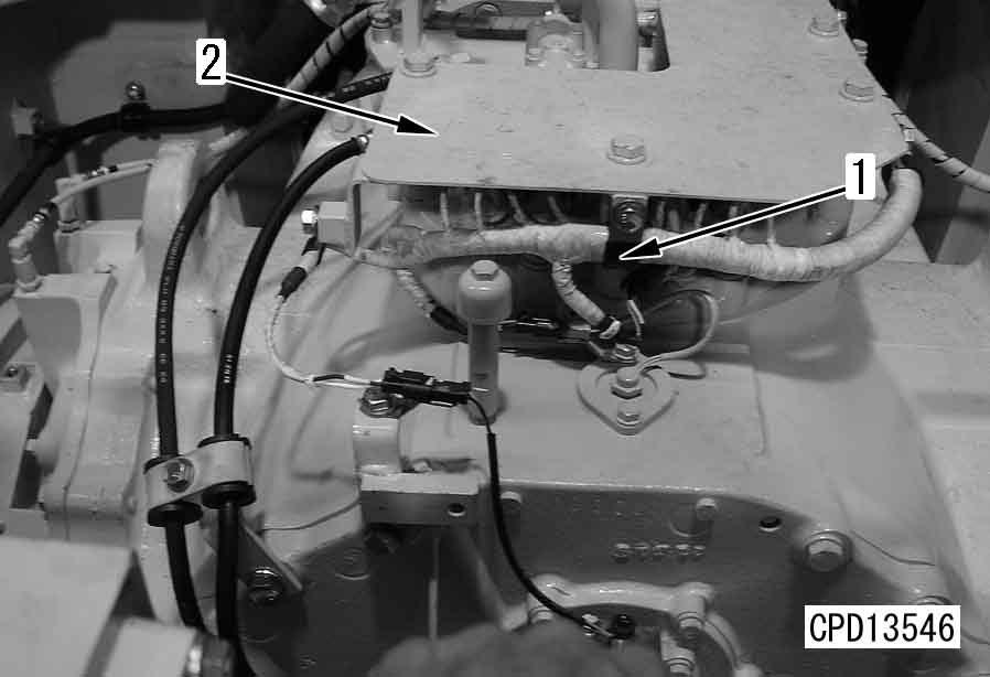
Installation q Carry out installation in the reverse order to removal.
Disassembly and assembly of steering control valve assembly
Disassembly of ECMV assembly
q Before removing the ECMV assembly from the steering assembly, clean around it so that dirt will not enter it and steering assembly.
q Keep the removed parts so that they will not be damaged.
1.Flow control valve
1)Remove bracket (25), switch assembly (17), and cover (28) from valve body (1).
2)Remove springs (18) and (19) and spring seat (20).
3)Remove sleeve (23), spring (22), and pin (21).
2.Pressure control valve
1)Remove solenoid (2) from valve body (1). a Mask the solenoid to prevent dirt from entering it.
2)Remove valve (3) and ball (4).
a Keep the ball so that it will not be lost.
3)Remove spool (7).
a When removing the spool, check that it moves smoothly.
4)Remove spring (13) and shims (14) and (15) from spool (7). Then, remove ring (12), sleeve (10), spring (9), and poppet (8).
a Check the quantity of shims (14) and (15).
Assembly of ECMV assembly
a If the pressure control valve was disassembled or any part of it was replaced, be sure to check the oil pressure.
a Clean the all parts and check them for dirt or damage. Coat their sliding surfaces with engine oil before installing.
1.Pressure control valve q Standard number of shims: 3 q Standard shim thickness: 1.5 mm (Thickness of 1 shim: 0.2 mm, 0.5 mm) a Check that the spool moves smoothly. a When reusing all of valve body (1), spring (13), spool (7), solenoid (2), valve (3), sleeve (10), and spring (9), install the standard number of the shims. a When replacing solenoid valve (2), check that spring (13) is installed securely.
1)Install poppet (8), spring (9), O-ring (11), sleeve (10), and ring (12) to spool (7).
2)Install shims (14) and (15) and spring (13) to spool (7), and then install the spool to body (1).
3)Fit the O-ring to valve (3), install the ball, fit the O-ring to the solenoid, and install them to body (1).
2.Flow control valve
1)Install sleeve (23), spring (22), and pin (21) to body (1).
2)Install springs (19) and (18) to spring seat (20) and put them in cover (28). Fit Orings (26) and (27) and install switch assembly (17) and bracket (25) with bolts (24).
3.Testing ECMV oil pressure
Check the ECMV oil pressure. For details, see Testing and adjusting, Testing ECMV oil pressure.
4.Adjusting ECMV oil pressure
As a result of testing, if the oil pressure is out of the standard range, adjust it with shims (14) and (15).
a If the shim is increased, the oil pressure is heightened. If the former is decreased, the latter is lowered.
a Install the shim securely and do not drop it in the valve.
a After adjusting the shim, test the oil pressure again.
Removal and installation of final drive assembly
Special tools
4.Remove cover (3), then using forcing screw, pull out drive shaft (4). [*1] a If the shaft will not come out, set a jack on the ground and push the shoe grouser up, then move the sprocket to the front or rear to a position where the shaft will come out, and remove the shaft. a Pull the shaft out to a position where it contacts the sprocket.
Removal
1.Remove track shoe assembly. For details, see "Expansion and installation of track shoe assembly".
2.Raise chassis with jack or ripper and set stand [1] under frame.
3.Remove covers (1) and (2).
5.Remove 3 bolts of final drive and install tool J1
6.Sling final drive assembly (5), then remove mounting bolts, and lift off.[*2]
4 Final drive assembly: 3,600 kg
Installation q Carry out installation in the reverse order to removal.
[*1] a If the shaft will not go in, set a jack on the ground and push the shoe grouser up, then move the sprocket to the front or rear to a position where the shaft will go in, and install the shaft.
[*2]
2 Final drive assembly mounting bolt: Thread tightener (LT-2)
3 Final drive assembly mounting bolt: 1,960 – 2,450 Nm (200 – 250 kgm) q Refilling with oil (final drive case) Add oil through the oil filler to the specified level.
5 Final drive case: 71 l (GO140)
Disassembly and assembly of final drive assembly
Special tools
Disassembly
1.Draining oil
Remove drain plug and drain oil from final drive case.
6 Final drive case: Approx. 71 l
2.Sprocket
1)Set final drive assembly to block (height: approx. 50 mm).
2)Remove sprocket (1).
3.Cover
Using eyebolts [1], remove cover (2).
4.Hub
1)Remove plate (3).
2)Using eyebolts [2], lift off hub (4).
5.Sprocket hub assembly
1)Remove holder (5). a Check the number and thickness of the shims, and keep in a safe place.
4)Remove bearing inner race (8) from sprocket hub assembly.
2)Using tool J2, disconnect sprocket hub assembly (6) and bearing (7) portion.
3)Using eyebolts [3], remove sprocket hub assembly (6).
5)Turn over sprocket hub assembly, then remove floating seal cover (9) and bearing outer races (10) and (11).
6)Remove floating seal (12) from floating seal cover. a Keep the floating seal in a safe place to protect it from damage.
6.Wear guard
Lift off wear guard (13).
7.Cover assembly
1)Using eyebolts, lift off cover assembly (14).
2)Disassemble cover assembly as follows.
1]Remove floating seal cover (15).
2]Remove floating seal (16) from floating seal cover.
a Keep the floating seal in a safe place to protect it from damage.
2)Disassemble carrier assembly as follows.
1]Set carrier assembly on block (height: approx. 100mm).
2]Remove holder (21).
3]Using tool J7, remove planetary gear shaft (22).
3]Remove spacer (17) and bearing inner race (18).
4]Remove planet gear (23), bearing inner races (24A) and (24B), and spacer (24C).
4]Remove plate, then remove ring gear (19).
1)Using eyebolts [5], remove carrier assembly (20).
5]Remove bearing outer race (24D).
9.Sun gear
1)Remove plate (25).
2)Remove holder (26).
3)Pull out sun gear shaft assembly (27).
2)Using tool J5, pull out hub assembly (29) and bearing inner race (30) from shaft assembly (31).
4)Remove holder (51) from sun gear shaft assembly, and pull out sun gear (52)
3)Disassemble hub assembly (29) as follows.
1]Remove gear (32) from hub (33).
2]Remove bearing outer races (34A) and (34B).
10.Hub, shaft assembly
1)Remove plate (28).
4)Using eyebolts [6], pull out shaft assembly (31) from case.
5)Disassemble shaft assembly as follows.
1]Remove collar (36).
2]Remove bearing inner race (37) and collar (38).
11.Cage assembly
1)Using eyebolts [7], remove cage assembly (39).
2)Remove shims (40).
a Check the number and thickness of the shims, and keep in a safe place.
13.Outer race, oil seals
1)Using puller [10], remove bearing outer race (48).
2)Remove oil seals (49) and (50) from cover.
3)Disassemble cage assembly as follows.
1]Using puller [8], remove bearing outer race (41).
2]Remove oil seals (42) and (43).
Assembly a Clean all parts, and check for dirt or damage. Coat the sliding surfaces of all parts with engine oil before installing.
1.Hub, shaft assembly
1)Assemble shaft assembly as follows.
1]Install collar (38).
2]Using push tool [17], press fit bearing inner race (37).
3]Install collar (36).
12.Gear assembly
1)Remove gear assembly (44).
2)Using puller [9], remove bearing inner races (45) and (46) from gear (47).
2)Using eyebolts [6], install shaft assembly (31) to case.
3)Assemble hub assembly as follows.
1]Using push tool, press fit bearing outer races (34A) and (34B) to hub (33).
5)Install plate (28).
2 Mounting bolt: Thread tightener (LT-2)
3 Mounting bolt: 490 – 608 Nm{50 – 62 kgm}
2]Set gear (32) to hub (33).
2 Mounting bolt: Thread tightener (LT-2)
3 Mounting bolt: 823 – 1,029 Nm {84 – 105 kgm}
4)Set shaft assembly (31) and hub assembly (29) in position, then using tool J6 , press fit bearing (30) portion.
2.Carrier assembly a Set so that the protruding part at the end face of the planet gear faces the outside of the machine.
1)Assemble carrier assembly as follows. a The planetary gear bearing forms a set, so align the mating marks on the inner race, outer race, and spacer when assembling.
1]Install ring and spacer to planet gear, then using push tool [18], press fit top and bottom bearing outer races (24D).
2]Assemble spacer (24C) and bearing inner races (24B) and (24A) to planet gear (23), then set to carrier.
3.Sun gear
1)Press fit sun gear (52) to sun gear shaft, and install holder (51).
2 Holder mounting bolt: Thread tightener (LT-2)
2)Assemble sun gear shaft assembly (27) to carrier (53), then install holder (26) and spacer (25).
2 Holder mounting bolt: Thread tightener (LT-2) a Align the shaft with the position of the bearing and spacer hole, and press fit gradually.
3]Using tool J7, press fit planetary gear shaft (22).
4]Install holder (21).
2 Mounting bolt: Thread tightener (LT-2)
3 Mounting bolt: 490 – 608 Nm {50 – 62 kgm} a After tightening the bolts, check that the gear rotates smoothly.
4.Carrier,
Using eyebolts [5], install carrier and sun gear assembly (20).
5.Cover assembly
1)Assemble cover assembly as follows.
1]Using push tools [11] and [12], install oil seals (50) and (49).
a Install the bottom oil seal with the part receiving the pressure at the bottom; install the top oil seal with the part receiving the pressure at the top.
2 Lip of oil seal: Grease (G2-LI)
2 Oil seal press-fitting surface: Gasket sealant (LG-5) a Coat the inside surface of the case thinly with gasket sealant and wipe off any sealant that is forced out. a Install so that the cut-out portion of the floating seal cover is facing the bottom as shown in the diagram below.
6]Using tool J4, press fit floating seal (16) to floating seal cover. a Remove all oil and grease from the O-ring and O-ring contact surface, and dry before installing. a After installing the floating seal, check that the angle of the seal is less than 1 mm.
2]Using push tool [13], press fit bearing outer race (48) to cover.
7]Install floating seal cover (15). a Fit a cork plug in the forcing tap.
3]Fit ring gear (19) and install plate. a Fit so that the notched part of the end face of the gear faces the inside of the machine.
4]Install spacer (54), then using tool J3, press fit bearing inner race (18).
5]Install spacer (17).
7.Sprocket hub assembly
1)Using tool J4, install floating seal (12) to floating seal cover.
a Remove all oil and grease from the O-ring and O-ring contact surface, and dry before installing.
a After installing the floating seal, check that the angle of the seal is less than 1 mm.
2)Using eyebolts, raise cover assembly (14) and install.
2 Case mating surface: Gasket sealant (Three Bond 1216) a Check that there are no dents, rust, oil, grease, or water on the mating surface of the case and cover.
a Coat the whole circumference of the mating surface of the case (one side) with gasket sealant without any break.
a Install the cover assembly within 20 minutes after coating with gasket sealant.
3 Mounting bolt: 1,715 – 1,911 Nm {175 – 195 kgm}
6.Wear guard
1)Raise wear guard (13) and install.
2)Install wear guard plate (13a).
3 Mounting bolt: 823 – 1,029 Nm {84 – 105 kgm}
2)Using push tool, press fit bearing outer races (11) and (10).
3)Install floating seal cover (9).
4)Set bearing (8) to sprocket hub assembly.
5)Using eyebolts [3], sling sprocket hub assembly (6) and set to cover. a Check that there is no dirt on the sliding surface of the floating seal, then coat thinly with engine oil.
6)Using tool J3, press fit bearing (7) portion. a Rotate the sprocket hub assembly when press fitting.
8.Hub
1)Using eyebolts [2], raise hub (4) and install.
2)Install plate (3).
2 Mounting bolt: Thread tightener (LT-2)
3 Mounting bolt: 245 – 309 Nm {25 – 31.5 kgm}
7)Install holder (5). a Tighten 6 mounting bolts temporarily at equal distances around the circumference, then adjust with shims so that clearance (X) between cover (14) and holder (5) is within the standard value.
Clearance (X): 0.1 – 0.3 mm
3 Mounting bolt (temporary tightening):
Approx. 74 Nm {7.5 kgm}
2 Mounting bolt: Thread tightener (LT-2)
3 Mounting bolt: 490 – 608 Nm {50 – 62 kgm}
9.Cover Using eyebolts [1], install cover (2).
10.Sprocket
Install sprocket (1).
3 Mounting bolt:
2,500 – 2,794 Nm {255 – 285 kgm}
12.Cage assembly a Install the bottom oil seal with the part receiving the pressure at the bottom; install the top oil seal with the part receiving the pressure at the top.
1)Assemble cage assembly as follows.
1]Using push tools [11] and [12], install oil seals (43) and (42).
2 Lip of oil seal: Grease (G2-LI)
2 Oil seal press-fitting surface: Gasket sealant (LG-5) a Coat the inside surface of the case thinly with gasket sealant and wipe off any sealant that is forced out.
11.Gear assembly
1)Using push tool [14], press fit bearing inner races (46) and (45) to gear.
2)Set tool J8 to cover (14), and install gear assembly (44). a Leave tool J8 in position until the cage is installed.
2)Using eyebolt [7], set cage assembly (39) to case, and remove tool J8
3)Tighten mounting bolts (C), (D), (E), and (F) of cage (A) uniformly to a tightening torque of 69 Nm {7 kgm}, then loosen bolts.
4)Tighten mounting bolts (C) and (D) of cage (A) uniformly to a tightening torque of 20 Nm {2 kgm}.
5)In this condition, use feeler gauge [16] to measure clearances (a) and (b) between cage (A) and cage (B).
6)Determine thickness (c) of shims to insert according to Table 1 on next page.
7)Assemble shim set on the previous stage, then tighten mounting bolts of cage (A) uniformly.
3 Mounting bolts: 319 – 608 Nm {32.5 – 62 kgm}
13.Refilling with oil
Tighten drain plug and add engine oil through the oil filler to the specified level.
5 Final drive case: Approx. 71 l (GO140)
D475A-5E0
D475ASD-5E0
Undercarriage and frame, Part 1 1
Removal and installation of track frame assembly 1
Removal
1.Remove track shoe assembly. For details, see "Expansion and installation of track shoe assembly".
2.Raise chassis with jack or ripper, then set support [1] under frame to keep rear of chassis off ground.
3.Set hydraulic jack [2] to center of equalizer bar, and raise front of chassis.
4.Sling track frame assembly.
7.Using eyebolts [3], pull out pin (3).[*1] a It is difficult to remove the pin if the centers of the equalizer bar hole and track frame hole are not aligned, so adjust the height of the track frame before removing.
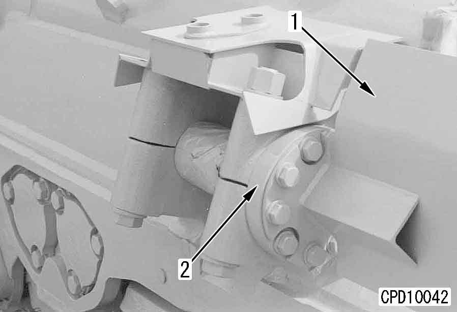
8.Remove mounting bolts, and disconnect cover (4) from track frame.
5.Remove cover (1).
6.Remove cover (2).
9.Remove cover (5). a With the right track frame, disconnect 4 blade tilt cylinder hoses from the cover.
10.Remove seal (6) together with washer (7).[*2]
11.Remove washer (8), then remove spacer (9).
12.Lift off track frame assembly (10).[*3] a Oil will flow out from the pivot case, so catch it in an oil container.
6 Pivot case: 26 l
4 Track frame assembly: 11,180 kg
Installation q Carry out installation in the reverse order to removal.
[*1]
2 Inside surface of bushing: Grease (G2-LI) a Before installing the pin, adjust the height of the track frame and align the center of the equalizer bar hole and track frame hole. a Set the pin with the grease hole facing the outside of the machine.
[*2] a After removing the grease from the pressfitting surface of the seal, coat with gasket sealant (LG-6). a Be careful not to install with the seal displaced in the direction of twisting.
[*3] a Be careful not to install the track frame with seal (11) displaced in the direction of twisting.
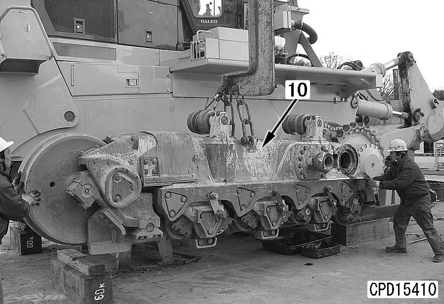
D475A, D475ASD-5E0 q Refilling with oil (pivot case)
Add oil through oil filler to the specified level.
5 Pivot case: 26 l (SAE30)
Disassembly and assembly of idler assembly
Special tools
Disassembly
1.Remove oil filler plug and drain oil.
6 Idler: 2.0 – 2.2 l (GO140) a Keep the floating seal in a safe place to protect it from damage. a Keep the floating seal in a safe place to protect it from damage. a Check that the plate can be turned smoothly with the hand.
2.Set idler assembly (1) on block [1].
3.Remove mounting bolts, then using forcing screws [2], remove seal guide (2) together with retainer (3) and plate (4).
6.Using puller [4], remove seal guide (6) and retainer (7) and plate (8).
4.Turn over idler assembly.
5.Remove mounting bolts, then using eyebolts [3], remove shaft (5) together with retainer.
7.Remove seal guides (2) and (6) from retainers (3) and (7).
8.Remove floating seal (9) from seal guides (2) and (6).
9.Remove floating seal (10) from seal guides (3) and (7).
10.Remove bushings (11) from idler (12).
2.Using tool L2 , install floating seal (10) to retainers (3) and (7).
3.Fit O-ring and install retainer (3) and plate (4) to idler.
Assembly a Clean all parts, and check for dirt or damage. a First, center the bushing with a plastic hammer, then press fit with a puller. a Press fit so that press-fitting dimension (a) from the end face of the idler to the top surface of the bushing is the dimension given below. q Press-fitting dimension (a): 17 ± 0.5 mm
1.Set bushing (11) and tool L1 to idler (12), and press fit bushing (11).
4.Using eyebolts [3], set idler (12) to shaft (5). a Set block (height: approx. 200 mm) under the idler.
5.Turn over idler assembly. a Tie with wire to prevent the shaft from falling out.
6.Fit O-ring and install retainer (7) and plate (8) to idler.
D475A, D475ASD-5E0
7.Using tool L2, install floating seal (9) to seal guides (2) and (6).
9.Using tool L4, fill with oil to specified level, then tighten oil filler plug.
5 Idler: 1.4 – 1.5 l (GO140)
3 Oil filler plug: 156.8 – 254.8 Nm {16 – 26 kgm} a Seal guide press-fitting force: 83.3 – 137.2 kN {8.5 – 14 ton} a Press fit the seal guide so that press-fitting dimension (a) from the end face of the shaft to the top surface of the seal guide is the dimension given below. q Press-fitting dimension (a): 124.5 ± 0.2 mm a Turn over the idler assembly and repeat the same procedure to press fit the seal guide (6) on the opposite side.
8.Set seal guide (2) to shaft, then using tools L1 and L3, press fit seal guide (2).
Removal and installation of recoil spring assembly
Special tools
Removal k To prevent danger, never stand in front of the idler yoke assembly.
1.Remove track shoe assembly. For details, see "Expansion and installation of track shoe assembly".
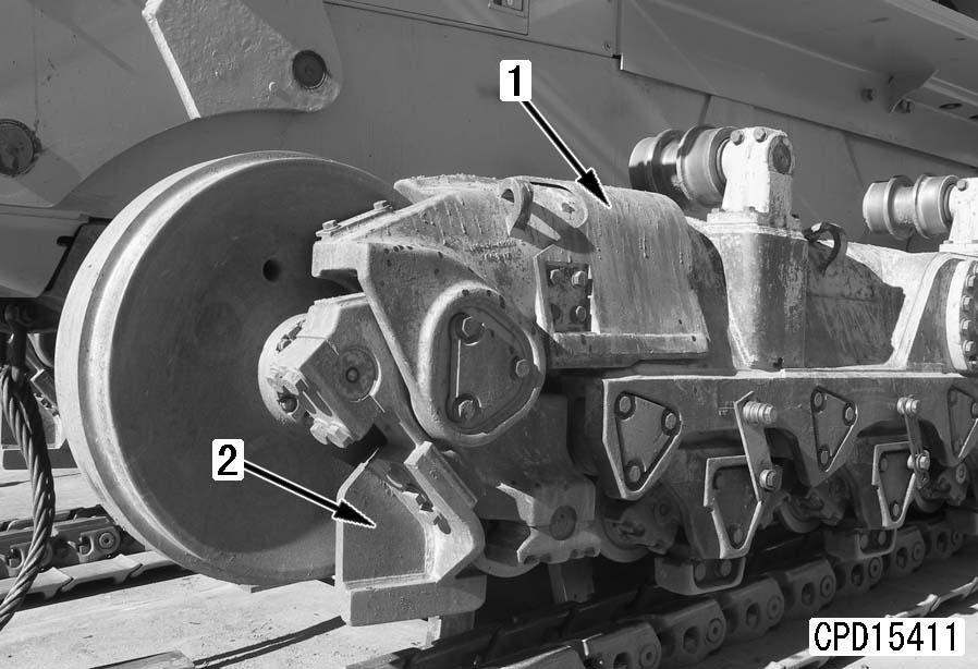
2.Drain oil from recoil cylinder chamber using oil pump.
6 Recoil cylinder chamber: Approx. 75 l
3.Using eyebolt [1], remove cover (1). 4 Cover: 70 kg
4.Remove cover (2).
5.Lift off trunnion (3). 4 Trunnion: 140 kg
6.Remove covers (4). a Remove both the inside and outside covers.
7.Using tool M1, remove pins (5).[*1] a Remove both the inside and outside pins.
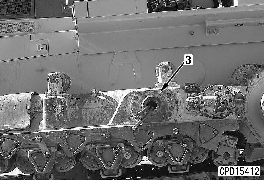
8.Lift off idler and recoil spring assembly (6).[*2] a Using a lever block, keep the assembly horizontal, and be careful not to damage the oil seal at the track frame end.
4 Idler, recoil spring assembly: 3,500 kg
2)Loosen idler yoke mounting bolts (9) gradually in turn on diagonally opposite sides. [*4]
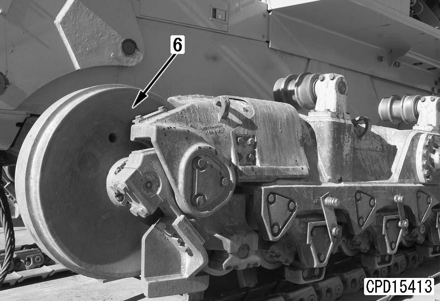
9.Disconnect recoil cylinder assembly (7) from idler yoke assembly (8) as follows.[*3] a When doing this, check that there is no damage to the weld of recoil cylinder assembly (7). a Wrap cloth around the chrome plated bushing to protect it. k To prevent danger, never stand in front of the idler yoke assembly or behind the recoil cylinder assembly. k The recoil spring inside the recoil cylinder is applying a pushing force of approx. 788 kN {approx. 81 tons} on the idler yoke, so be careful not to loosen the mounting bolts suddenly. Loosen the mounting bolts gradually until clearance (a) between the flange of the recoil cylinder and idler yoke is 8 – 12 mm. a If the torque increases (the installed load of the recoil spring is applied) during the loosening operation, stop the loosening operation and disassemble as follows. k If the torque does not drop during Steps 2) and 3) described above, and the torque when the bolts are loosened remains large, there is probably damage to recoil spring set bolt (10), or nut (11) at the tip of the shaft has fallen off, so there is danger that the idler yoke assembly may fly off to the front. For this reason, disassemble as follows. k When disconnecting the idler yoke assembly and recoil cylinder assembly, do not stand in front of the idler yoke assembly or behind the recoil cylinder assembly until safety has been confirmed and the recoil spring assembly has been removed. q Bolt [1] (x 6): 791-730-1120 q Nut [2] (x 6): 01580-13326 q Washer [3] (x 6): 01643-33380 (use again) a Check that dimension L is less than 450 mm. a Screw in bolts [1] until they contact the bottom of the yoke (Y) thread. a Be careful not to let the load bear on only one bolt. a When clearance (b) is approx. 280 mm, the spring is fully extended.
1)Put idler yoke assembly (8) in contact with ground, then raise recoil cylinder assembly (7).
3)When the bolts are loosened, the torque will suddenly drop. Check that the installed load of the recoil spring is not applying any pushing force on the mounting bolts, then remove all bolts.
1]Prepare the following parts.
2]Remove 6 bolts marked , then install bolts [1], nuts [2], and washers [3].
3]Remove remaining 12 bolts (those not marked ).
4]Hold bolts [1] with a wrench to prevent them from turning, and loosen 2 nuts [2] simultaneously on diagonally opposite sides.
5]When recoil spring is fully extended and torque has completely dropped in loosening direction of nut [2], remove bolt [1].
10.Remove ring (12).
11.Pump in grease through lubricator (13), and remove cylinder (14) and piston assembly (15).
[*5]
14.Remove holder (20) from recoil spring assembly.
12.Disassemble piston assembly (15) as follows.
1)Remove wear ring (16) from piston.
2)Remove snap ring (17), then remove packing (18).
Installation q Carry out installation in the reverse order to removal.
[*1] a Before installing the pin, align the center of the hole in the track frame and the dowel pin at the recoil cylinder end with a bar.
[*2] a Using a lever block, keep horizontal and be careful not to damage the oil seal at the track frame end when installing. a Adjust the clearance. For details, see Testing and adjusting, Adjusting clearance of idler.
13.Remove recoil spring assembly (19).
4 Recoil spring assembly: 780 kg
[*3] a If the recoil spring set bolt is broken or the nut at the tip of the shaft has fallen off, see Assembly of recoil spring assembly when assembling.
[*4]
2 Idler yoke assembly mounting bolt: Thread tightener (LT-2)
3 Idler yoke assembly mounting bolt:
2,205 – 2,695 Nm {225 – 275 kgm}
[*5] a To prevent air from accumulating inside the cylinder, fill with grease as follows.
1]Fill the inside of the cylinder with approx. 2.0 l of grease.
2]Set with the cylinder drain hole facing up, then loosen the lubricator.
3]Push the piston until it contacts the stopper. This will push out the air and any extra grease.
Disassembly and assembly of recoil spring assembly
Special tools
791-685-8502Compressor
791-635-3160Extension
790-201-2790Spacer
790-101-1300 Cylinder (980 kN {100 ton})
790-101-1102Pump
Disassembly
1.Remove recoil spring assembly (1) with tool M2 k The spring is under high installed load, so be careful to set it correctly. a Installed load of spring: Approx. 788 kN {approx. 81 ton}
2.Apply hydraulic pressure slowly to compress spring, then remove lock plate (2) and remove nut (3).
3.Release hydraulic pressure gradually and relieve tension of spring.
4.Remove rear pilot (5), spacer (6), bolt (7), and front pilot (8) from spring (4).
Assembly
1.Assemble front pilot (8), bolt (7), spacer (6), and rear pilot (5) to spring (4), then set in tool M2 k The spring is under high installed load, so be careful to set all parts correctly. a Installed length (a) of spring: 1,461 mm a Installed load of spring: Approx. 788 kN {approx. 81 ton}
2.Apply hydraulic pressure slowly to compress spring, and set so that installed length of spring is specified value.
3.Fit nut (3), then install lock plate (2). a When securing the recoil spring mounting nut, make a clearance (b) of 0 – 1 mm between lock plate (2) and nut (3), then bring lock plate (2) and bolt (7) into tight contact, and secure in position.
2 Lock plate mounting bolt: Thread tightener (LT-2)
4.Gradually release hydraulic pressure to completely release tension of spring, then remove recoil spring assembly (1) from tool M2
Removal and installation of track roller assembly
Special tools
5.Remove the mounting bolts and place track roller assembly (2) on steel plate [1].[*2]
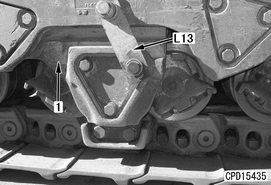
6.Operate the blade and ripper to lift the machine body until track roller assembly (2) separates from the bogie.
Removal
1.Loosen the track shoe. For details, see "Expansion and installation of track shoe assembly".
2.Install tool L13 and secure bogie assembly (1). [*1]
3.Operate the blade and ripper to lift the machine body until track roller assembly (2) separates from the track shoe.
4.Place steel plate [1] on the track shoe and operate the blade and ripper to lower the machine body until the track roller assembly comes in contact with the steel plate. a Operate the blade and ripper slowly, running the engine at the low idling speed.
7.Pull track roller assembly (2) out of the machine body from the top of the steel plate with a bar, etc.[*3] 4 Track roller assembly: 240 kg