1 minute read
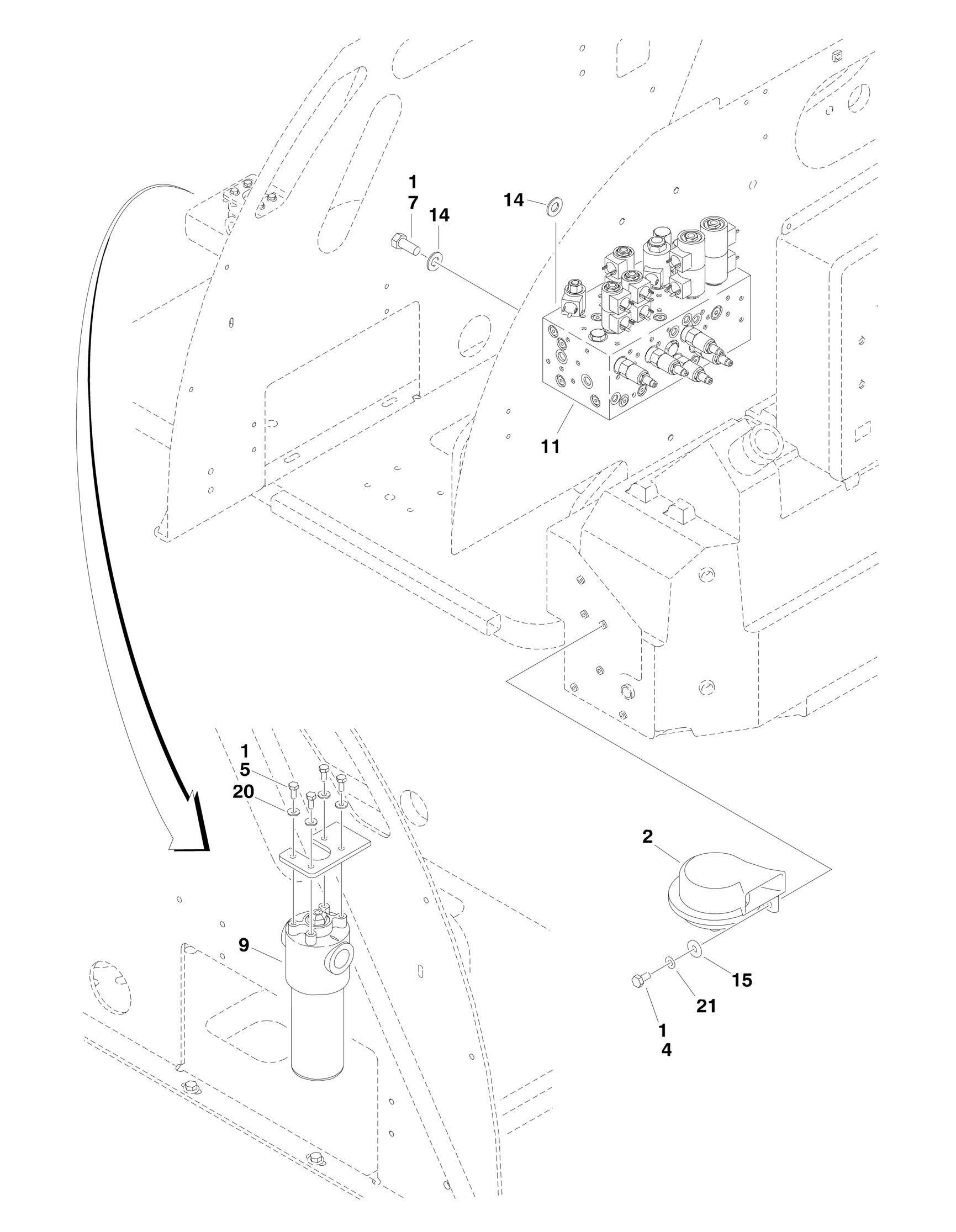
FIGURE 2-1. CONTROL VALVE INSTALLATION


FIGURE 2-1. CONTROL VALVE INSTALLATION
FIGURE 2-1. CONTROL VALVE INSTALLATION
ITEM PART NUMBER QTY
DESCRIPTION
Ref VALVES INSTALLATIONS 0274615 Ref Valves Installations 450A Series II 0274616 Ref Valves Installations 450AJ Series II 1 0100011 AR Compound, Locking 2 0140001 1 Horn 4 0641404 1 Bolt 1/4in-20NC x 1/2in 5 0651405 4 Bolt 1/4in-24NF x 5/8in 7 0641607 4 Bolt 3/8in-16NC x 7/8in 9 2120209 1 Pressure Filter Assembly 9 2120210 Element, Filter 9 7020020 1 Indicator 9 70000934 1 O-Ring, Filter Bowl 11 4641176 1 Main Control Valve Assembly (See MAIN CONTROL VALVE ASSEMBLY for Breakdown) 14 4711600 10 Flatwasher 3/8in Thin 15 4751400 1 Flatwasher 1/4in Regular 20 4711400 4 Flatwasher 1/4in Thin 21 4791400 1 Starwasher 1/4in
REV
A A


