1 minute read
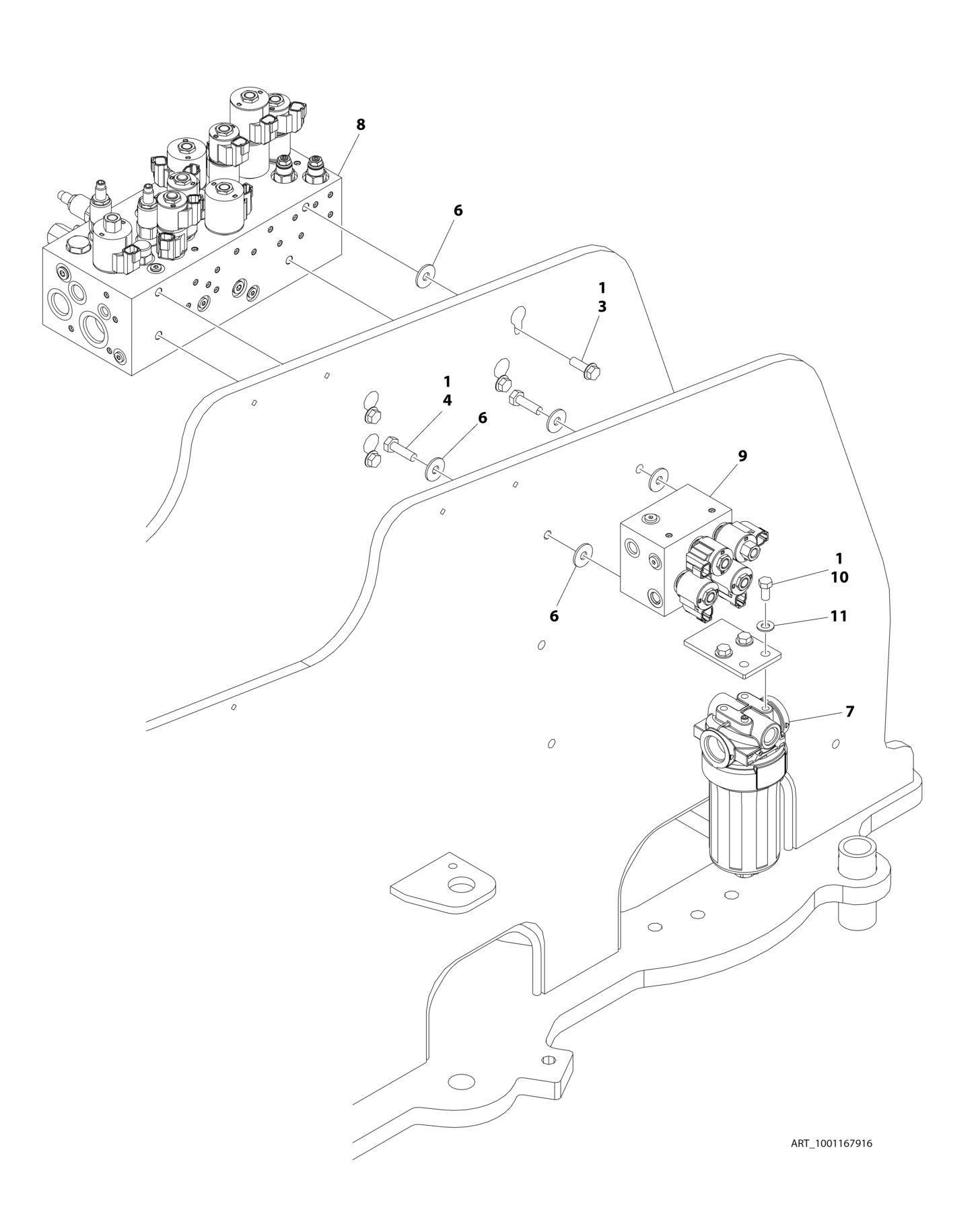
FIGURE 2-1. CONTROL VALVES INSTALLATION (400S HC3


ITEM PART NUMBER QTY
DESCRIPTION
1001167916 Ref CONTROL VALVES INSTALLATION 1 0100011 AR Compound, Locking 3 5251014 4 Bolt M10 x 30 4 0761015 2 Bolt M10 x 35 6 4812002 8 Washer M10 7 1001208874 1 Filter, Charge Pump 7 70010383 1 Element, Filter (Includes O-Ring) 8 1001162531 1 Main Valve Assembly (See Separate Breakdown in this Section) 9 1001162538 1 Axle Valve Assembly (See Separate Breakdown in this Section) 10 0761010 3 Bolt M10 x 20 11 4812000 3 Washer M10
REV
F