JLG 18RS 18RSJ Parts Manual (3121285)-PDF Download

Page 17

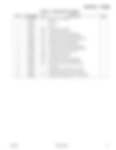
SECTION 1 - FRAME FIGURE 1-3. DRIVE MOTOR ASSEMBLY ITEM 1 2 3 4 5 6 7 8 9 10 11 12 13 14 15 16 17 18 19 20 21 27 50

3121285

PART NUMBER 1001132500 70004126 70004075 70004076 See Note See Note 70004077 70004078 70004079 70004080 70004081 70004082 70004083 70004084 See Note See Note 70004085 70004086 70004087 70004088 See Note See Note 70004089 70004090

QTY Ref 1 1 1 NSS NSS NLA NLA NLA NLA NLA NLA NLA NLA NSS NSS NLA NLA NLA 4 1 4 NLA 1

DESCRIPTION DRIVE MOTOR ASSEMBLY O-Ring Seal, Shaft Plug O-Ring (Note: Use Item 50) O-Ring (Note: Use Item 50) Shaft (Note: Purchase Complete Motor) Gear Set (Note: Purchase Complete Motor) Coupling, Drive (Note: Purchase Complete Motor) Plate (Note: Purchase Complete Motor) Ball (Note: Purchase Complete Motor) Plate, Valve (Note: Purchase Complete Motor) Plate, Balance (Note: Purchase Complete Motor) Pin (Note: Purchase Complete Motor) O-Ring (Note: Use Item 50) O-Ring (Note: Use Item 50) Washer (Note: Purchase Complete Motor) Spacer (Note: Purchase Complete Motor) Cover, End (Note: Purchase Complete Motor) Screw M10 Nameplate (Note: Not Available for Purchase) Rivet (Note: Not Available - Purchase Locally) Flange, Mounting (Note: Purchase Complete Motor) Seal Kit - Motor (Includes Items 1, 2, 4, 5, 14 & 15)

18RS_18RSJ

REV E

17


Turn static files into dynamic content formats.

Create a flipbook

Articles inside

FIGURE 10-1. RECOMMENDED SERVICE PARTS STOCK

1min
page 362

FIGURE 11-1. SPECIAL OPTIONS

2min
pages 364-366

FIGURE 8-34. VALVE HARNESS - 18RS

1min
pages 328-329

FIGURE 8-33. TURNTABLE HARNESS

2min
pages 324-327

FIGURE 8-29. PLATFORM BOX HARNESS - 18RS (Prior to SN B300001836

1min
pages 316-317

FIGURE 8-31. PLATFORM BOX HARNESS - 18RSJ

1min
pages 320-321

FIGURE 8-27. JIB HARNESS

1min
pages 312-313

FIGURE 8-26. GROUND CONTROL PANEL HARNESS - 18RSJ

1min
pages 310-311

FIGURE 8-30. PLATFORM BOX HARNESS - 18RS (SN B300001836 to Present

1min
pages 318-319

FIGURE 8-25. GROUND CONTROL PANEL HARNESS - 18RS

1min
pages 308-309

FIGURE 8-23. EMR2 POWER HARNESS

1min
pages 304-305

FIGURE 8-21. BOOM HARNESS - TOWER BOOM

1min
pages 300-301

FIGURE 8-18. BOOM CABLES INSTALLATION - 18RSJ WITH SKYPOWER

1min
pages 294-295

FIGURE 8-20. BOOM HARNESS - MAIN BOOM - 18RSJ

1min
pages 298-299

FIGURE 8-19. BOOM HARNESS - MAIN BOOM - 18RS

1min
pages 296-297

FIGURE 8-17. BOOM CABLES INSTALLATION - 18RSJ WITHOUT SKYPOWER

1min
pages 292-293

FIGURE 8-16. BOOM CABLES INSTALLATION - 18RS WITH SKYPOWER

1min
pages 290-291

FIGURE 8-15. BOOM CABLES INSTALLATION - 18RS WITHOUT SKYPOWER

1min
pages 288-289

FIGURE 8-9. AC TO PLATFORM CABLE - MAIN BOOM (18RSJ WITH SKYPOWER) (Prior to SN B300001836

1min
pages 276-277

FIGURE 8-4. AC AT PLATFORM RECEPTACLE COMPONENTS - DEALER/CUSTOMER SUPPLIED

1min
pages 266-267

FIGURE 8-2. AC AT PLATFORM RECEPTACLE COMPONENTS - 110V GFI (ANSI EXPORT SPECS

1min
pages 262-263

FIGURE 8-7. AC TO PLATFORM CABLE - MAIN BOOM (18RS WITH SKYPOWER) (Prior to SN B300001836

1min
pages 272-273

FIGURE 7-11. HYDRAULIC DIAGRAM LIST

1min
page 258

FIGURE 7-9. HYDRAULIC FLUSHING LOOP INSTALLATION - 18RS

1min
pages 254-255

FIGURE 7-10. HYDRAULIC FLUSHING LOOP INSTALLATION - 18RSJ

1min
pages 256-257

FIGURE 6-12. TELESCOPE CYLINDER ASSEMBLY - 18RSJ

1min
pages 216-217

FIGURE 8-3. AC AT PLATFORM RECEPTACLE COMPONENTS - 220V (ANSI EXPORT SPECS

1min
pages 264-265

FIGURE 6-7. MASTER CYLINDER ASSEMBLY - 18RS

1min
pages 206-207

FIGURE 6-9. STEER CYLINDER ASSEMBLY

1min
pages 210-211

FIGURE 6-5. LIFT CYLINDER ASSEMBLY - MAIN BOOM - 18RS

1min
pages 202-203

FIGURE 6-6. LIFT CYLINDER ASSEMBLY - MAIN BOOM - 18RSJ

1min
pages 204-205

FIGURE 6-3. LIFT CYLINDER ASSEMBLY - JIB - 18RSJ (Prior to SN B300003130

1min
pages 198-199

FIGURE 6-8. MASTER CYLINDER ASSEMBLY - 18RSJ

1min
pages 208-209

FIGURE 6-4. LIFT CYLINDER ASSEMBLY - JIB - 18RSJ (SN B300003130 to Present

1min
pages 200-201

FIGURE 6-2. LEVEL (PLATFORM SLAVE) CYLINDER ASSEMBLY - 18RSJ

1min
pages 196-197

FIGURE 6-1. LEVEL (PLATFORM SLAVE) CYLINDER ASSEMBLY - 18RS

1min
pages 194-195

FIGURE 5-14. CONTROLLER ASSEMBLY (LIFT AND SWING

1min
pages 182-183

FIGURE 5-16. CONTROLLER ASSEMBLY (DRIVE AND STEER

1min
pages 188-189

FIGURE 5-15. CONTROLLER ASSEMBLY (LIFT AND SWING

2min
pages 184-187

FIGURE 5-13. CONSOLE BOX ASSEMBLY (SN B300001836 to Present

1min
pages 180-181

FIGURE 5-10. CONSOLE BOX ASSEMBLY (Prior to SN B300001540

1min
pages 174-175

FIGURE 5-11. CONSOLE BOX ASSEMBLY (SN B300001540 to Present

1min
pages 176-177

FIGURE 5-9. PLATFORM ASSEMBLY – 3FT X 6FT (91.5CM X 1.83M) WITH TRI-ENTRY (3 DROP BARS

1min
pages 172-173

FIGURE 5-5. PLATFORM CONSOLE ASSEMBLY - 18RS (SN B300001441 to Present

2min
pages 160-163

FIGURE 5-8. PLATFORM ASSEMBLY - 3FT X 6FT (91.5CM X 1.83M) WITH TRI-ENTRY (1 GATE / 2 DROP BARS

1min
pages 170-171

FIGURE 5-7. PLATFORM ASSEMBLY - 30IN X 3FT (76CM X .91M) - DROP BAR ENTRY

1min
pages 168-169

FIGURE 5-6. PLATFORM CONSOLE ASSEMBLY - 18RSJ

2min
pages 164-167

FIGURE 5-4. PLATFORM CONSOLE ASSEMBLY - 18RS (Prior to SN B300001441

2min
pages 156-159

FIGURE 5-1. PLATFORM ASSEMBLY

1min
pages 150-151

FIGURE 4-13. PLATFORM SUPPORT INSTALLATION - WITH LSS

1min
pages 144-145

FIGURE 4-12. PLATFORM SUPPORT INSTALLATION - WITHOUT LSS - 18RSJ

1min
pages 142-143

FIGURE 4-8. PROXIMITY SWITCH INSTALLATION - 18RSJ

1min
pages 134-135

FIGURE 4-7. PROXIMITY SWITCH INSTALLATION - 18RS

1min
pages 132-133

FIGURE 3-6. PISTON PUMP ASSEMBLY

3min
pages 104-107

FIGURE 4-6. POWER TRACK ASSEMBLY

1min
pages 130-131

FIGURE 4-11. PLATFORM SUPPORT INSTALLATION - WITHOUT LSS - 18RS

1min
pages 140-141

FIGURE 4-10. PLATFORM ROTATOR ASSEMBLY - 18RSJ

1min
pages 138-139

FIGURE 4-9. PLATFORM ROTATOR ASSEMBLY - 18RS

1min
pages 136-137

FIGURE 3-5. PUMP COUPLING INSTALLATION

1min
pages 102-103

FIGURE 3-2. ENGINE AND PUMP ASSEMBLY

1min
pages 92-93

FIGURE 3-1. DEUTZ ENGINE INSTALLATION

1min
pages 90-91

FIGURE 2-21. BEACON LIGHT INSTALLATION (OPTIONAL

1min
pages 78-79

FIGURE 2-20. LIMIT SWITCH INSTALLATION

1min
pages 76-77

FIGURE 2-19. ELECTRICAL PANEL ASSEMBLY

1min
pages 74-75

FIGURE 2-18. GROUND CONTROL DOOR INSTALLATION (OPTIONAL

1min
pages 72-73

FIGURE 2-17. KEY SWITCH ASSEMBLY

1min
pages 70-71

FIGURE 2-23. CENTER HOOD ASSEMBLY (ENGINE SIDE

1min
pages 84-85

FIGURE 2-16. GROUND CONTROL PANEL ASSEMBLY - 18RSJ

1min
pages 68-69

FIGURE 2-15. GROUND CONTROL PANEL ASSEMBLY - 18RS

1min
pages 66-67

FIGURE 2-14. ELECTRICAL INSTALLATION - 18RSJ

1min
pages 64-65

FIGURE 2-13. ELECTRICAL INSTALLATION - 18RS

1min
pages 62-63

FIGURE 2-6. SWING MOTOR ASSEMBLY

1min
pages 48-49

FIGURE 2-12. WATER SEPARATOR FILTER ASSEMBLY (OPTIONAL

1min
pages 60-61

FIGURE 2-9. HYDRAULIC TANK ASSEMBLY

1min
pages 54-55

FIGURE 2-11. FUEL FILTER INSTALLATION (OPTIONAL

1min
pages 58-59

FIGURE 2-5. TURNTABLE BEARING AND SWING DRIVE INSTALLATION

1min
pages 46-47

FIGURE 2-4. MAIN CONTROL VALVE ASSEMBLY - 18RSJ

2min
pages 42-45

FIGURE 2-3. MAIN CONTROL VALVE ASSEMBLY - 18RS

2min
pages 38-41

FIGURE 1-8. FLOW DIVIDER VALVE ASSEMBLY

1min
pages 28-29

See Note 1 Nameplate (Note: Not Available for Purchase

1min
page 20

70004089 NLA Flange, Mounting (Note: Purchase Complete Motor

1min
page 27

FIGURE 1-5. TIRE AND WHEEL INSTALLATION

1min
pages 22-23

FIGURE 1-6. DRIVE VALVES INSTALLATION - 18RS

1min
pages 24-25

70004086 NLA Spacer (Note: Purchase Complete Motor

1min
page 17

70004088 4 Screw M10

1min
page 19

70004084 NLA Pin (Note: Purchase Complete Motor

1min
page 13
Issuu converts static files into: digital portfolios, online yearbooks, online catalogs, digital photo albums and more. Sign up and create your flipbook.