COMPONENT REPAIR AND TESTING GENERAL 1. To check for wire connections to the frame, disconnect the battery so that the connector is completely free and use an ohmmeter to check the circuits. Check for 50,000 ohms or more between each terminal of the part of the battery connector on the lift truck and a clean connection on the frame. Make sure there are no electrical connections to the frame of the lift truck. Wires or terminals without insulation can cause these connections. Isolators for circuit boards that are missing, broken or not installed correctly can also cause these connections.
NOTE: The lift pump motor contactor, the “HMR” (hour meter relay) and the “HR” (horn relay) are located in the drive unit compartment.
1 13 2 3 4 12
2. Check for voltage between each terminal of the connector on the battery and a clean metal connection on the frame of the lift truck. It is normal to measure some voltage between the battery and the frame even if the resistance checks are correct. If a voltage is measured, use an ammeter to determine if the level is acceptable. Current in excess of 100 milliamperes can cause a problem.
11 5 6
There can be a voltage on the frame if the battery is dirty or if the battery has a defect. Clean the battery and battery compartment as necessary. There can also be a voltage on the frame if there is carbon dust in the motors. Use dry compressed air to remove the carbon dust from all motors.
7
10
9 8
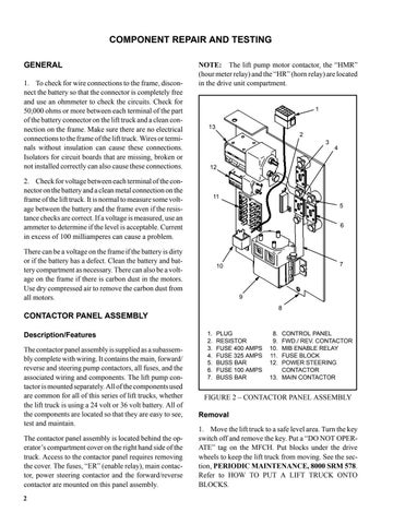
CONTACTOR PANEL ASSEMBLY Description/Features The contactor panel assembly is supplied as a subassembly complete with wiring. It contains the main, forward/ reverse and steering pump contactors, all fuses, and the associated wiring and components. The lift pump contactor is mounted separately. All of the components used are common for all of this series of lift trucks, whether the lift truck is using a 24 volt or 36 volt battery. All of the components are located so that they are easy to see, test and maintain. The contactor panel assembly is located behind the operator’s compartment cover on the right hand side of the truck. Access to the contactor panel requires removing the cover. The fuses, “ER” (enable relay), main contactor, power steering contactor and the forward/reverse contactor are mounted on this panel assembly. 2
1. 2. 3. 4. 5. 6. 7.
PLUG RESISTOR FUSE 400 AMPS FUSE 325 AMPS BUSS BAR FUSE 100 AMPS BUSS BAR
8. 9. 10. 11. 12.
CONTROL PANEL FWD./ REV. CONTACTOR MIB ENABLE RELAY FUSE BLOCK POWER STEERING CONTACTOR 13. MAIN CONTACTOR
FIGURE 2 – CONTACTOR PANEL ASSEMBLY Removal 1. Move the lift truck to a safe level area. Turn the key switch off and remove the key. Put a “DO NOT OPERATE” tag on the MFCH. Put blocks under the drive wheels to keep the lift truck from moving. See the section, PERIODIC MAINTENANCE, 8000 SRM 578. Refer to HOW TO PUT A LIFT TRUCK ONTO BLOCKS.
