11 minute read
Engine Diagnostic Chart (end)

from Gehl V4200 V420 (EU) V420 X-Series Skid-Steer Loaders Operator’s Manual 50950233 - PDF DOWNLOAD

5240819 Plausibility Error
5241089 Timeout Error
5241099 Timeout Error
NOx sensor upstream SCR-CAT, lambda value below lower physical threshold
Missing CAN message of EGR throttle valve; Timeout Error of CAN-Transmit-Frame ComEGRTVActr, Missing CAN Bus message
Missing message of EGR throttle valve; Timeout error of CAN-Receive-Frame
ComRxEGRTVActr, Missing CAN Bus message
5241332 Electrial Error State of digital input standstill release switch
5241340 Threshold Error
5241350 Threshold Error
52413514 Threshold Error
5241477 SCR System Error
52414713 Plausibility Error
5241522 Timeout Error (CAN)
5241532 Timeout Error (CAN)
5241750 Threshold Error
5241787 Out-of-Range Error (CAN)
52419014 DEF Error
52419114
5241938 Timeout Error
5241948 Timeout Error
52419514
DPF ash load exceeds the shutoff threshold
DPF ash load exceeds the warning threshold; DPF soot load exceeds the shutoff threshold
DPF soot load exceeds the service request threshold
SCR system reverting valve blocked
SCR system pressure build-up not possible
Set together with DFC_SCRCoBldUpLoPres.
DFC_SCRCoBldUpLoPresRst is only used for inducement purposes. It ensures that legal inducement is working correctly
Urea quality sensor; Timeout CAN message
Urea tank level and urea tank temperature via CAN bus, timeout of CAN message
SCR-CAT Nox emissions above maximum threshold
SCR system DEF pressure out-of-range
Inducement level 1 active; Not enough urea in tank, low urea quality, hardware tampering failure is detected, or hardware failure is detected
Inducement level 2 active; Low DEF tank level, a low DEF quality is detected, hardware tampering(system components are pinched off) or hardware failures as shortcut to battery, shortcut to ground etc. are detected
Standstill regeneration mode time exceeds longlimit threshold; machine too long or too often in standstill mode
Standstill regeneration mode time exceeds short-limit; Machine too long or too often within a short time in standstill mode
Standstill request due to crystalisation ignored too long
General inducement error. Refer to official Deutz engine error code documentation for more information
Hydraulic System
Refer to the Maintenance Interval Chart (page115) for service intervals.
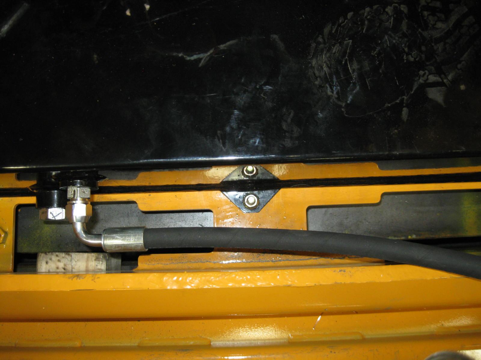
Checking Hydraulic Oil Level
Inside the engine compartment, the machine has a hydraulic tank dipstick left of the coolant tank. To check the level, run the machine to allow the hydraulic system to reach its operating temperature, then let the engine IDLE and remove the dipstick. Clean the dipstick and replace in its holder. Remove the dipstick again and check the fluid level, (Fig.17).
Add hydraulic oil as required in the hydraulic oil fill tube. The fill tube is located under a cover at the left side of the engine compartment. Refer to the Lubri cation chart (page76). Replace the fill cap.

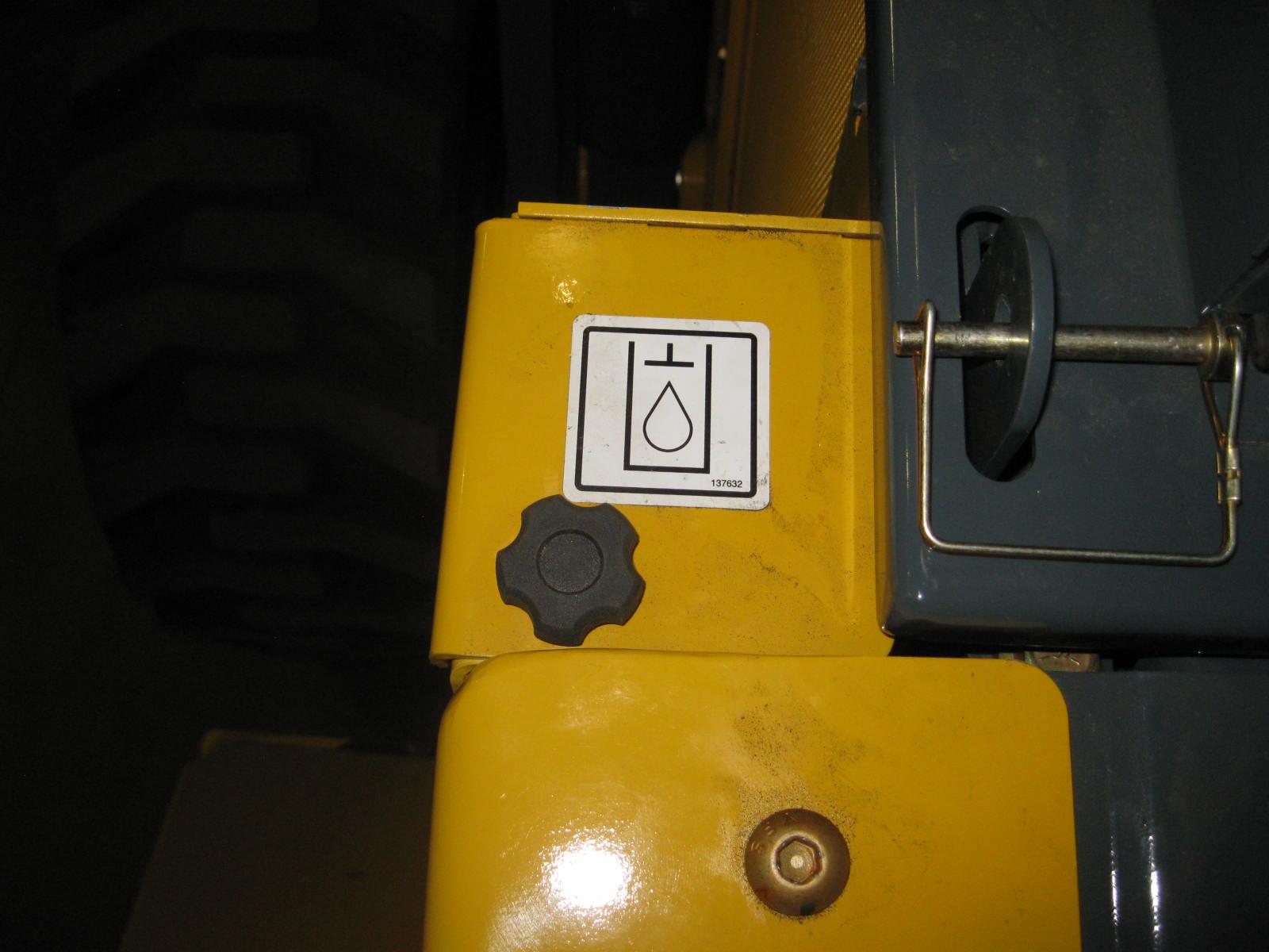
Changing Hydraulic Oil Filter
The hydraulic oil filter element is located underneath a flat cover plate on top of the reservoir tank. To change the hydraulic filter element:
1.Park the machine on a level surface and raise the lift arm, refer to the Lift Arm Support Device Engagement Procedure (page28). Shut off the engine and remove the key.
2.Tilt back the ROPS/FOPS, refer to the ROPS/FOPS Procedure (page74).
3.Remove the left side access cover.
4.Clean any dirt/debris off the surface of the filter housing.
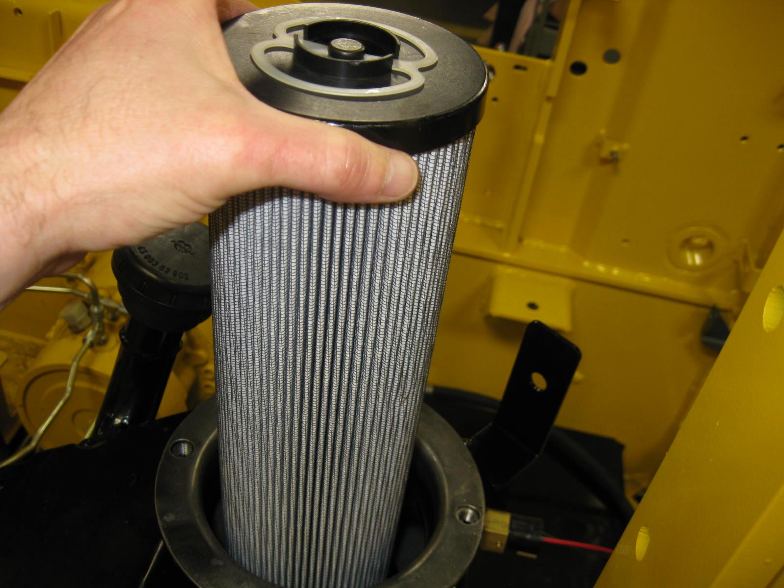
5.Remove four bolts on the cover plate and remove the plate and spring.
6.Pull up on the filter element and remove it from the reservoir (Fig.20).
7.Apply a small amount of hydraulic oil to the o-ring at the bottom of the new filter and install the new filter element in the reservoir.
8.After properly positioning the spring, reinstall the cover plate and its hardware.
9.Refill the hydraulic oil reservoir with oil (if needed). Refer to the Lubrication chart (page76).
Changing Hydraulic Oil
The hydraulic oil must be replaced if it becomes contaminated, after major repairs and after 1000 hours or one year of use.
1.Under the machine near the left rear tire, unbolt a small left rear floor plate cover to access the drain plug.
2.Install a catch pan of sufficient capacity under the oil reservoir. See page76.
3.Remove the drain plug on the reservoir tank and allow the oil to drain (Fig.21).
4.Reinstall the drain plug and floor plate cover.
5.Change the oil filter.
6.Refill the reservoir. Refer to the Lubrication chart (page76).
7.Start the engine and operate the hydraulic controls.
8.Stop the engine and check for leaks at the filter and reservoir drain plug.
9.Check the fluid level and add fluid, if needed.
Bucket Cutting Edge
The bucket cutting edge should be replaced when it is worn to within 1in. (25mm) of the bucket body.
Alternator Belt
Refer to the separate engine manual for setting proper belt tension. If the belt is worn, cracked or otherwise deteriorated, replace the belt following the procedure in the engine manual.
Wheel Nuts
Wheel nut torque must be checked before initial operation and every two hours thereafter until the wheel mounting hardware torque remains at 240ft.-lbs. (325N·m). When wheels are removed and reinstalled this procedure must be repeated.
Lift Arm Pivots
The Power-A-Tach® pivot should be torqued every 250 hours to 380 ft.-lbs. (515 N·m). Refer to the Maintenance Interval Chart (page115).
Cooling System
Important: Check the cooling system daily to prevent overheating, loss of performance and engine damage.
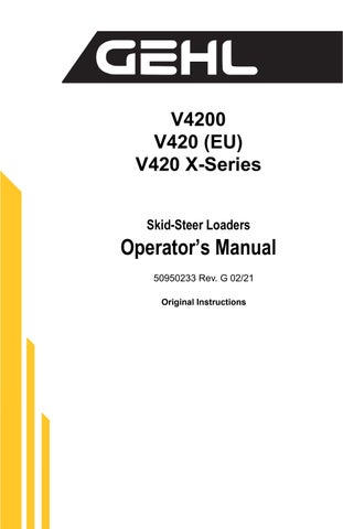
Checking Coolant Level
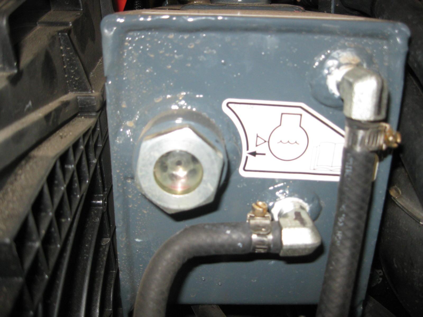
1.With the engine at operating tempera ture, open the engine cover. Looking at its visual sight gauge, check that the coolant tank fluid is half way up on the sight glass of the coolant tank (Fig.22).
2.Allow the coolant to cool. Do not remove the cap when the coolant is hot. Serious burns may occur.
3.Add premixed coolant meeting Deutz CB-14 approval to the tank if the coolant level is low.
Cleaning the Cooling System
Warning
Allow sufficient time for the oil radiator to cool before working on or near it. Parts get extremely hot during operation and can burn you.
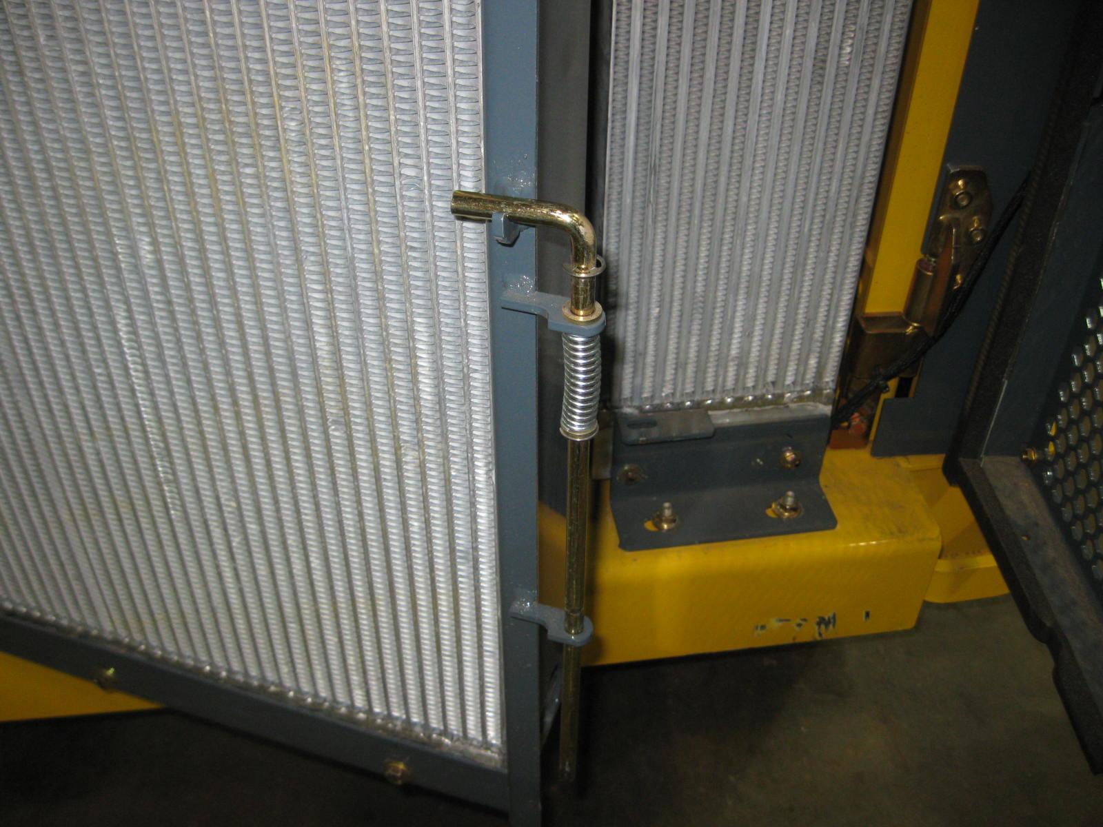
The radiator assembly is mounted between the engine and the hinged rear door. When operating correctly, air is blown through the openings between the fins by the engine fan. During operation dust and debris can build up on the engine side of the radiator and restrict air flow through the fins. To remove this restriction, use compressed air and direct the flow through the fins from the rear of the radiator toward the engine.
1.Lower the lift arm and stop the engine. Allow the machine to cool.
2.Raise the engine cover and open the rear door (page73).
3.Pull up on the radiator lock pin and put it in its placeholder (Fig.23), then swing the radiator out (Fig.4).
4.As necessary, clean the radiator and air cooler by blowing compressed air through the fins from the rear, toward the engine.
Draining/Flushing the Cooling System
1.Lower the lift arm and stop the engine. Allow the machine to cool.
2.Raise the engine cover and open the rear door (page73).
3.Remove the radiator cap on the coolant tank (Fig.22).
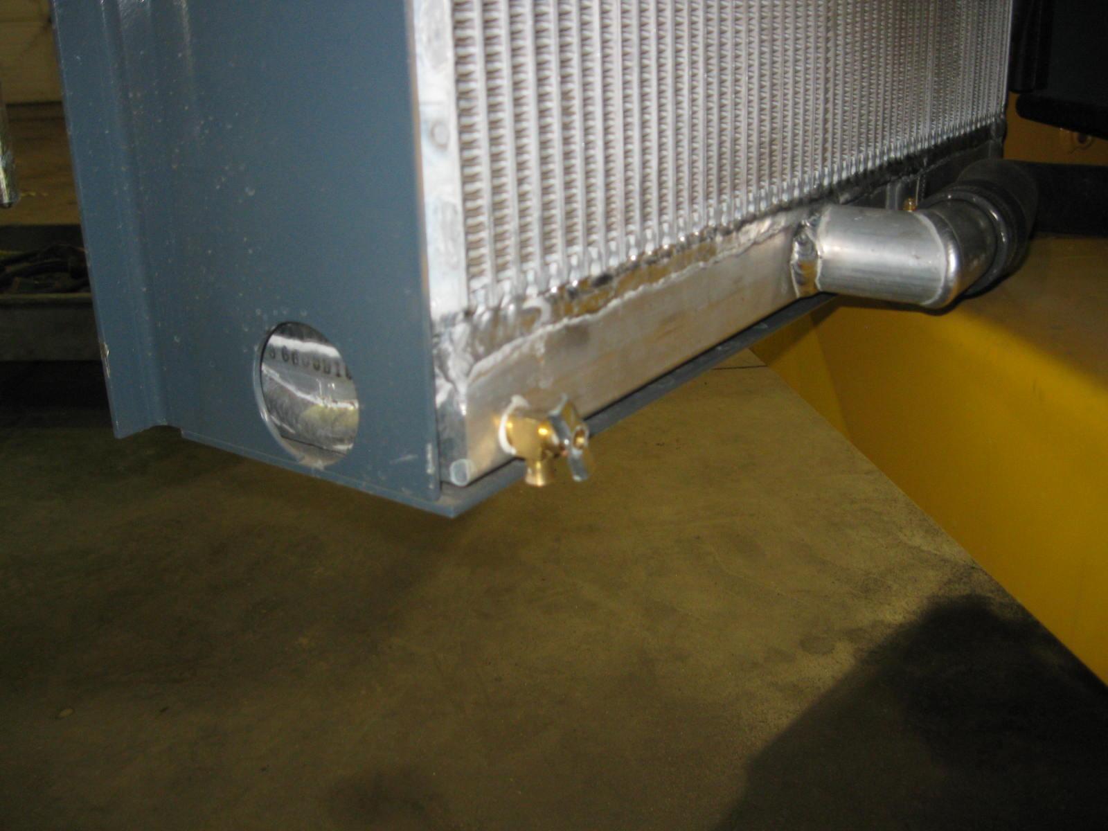
4.Open the drain cock on the radiator (Fig.24) and drain the coolant into a suitable container.
Note: Coolant must be drained from the radiator and the engine.
5.Close the drain cock.
Note: Protect the cooling system by adding premixed coolant meeting Deutz CB-14 approval to the tank if the coolant level is low.
6.Fill the radiator fully and the coolant tank to half full.
7.Reinstall the radiator cap and run the engine until it is at operating temperature.
8.Stop the engine and let it cool. Check the coolant level. Add more fluid, if necessary.
Tires
Inflating or servicing tires can be dangerous. When possible, trained personnel should service and mount tires. To avoid possible death or serious injury, follow the safety precautions below.
Warning
To keep tire wear even, rotate the tires from front to rear and rear to front.
It is important to keep the same size tire on each side of the machine to prevent excessive wear on tires, chains, or other damage. If different sizes are used, tires will be turning at different speeds, causing excessive wear.
Note: The tread bars of all tires should point the same direction.
BE SURE the rim is clean and free of rust.
Lubricate the tire beads and rim flanges with a soap solution. Do NOT use oil or grease.
Use a clip-on tire chuck with remote hose and gauge, allowing you to stand clear while inflating the tire.
NEVER inflate beyond 35 psi (240 kPa) to seat the beads. If the beads have not seated by the time the pressure reaches 35 psi (240 kPa), deflate the assembly, reposition the tire on the rim, lubricate both parts and re-inflate.
Inflation pressure beyond 35 psi (240 kPa) with unseated beads may break the bead or rim with explosive force sufficient to cause death or serious injury.
After seating the beads, adjust the inflation pressure to the recommended operating pressure.
Do NOT weld, braze or otherwise attempt to repair and use a damaged rim.
Checking Tire Pressure
Correct tire pressure should be maintained to enhance operating stability and extend tire life. Refer to the chart below for proper inflation pressures.
Tire Size
Heater/Air Conditioner Filters
The optional heater and heater/air conditioner include two filters: fresh air intake and recirculation air.
Filters should be replaced as needed.
Fresh Air Intake Filter: Located directly behind the cover on the HVAC (heating, ventilating and air conditioning) housing mounted on the upper rear corner of the cab. Remove the threaded knobs on both sides of the cover to access the filter.
Recirculation Air Filters: Located behind the covers in the headliner directly above the rear window. The access, remove the screws on either side of the covers.
Important: Keeping the cab clean will reduce need for service and help ensure proper air conditioner and heater operation. Failure to do so can cause evaporator and heater core plugging, fan noise, vibration and failure.
Electrical System
Fuse Panels
The main fuse panels (Fig.25) are located behind two covers in the operator’s compartment directly behind the operator’s foot area, as well as the electrical engine disconnect switch.
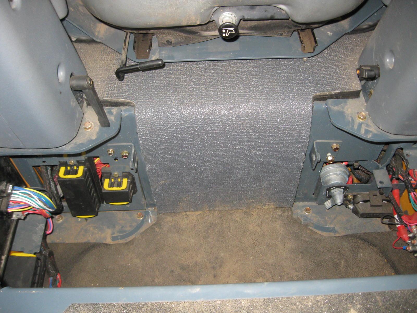
Shown below are the decals for the fuse covers in this area.
The left side fuse decal is for Diesel Exhaust Fluid ((DEF) / Selective Catalytic Reduction (SCR) enabled machines.
The right side fuse decal is for machines that do not have DEF/SCR functions.
Battery
Before servicing the batteries or electrical system, be sure the electrical engine disconnect switch is in the OFF position or disconnect the negative (ground) battery cable.
Warning
The batteries on the machine are 12-volt, group 24, wet-cell batteries. To access the batteries, remove the floor mat and pull up on the center foam cover (Fig.25) between the control handles to release it from its fasteners, then remove the metal cover beneath the crossmember.
The battery top must be kept clean. Clean it with an alkaline solution (ammonia or baking soda and water). After foaming has stopped, flush the battery top with clean water. If the terminals and cable connection clamps are corroded or have a build-up, disconnect the cables and clean the terminals and clamps with the same alkaline solution. Apply protective spray to prevent corrosion.
Warning
Explosive gas is produced when a battery is in use or being charged. Keep flames and sparks away from the battery area. ALWAYS charge the battery in a well-ventilated area.
Never lay a metal object on top of a battery, because a short circuit can result.
Battery acid is harmful on contact with skin or fabrics. If acid spills, follow these first-aid tips:
1.Immediately remove any clothing on which acid spills.
2.If acid contacts the skin, rinse the affected area with running water for 10 to 15 minutes.
3.If acid contacts the eyes, flood the eyes with running water for 10 to 15 minutes. See a doctor at once. Never use any medication or eye drops unless prescribed by the doctor.
4.To neutralize acid spilled on the floor, use one of the following mixtures: a.1 pound (0.5 kg) of baking soda in 1 gallon (4 L) of water, or b.1 pint (0.5 L) of household ammonia in 1 gallon (4 L) of water
Whenever a battery is removed, be sure to disconnect the negative (-) battery terminal connection first.
Diesel Exhaust Fluid (DEF) Service (If So Equipped)
Diesel Exhaust Fluid (DEF) Level
The DEF level (F, Fig.26) is shown on the multi-function display. The DEF symbol will appear on the multi-function display when the DEF tank level reaches 15%. The symbol will begin flashing when the DEF level falls below 10%. If the level falls below 5%, a warning tone will be activated and an additional warning light will activate. If the DEF tank is still not filled, the warnings and an alarm tone will continue. Additionally, the engine will begin to de-rate to IDLE and reduce engine power.
DEF fluid quality is also monitored. DEF fluid meeting ISO 22241 must be used for this machine. If the DEF quality is not correct, an error symbol will appear on the multi-function display and the engine will de-rate if the DEF fluid quality is not remedied within a certain period of time.
The DEF fluid reservoir filler is located behind a latched cover at the rear right side of the chassis.
DEF Dosing Unit Filter Replacement
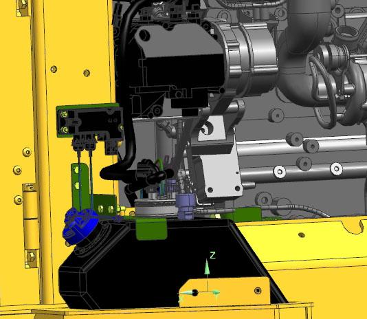
The DEF dosing unit is located above the DEF reservoir tank. Inspect the area around the seal and vent of the aftertreat ment DEF dosing unit filter cap for signs of leakage.
Note: DEF leaks are indicated by white deposits. 50950233/
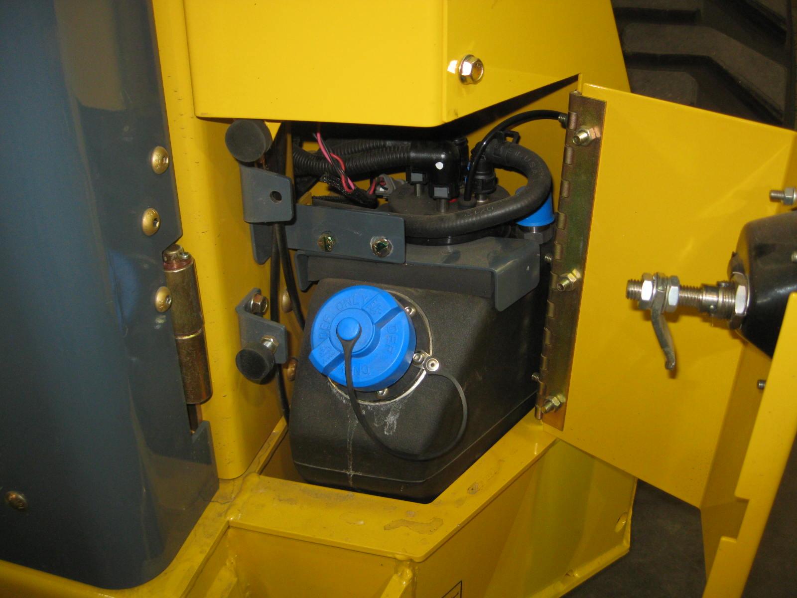
The DEF dosing unit (Fig.28) is located above the reservoir tank, behind the right rear engine cover panel. Inspect the area around the seal and vent of the aftertreatment DEF dosing unit filter cap for signs of leakage.
Note: DEF leaks are indicated by white deposits.
Diesel exhaust fluid (DEF) contains urea. Avoid eye contact. In case of eye contact, immediately flush eyes with large amounts of water for a minimum of 15 minutes. Do not swallow DEF. In the event that DEF is ingested, contact a physician immediately. Reference the Materials Safety Data Sheet (MSDS) for additional information.
Warning Warning
Do not disconnect the DEF line between the aftertreatment DEF dosing unit and the dosing valve while the machine is running or for some time after engine shutdown. Pressure in the line could cause ejection of DEF fluid. Shut off the machine and allow at least five minutes for the system to complete the purge cycle before disconnecting the DEF line.
Note: Do not disconnect the batteries until the DEF dosing system has completed the purge cycle. Before performing any maintenance on the DEF system, wait at least five minutes after shutting off the machine for the aftertreatment DEF dosing system to purge DEF from the system. The purge cycle occurs automatically; a pumping noise can be heard during the purging process.
1.Remove the right rear engine cover panel to access the DEF dosing system.
2.Place a collection container below the filter cap to collect any residual DEF in the filter housing.
3.Unscrew the DEF filter cap.
Note: A 27 mm wrench can be used on the cap to aid in its removal.
4.Check the condition of the DEF dosing unit cap. Replace the cap if the cap has cracks or holes that could create a DEF leak path and/or if the cap threads are damaged.
5.Inspect the threads on the aftertreatment DEF dosing unit casing. This is especially important if the aftertreatment DEF dosing unit cap was damaged. If the aftertreatment DEF dosing unit casing threads are damaged, replace the entire aftertreatment DEF dosing unit.
6.Remove the aftertreatment DEF filter equalizing element (O, Fig.29) and discard.
7.Remove the old aftertreatment DEF dosing unit filter element (P, Fig.29).
Note: A disposable service tool is included with the filter to aid in filter removal. Refer to the instructions included with the replacement filter. Use the appropriate end of the tool, depending on the color of the plastic on the filter. When inserting the tool, a “click” sound can be heard which indicates a proper engagement with the filter.
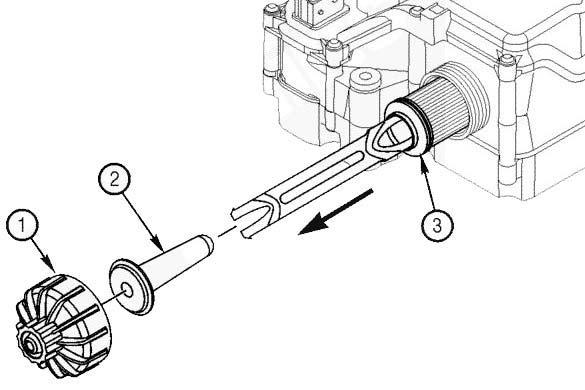
Important: If the filter element and equalizing element are removed from the aftertreatment DEF dosing unit, they must be discarded and replaced, regardless of condition.
8.Slide a new DEF filter equalizing element (O) into the DEF filter cartridge (P). Insert the assembly into the aftertreatment DEF dosing unit.
9.Clean the aftertreatment DEF dosing unit cap and threads on the dosing unit with warm water and a clean cloth.
10.Install and tighten the cap (M). A 27 mm wrench can be used to install and tighten the filter cap. Torque the cap to 20 NM (177 in-lb).
Important: Never operate the machine with the DEF cap removed.