2 minute read
Engine Service

from Gehl V4200 V420 (EU) V420 X-Series Skid-Steer Loaders Operator’s Manual 50950233 - PDF DOWNLOAD

Refer to the Maintenance Interval chart (page115) for change intervals.
Refer to the Engine Operator’s Manual for detailed engine information.
Checking Engine Mounting Hardware
All bolts that secure the engine mounting brackets to the engine and the machine frame should be checked and re-torqued as necessary. Refer to the Torque Specifications Chart (page127) for torque information.
Warning
Allow hot engine and hydraulic system components to cool before servicing.
Checking Engine Oil Level
Open engine cover (page 73), pull out the dipstick and check the oil level. Markings on the dipstick represent FULL and LOW (add oil) levels.
Changing Engine Oil and Filter
Engine oil and filter service every 250 hours or every 500 hours depending on type of oil used.
NOTE: Follow specifications in the Lubrication Chart on (page 77) for type and viscosity of new oil to use for the change interval.
Important: Always dispose of waste lubricating oil according to local regulations or take to a recycling center for disposal; do not pour onto the ground or down the drain.
Raise the lift arm and engage the lift arm support device as described in the “Lift Arm Support Device” on page28.
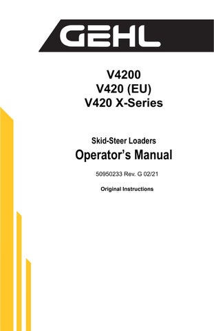
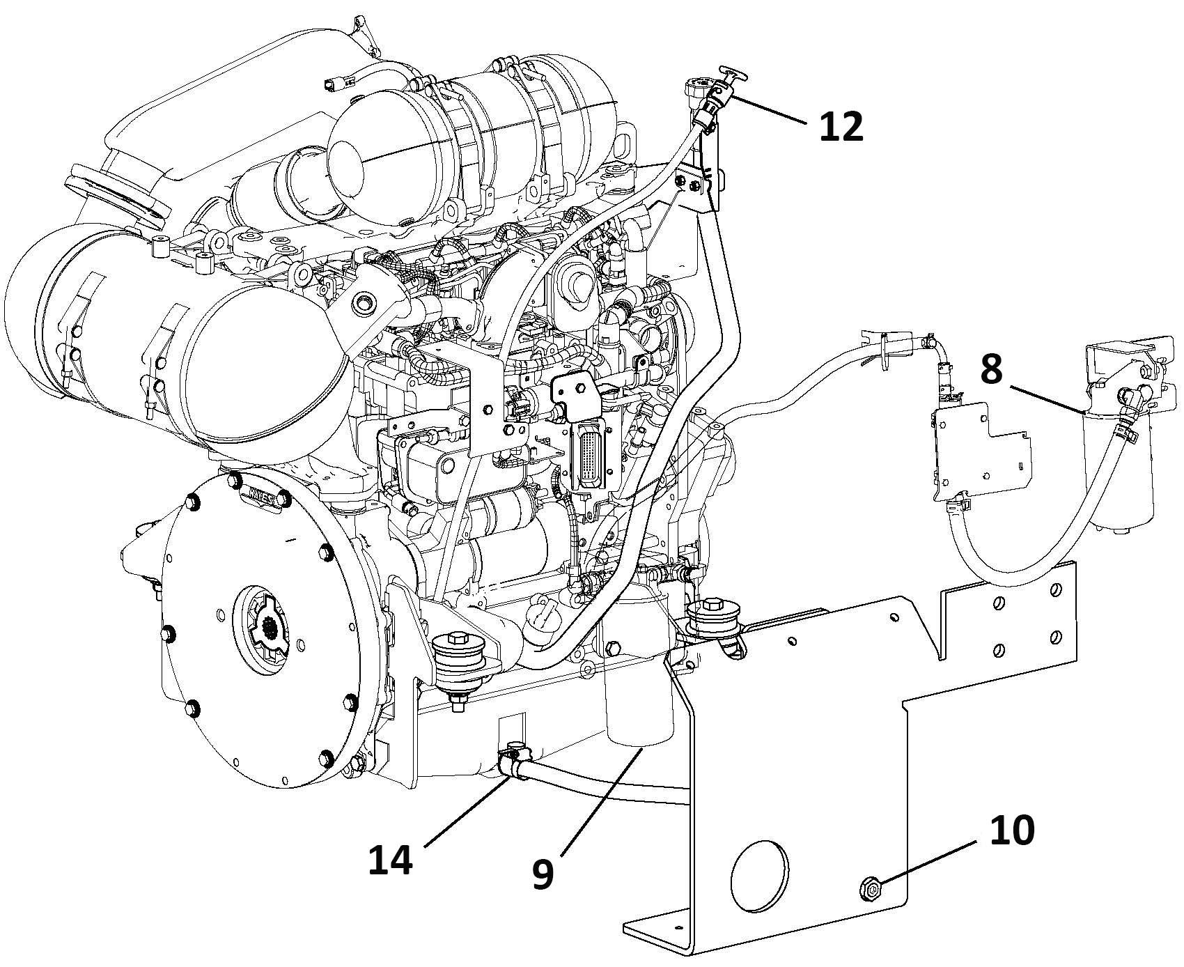
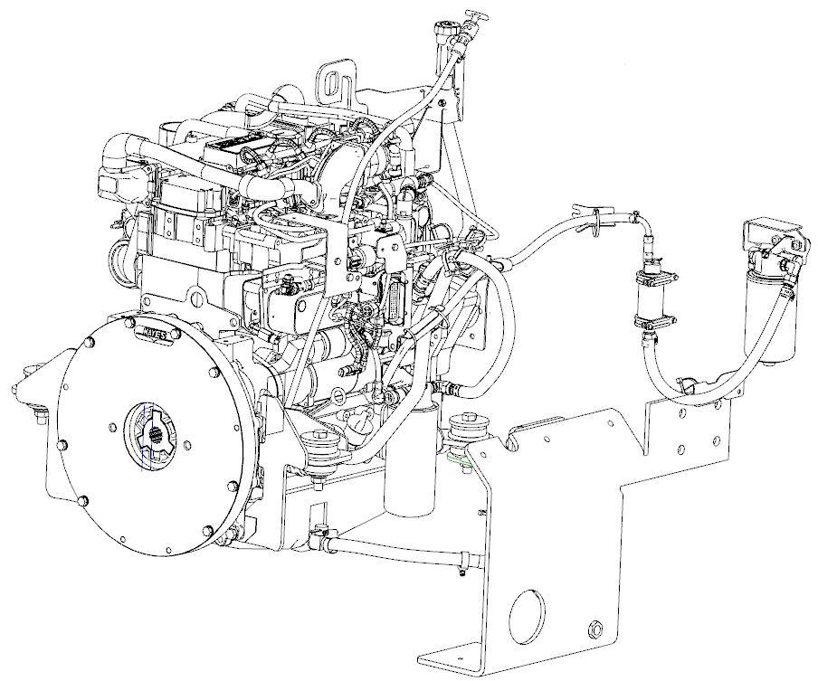
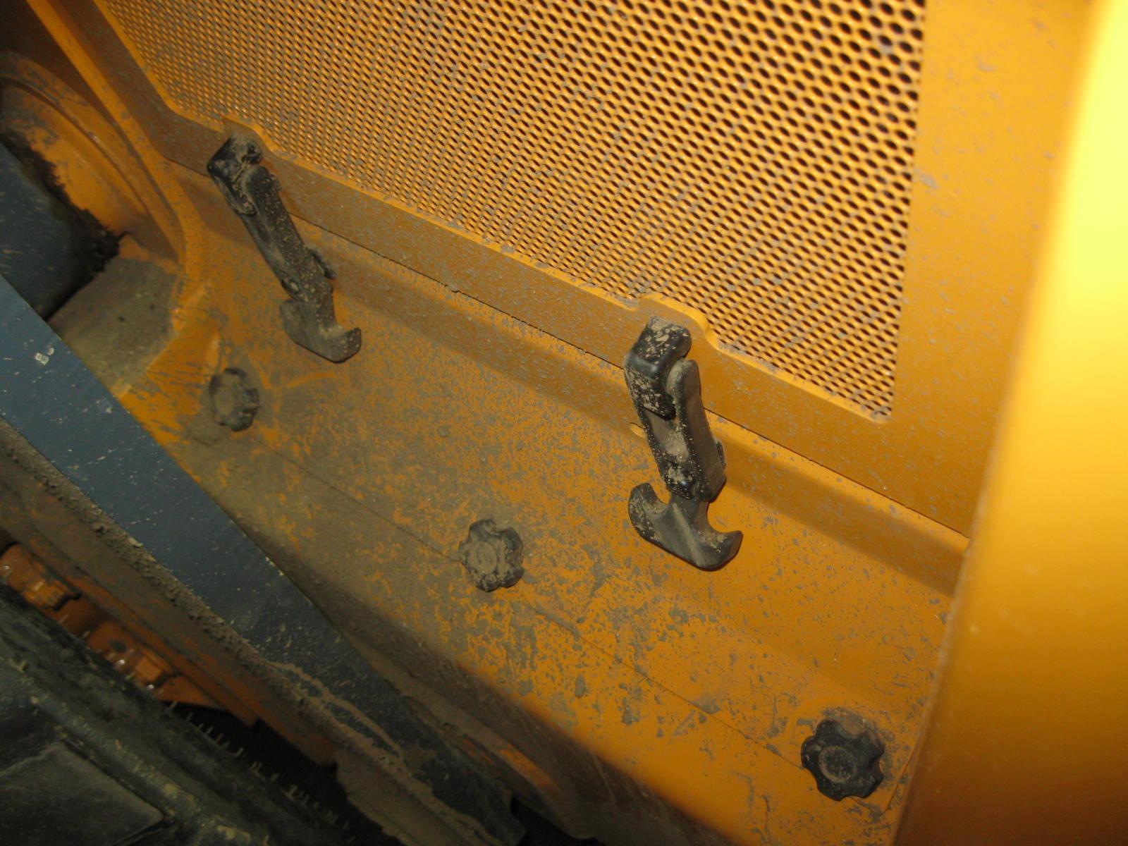
The engine oil filter is located on the left side of the engine. Access the filter by removing the left rear access panel (two rubber latches) and the lower access plate (Fig.13).
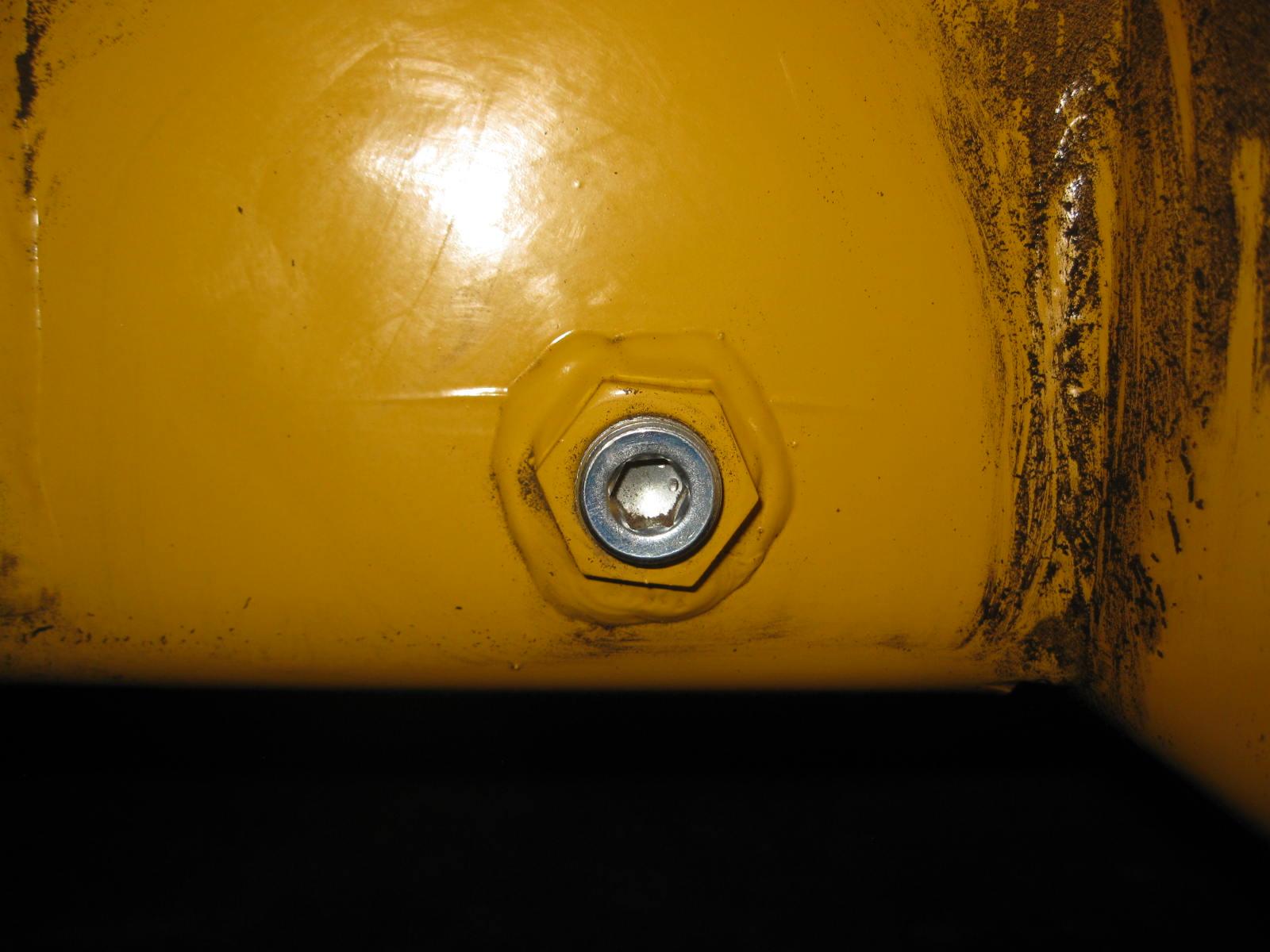
Access for draining the engine oil is located on the lower rear left side of the chassis (Fig.14).
Drain oil by first removing the plug. Follow the drain line to the engine; lift and turn the interior drain valve 1/4 turn counterclockwise to allow oil to drain out. After draining the oil, turn the drain valve at the engine 1/4 turn clockwise and reinstall the plug.
To add new oil, open the engine access cover. Remove the oil fill cap and add the recommended type and quantity of oil. Refer to the Lubrication chart, page76. Visually inspect the remote oil drain hose for damage or leaks.
Changing Fuel Filter
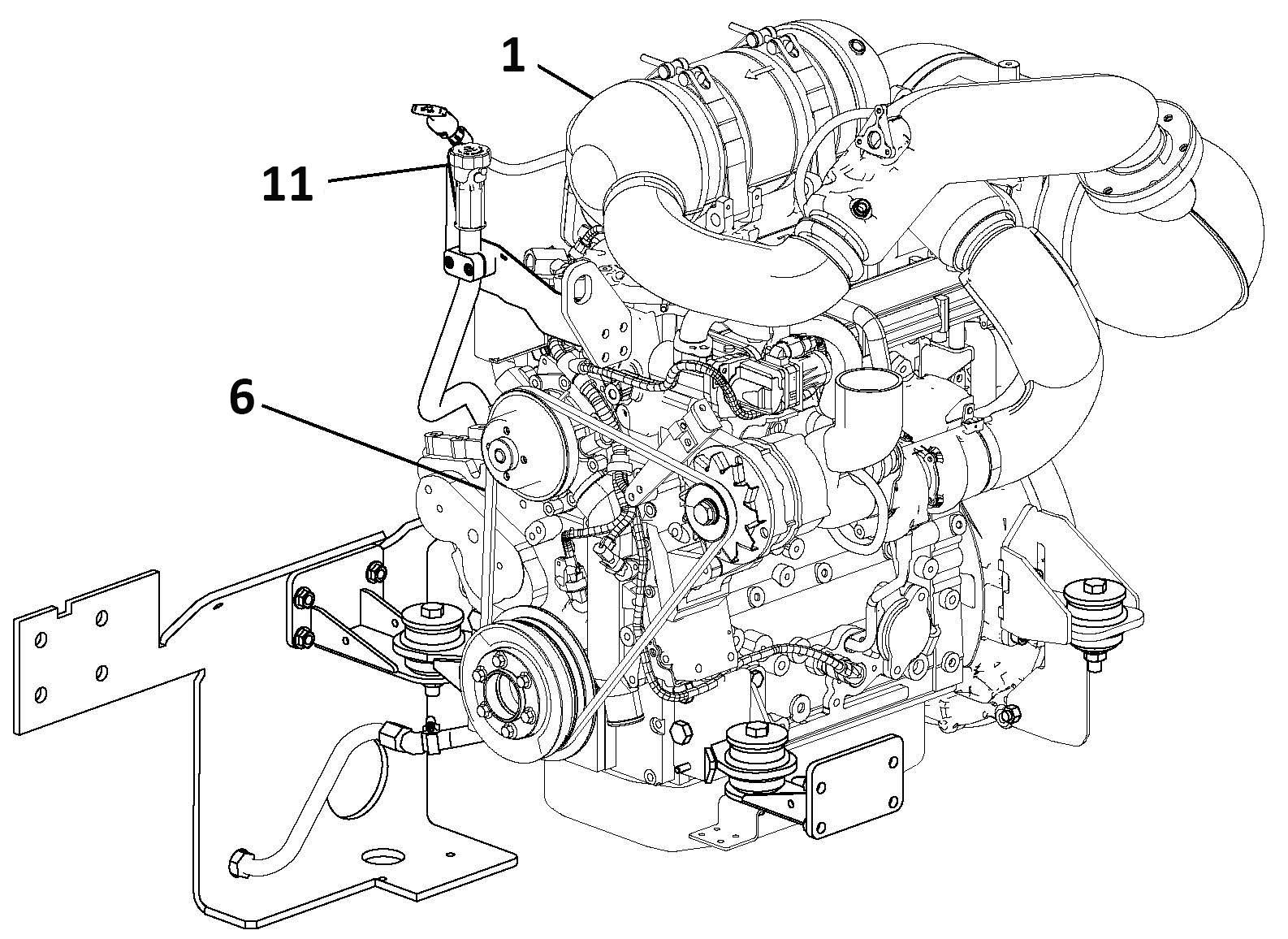
The fuel filter is located on the left side of the engine, near the oil filter. Unlatch the left engine access panel to access the filter and clean dirt from around the filter head. Remove the filter from the engine. Replace with a new filter element. Lubricate the seal on the new filter element with fuel before installing. Turn the keyswitch to the ON position for three minutes to fill the filter via the electric fuel pump. Start the engine and check for leaks. See page82 for location on the engine.
Checking the Water Separator
The water separator is located above the fuel fill cap. Check on a daily basis and drain if necessary. If excess water collects in the separator an alarm will be shown on the multi-function display. Water can be drained from the separator by opening the valve located at the bottom of the sep arator bowl.
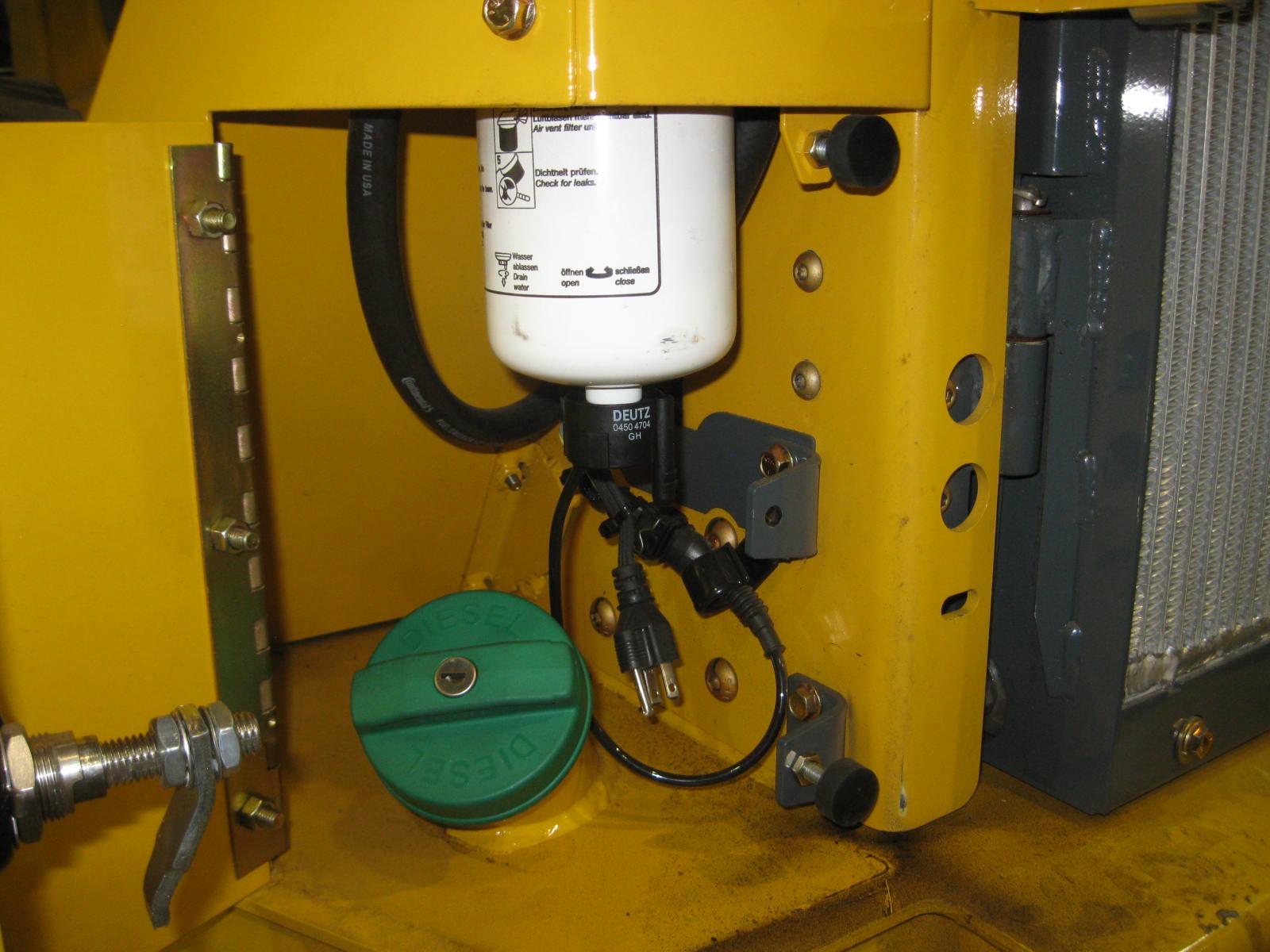
Note: A water-in-fuel sensor leading from the bottom of the separator may need to be unplugged to open the valve.
After draining the separator, turn the key switch to the ON position for three min utes to fill the filter via the electric fuel pump.
Engine/Machine Diagnostic Charts
When detecting faults, the multi-function display (page35) uses a diagnostic trouble code (DTC) screen to alert the operator to the occurrence of the fault conditions.
The data port for the engine is located inside the cab behind the seat and on the right side of the operator’s seat.

The data port for the machine is located inside the cab behind the seat and on the left side of the operator’s seat.
The following pages list descriptions, diagnostic trouble codes and fault codes for the engine and machine.
As an additional reference, Deutz engine trouble diagnostic codes can be found at this website: http://serdia.deutz.com/Service/Technik/Servicedoku/sis_publ.nsf/ gestaltungsdokumente/serdia2010/. Click on the Deutz trouble code list EMR4_DE_EN.pdf file.