11 minute read
Table 5: Control Keypad Indicators

from Gehl V4200 V420 (EU) V420 X-Series Skid-Steer Loaders Operator’s Manual 50950233 - PDF DOWNLOAD

ItemIndicatorDescription
Details
A High-Speed Travel Range IndicatorIndicates high-speed travel range is activated.
B Lift Arm Float Indicator Indicates lift arm float is activated.
C Hydraglide™ Indicator Indicates HydraglideTM lift arm cushion is activated.
DEngine Pre-heat Indicator
Is lit when ignition keyswitch is in the ON/RUN position and engine pre-heat is required; goes out when engine pre-heat is complete.
ESeat Belt Reminder Indicator Is lit when ignition is turned on as a reminder to lower the safety bars and fasten the seat belt.
F Battery Voltage Warning Indicator Indicates battery charging system malfunction. During normal operation this indicator should be OFF.
G Engine Air Filter Restriction Indicator
H Hydraulic Oil Filter Warning Indicator
I Hydraulic Oil Temperature Warning Indicator
J Engine Malfunction Indicator
K Coolant Temperature Warning Indicator
L Engine Oil Pressure Warning Indicator
Indicatesengineairfilterrequires service. See “EngineAir Cleaner”. During normal operation this indicator should be OFF.
Indicates hydraulic oil filter requires service. See“Changing HydraulicOil Filter”. Duringnormal operation thisindicator shouldbe OFF.
Indicates hydraulic temperature is too high. During normal operation this indicator should be OFF.
Is lit when the engine electronic control unit (ECU) hasdetected an errorcondition. Refer to “Engine Diagnostic Trouble Codes (DTC)”.
Indicates coolant temperature is too high. During normal operation this indicator should be OFF.
Indicates engine oil pressure is too low. During normal operation this indicator should be OFF.
IMPORTANT! Immediately shut down the engine if this indicator is lit. Correct the problem before restarting the engine.
Instrument Panels
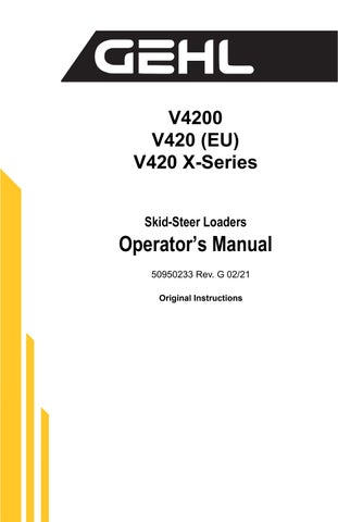
Left Panel
A. A/C Indicator (option) – Illu minates when the air conditioning is operational.
B. Heat Indicator (option) – Illu minates when the heater is opera tional.
C. HVAC Button – Turns the fan/ heat/cool on/off. Low, medium and high settings are available.
D. Fan Button – Turns the fan on/ off. Low, medium and high settings are available.
E. Front Windshield Wiper But ton (option) – Turns the windshield wiper button on/off. Low, medium and high settings are available.
F. Front Windshield Washer (option) – Activates the windshield washer.
G. Rear Windshield Wiper Button – Turns the windshield wiper button on/ off. Low, medium and high settings are available.
H. Rear Windshield Washer (option) – Activates the windshield washer.
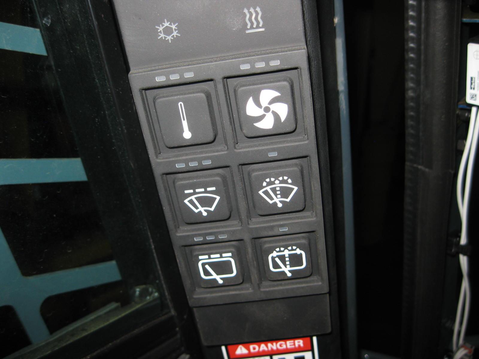
Right Panel
A. Multi-Function Display – See page35.
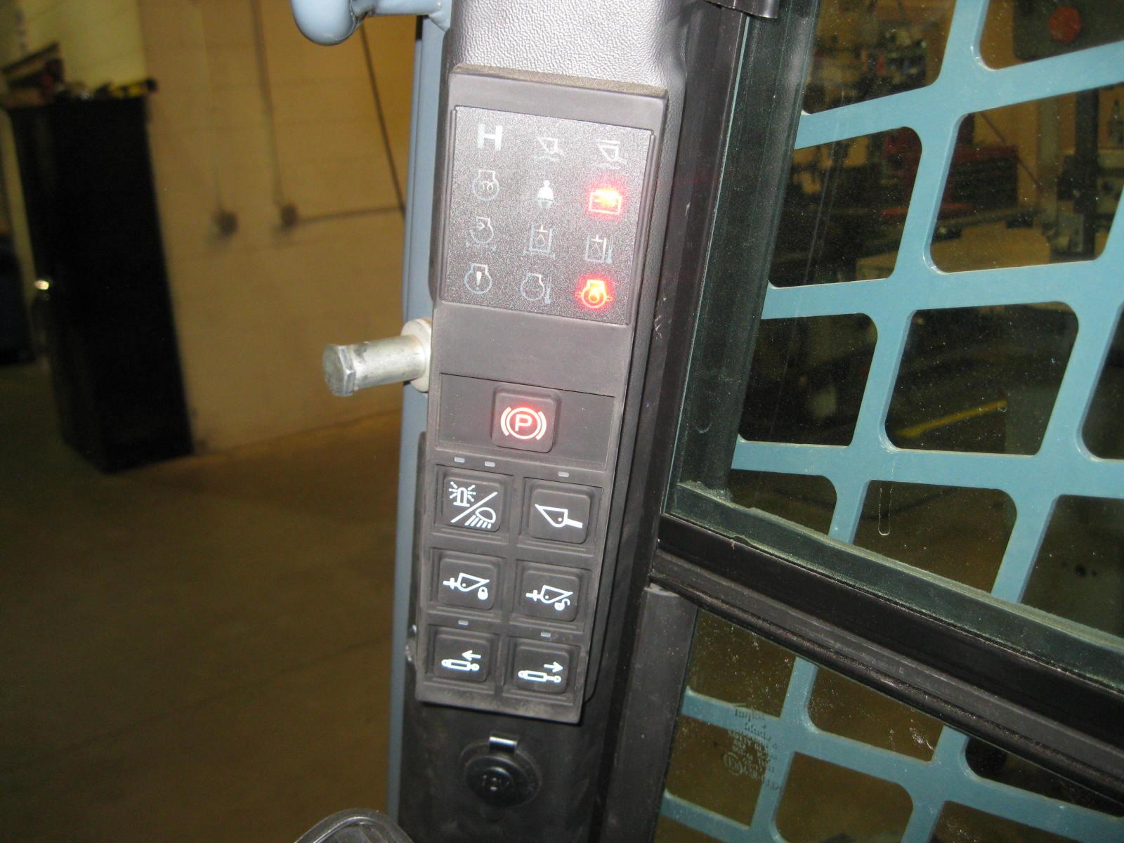
B. Keyswitch – In a clockwise rota tion, the positions are:
• OFF Position – With the key vertical, power from the bat tery is disconnected from the controls and instrument panel electrical circuits. This is the only position from which the key can be inserted or removed.
• ON (or RUN) Position
With the key turned one posi tion clockwise from vertical, power from the battery is supplied to all control and instrument panel circuits.
• START Position – With the key turned fully clockwise, the electric starter engages, to start the engine. Release the key to RUN position after the engine starts.
Note: The engine cannot be started unless the operator is sitting in the seat and the restraint bar is lowered.
C. Engine Speed Control – Con trols the engine speed. Move the con trol clockwise to increase and counter-clockwise to decrease the engine speed.
D. Indicator Panel - See page42.
E. Parking Brake Switch – Used to manually apply, on release, the parking brake. Lights when the park ing brake is applied.
F. Beacon/Work Light Button
Activates optional beacon and/or work lights. Illuminates when the beacon or work lights are on.
G.Self-Leveling Cancel Button
Press the top of the switch to deacti vate self-leveling. Press the bottom of the switch to restore the self-leveling function. Illuminates when self-level ing is deactivated.
H. Power-A-Tach System Hitch Lock Button - Press and hold to lock attachments onto the hitch.
I. Power-A-Tach System Hitch Unlock Button - Press and hold to unlock attachments from the hitch.
J. High-Flow Auxiliary Hydrau lics Reverse Flow Button - Press to activate reverse auxiliary hydraulics flow.
K. High-Flow Auxiliary Hydraulics Forward Flow Button - Press to activate forward auxiliary hydraulics flow.
L. 12V Accessory Plug - For multiple uses.
Warning
Be sure the joystick controls are in neutral before starting the engine. Operate the controls gradually and smoothly. Excessive speed and quick control movements without regard for conditions and circumstances are hazardous and could cause an accident.
Joystick Controls
The machine is equipped with dual joystick controls, (Fig.21). The left joystick controls the drive, and the right joystick controls the lift/tilt.
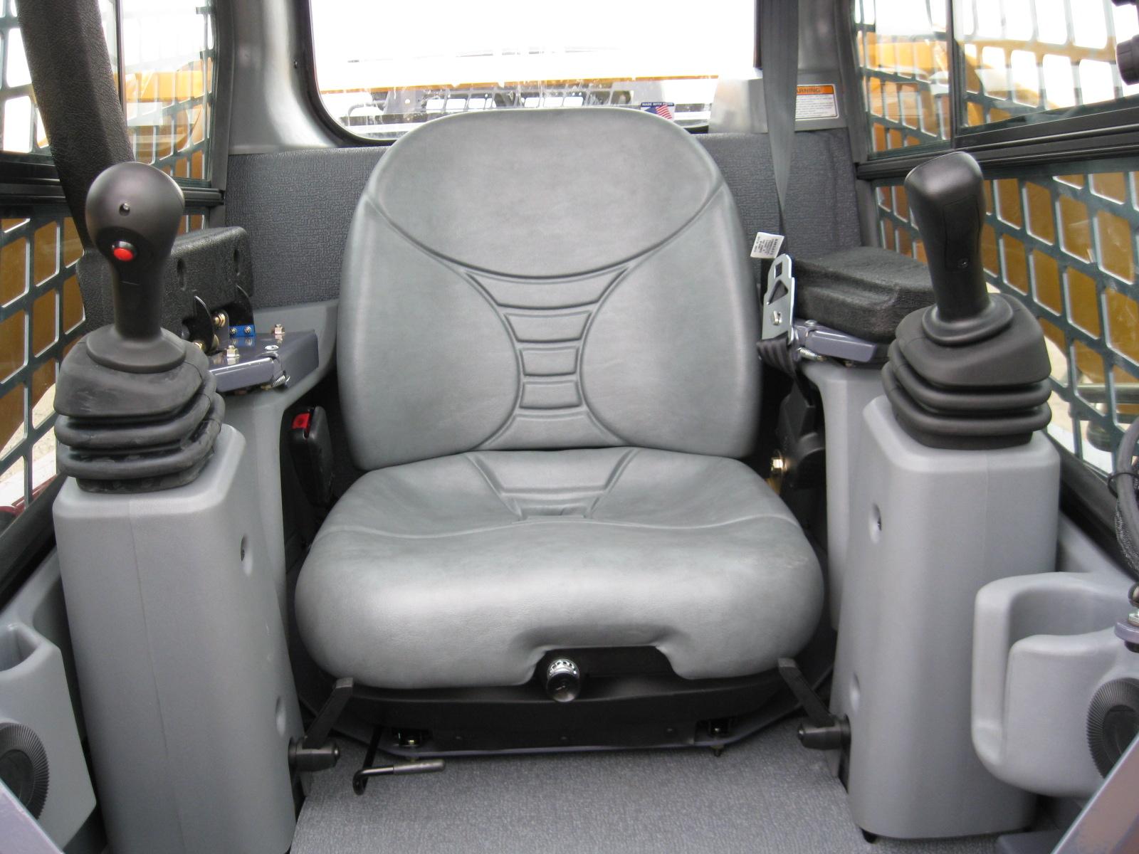
Drive Controls
Forward, reverse, speed and turning maneuvers are accomplished by movement of the left joystick. To go forward, push the drive control forward; for reverse, pull the control rearward. To turn right, push the control right; to turn left, push the control left. To go forward and left, move the control forward and left. To go forward and right, move the control forward and right. To move back and left, move the control back and to the right. To move back and right, move the control back and to the left.
Moving the joystick further from neutral increases the speed steadily to the maximum travel speed. Tractive effort decreases as speed increases. For maximum tractive effort, move the joystick only slightly away from the neutral position. The engine may stall if the control is moved too far forward when loading the bucket.
Lift/Tilt Control
Moving the lift arm and tilting the attachment are accomplished by movement of the right joystick. To raise the lift arm, pull the control straight rearward; to lower the lift arm, push the control straight forward. To tilt the attachment forward and downward, move the control to the right; to tilt the attachment up and back, move the control to the left.
Note: The speed of the lift/tilt motion is directly proportional to the amount of joystick movement and engine speed.
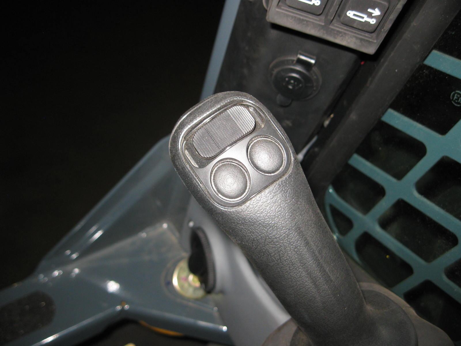
To place the lift arm into the “float” position, push and hold the top left button on the right joystick. This mode allows the lowered lift arm to follow the ground contour while traveling over changing ground conditions. An indicator lamp in the left instrument panel will blink when float is activated.
Warning
Never push the float control button with the attachment raised, because this will cause the lift arm to lower very rapidly.
Releasing the float button will cancel the float mode if the button was pressed less than five seconds. If the float mode button is pressed longer than five seconds, the float feature will stay on and the float indicator lamp will stay lighted until the button is pressed again or the machine is turned off.
Auxiliary Hydraulic System
Auxiliary hydraulics are used with attachments that have a mechanism requiring hydraulic power.
Always be sure the auxiliary hydraulic control is in neutral before starting the machine or disconnecting the auxiliary hydraulic couplers.
Standard-Flow Auxiliary Hydraulic Control
Machines are equipped with a standard-flow auxiliary hydraulic system with flatface couplers. The couplers are located on top of the lift arm on the left side. The black rocker switch located on the right-hand control controls the direction and amount of flow. The farther the switch is moved from center, the higher the flow to the auxiliary circuit. The direction of flow is reversed when the rocker switch is moved in the opposite direction from the center. Pushing the switch to the right will pressurize the standard auxiliary male cou pler. For continuous operation, move the switch in either direction and push the trigger button, located on the front of the grip for five seconds, and release. To cancel continuous operation, push the button or move the black switch in either direction.
High-Flow Auxiliary Hydraulic Control
In addition to a standard-flow auxiliary hydraulic system, machines are equipped with a reversible high-flow auxiliary hydraulic system. The couplers are located on top of the right lift arm. The high-flow auxiliary hydraulic system is used for operating certain hydraulic attachments (e.g., cold planer, snow blower) that require higher flows.
The high-flow auxiliary switch controls the direction of hydraulic oil flow. Push the right button for forward flow or the left button for reverse flow. Pushing the right button will pressurize the high-flow male coupler. To disengage, push and release the button. Turning off the machine, raising the restraint bar, or restarting the engine will also reset the high-flow to neutral. A LED light above the buttons will illuminate when the high-flow auxiliary hydraulic system is engaged.
Only connect high-flow attachment couplers to the high-flow auxiliary couplers.
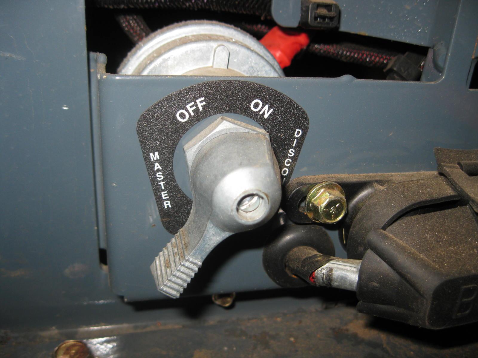
Battery Disconnect Switch
A battery disconnect switch is located at the front of the machine, beneath the left control handle, behind a panel with two turn screws. Turn the switch to the OFF position to disconnect the batteries from the electrical system.
Operation
Before starting the engine and operating the machine, review and comply with all safety recommendations in the Safety chapter of this manual. Know how to stop the machine before starting it. Also, be sure to fasten and properly adjust the seatbelt(s) and lower the operator restraint bar.
Warning
Before Starting the Engine
Before starting the engine and running the machine, refer to the Controls and Safety Equipment chapter and become familiar with the various operating controls, indicators and safety devices on the machine.
Fuel
Deutz will allow up to a 5% (B5) mixture of BioDiesel.
Starting the Engine
The following procedure is recommended for starting the engine:
1.Open the door. Carefully step up onto the back of the bucket or attachment and grasp the handholds to enter the operator’s compartment.
2.Close the door, fasten the seatbelt(s), and lower the restraint bar.
3.Verify the following:
the lift/tilt, drive and auxiliary hydraulic controls are in their neutral positions
the parking brake switch is ON
Note: When the key is turned to the RUN position, an indicator lamp will light on the instrument panel and a buzzer will sound momentarily to remind users to fasten the seatbelt.
4.Turn the key to the START position.
Note: If the temperature is below 32°F (0°C), see the Cold-Starting Procedure on page52.
Important: Do not engage the starter for longer than 15 seconds at a time. Longer use can overheat and damage the starter. If the engine fails to start within 15 seconds, return the key to the OFF position or check for engine error codes. Allow the starter to cool for 20seconds and repeat step 4. If the engine stalls during operation, wait three seconds before restarting the engine.
After the engine starts, allow a five-minute, low idle warm-up period before operating the controls.
Important: If the indicator warning lamps do not turn off, stop the engine and investigate the cause.
Cold-Starting
If the temperature is below 32°F (0°C), the following is recommended to make starting the engine easier:
Replace the engine oil with API-CK-4 and SAE 5W-30 synthetic oil;.
Make sure the battery is fully charged. Let the engine run for a minimum of five minutes to warm the engine and hydraulic fluid before operating the machine.
The standard block heater is recommended for starting in temperatures of 20°F (-7°C) or lower.
Cold-Starting Procedure
Do not use starting fluid (ether) with pre-heat systems. An explosion can result, which can cause injury, death or engine damage.
1.Turn the key to the RUN position. A wait-to-start symbol will appear on the multi-function display. Wait for this symbol to turn off.
2.Turn the key to the START position.
3.If the engine does not start, return the key to OFF position and repeat steps 1 and 2.
Stopping the Machine
Use the following procedure to stop the machine:
1.Be sure that the drive control handle(s) is (are) in neutral position.
2.Lower the lift arm and rest the attachment on the ground.
3.Turn throttle knob back to the low idle position (and release the throttle pedal for joystick and t-bar control machines). Allow the engine to idle for five minutes if the engine was operated under full load.
4.Turn the keyswitch to the OFF position and remove the key.
5.Move the lift/tilt control to verify that the safety interlock system is preventing movement.
6.Raise the restraint bar, unfasten the seatbelt(s) and grasp the handholds while climbing out of the operator’s compartment.
Note: The machine is equipped with a spring-applied automatic parking brake. The parking brake is applied when the operator lifts the restraint bar, leaves the operator’s seat or shuts off the engine, or actuates the parking brake switch.
Parking the Machine
Park the machine away from traffic on level ground. If this is not possible, park the machine across the incline and block the tires to prevent movement.
Brake Release Operation (option)
The machine may have, as an option, a brake release system installed. Utilizing the brake release system disables the parking brake, allowing the machine’s wheels to freely move in either a forward or rearward direction.
Warning
Before utilizing the brake release, be sure to secure the vehicle with wheel chocks or tow lines. Verify the machine’s travel paths are clear of personnel before utilizing the brake release system.
1.Locate the brake release jack and handle, located on the right side of the chassis.
2.Remove any existing access cover.
3.Position the receiver and insert the jack handle.
4.Push the plunger on the receiver and hold.
5.Begin actuating the pump. Hydraulic pressure developed will retain the plunger so it no longer requires to be pushed. Continue to actuate the pump until the resistance of the jack handle does not increase. There is an internal relief valve in the jack assembly that prevents damage to the motor.
6.You may now tow the machine a short distance or pull it onto a trailer. Depending on the drive motor’s internal leakage rate, the machine may roll easily once the brake is released, or the tires may skid until the oil is forced from the motor.
7. The brake can be reset by pulling up on the plunger or starting the machine.
Jump-starting
If the batteries become discharged or do not have enough power to start the engine, use jumper cables and the following procedure to jump-start the engine.
WARNING
The ONLY safe method for jump-starting a discharged battery is for TWO PEOPLE to perform the following procedure. The second person removes the jumper cables so that the operator does not have to leave the operator’s compartment with the engine running. NEVER make jumper cable connections directly to the starter solenoid of either engine. DO NOT start the engine from any position other than on the operator’s seat and then ONLY after being sure ALL controls are in “neutral.”
Closely follow the procedure, in order, to avoid personal injury. In addition, to protect your eyes wear safety glasses and avoid leaning over the batteries while jump-starting.
DO NOT jump-start the batteries if they are frozen because they may rupture or explode.
Note: BE SURE the jumper battery is a 12-volt D.C. battery.
1.Turn the keyswitches of both vehicles to OFF be sure both vehicles are in “neutral” and NOT touching each other.
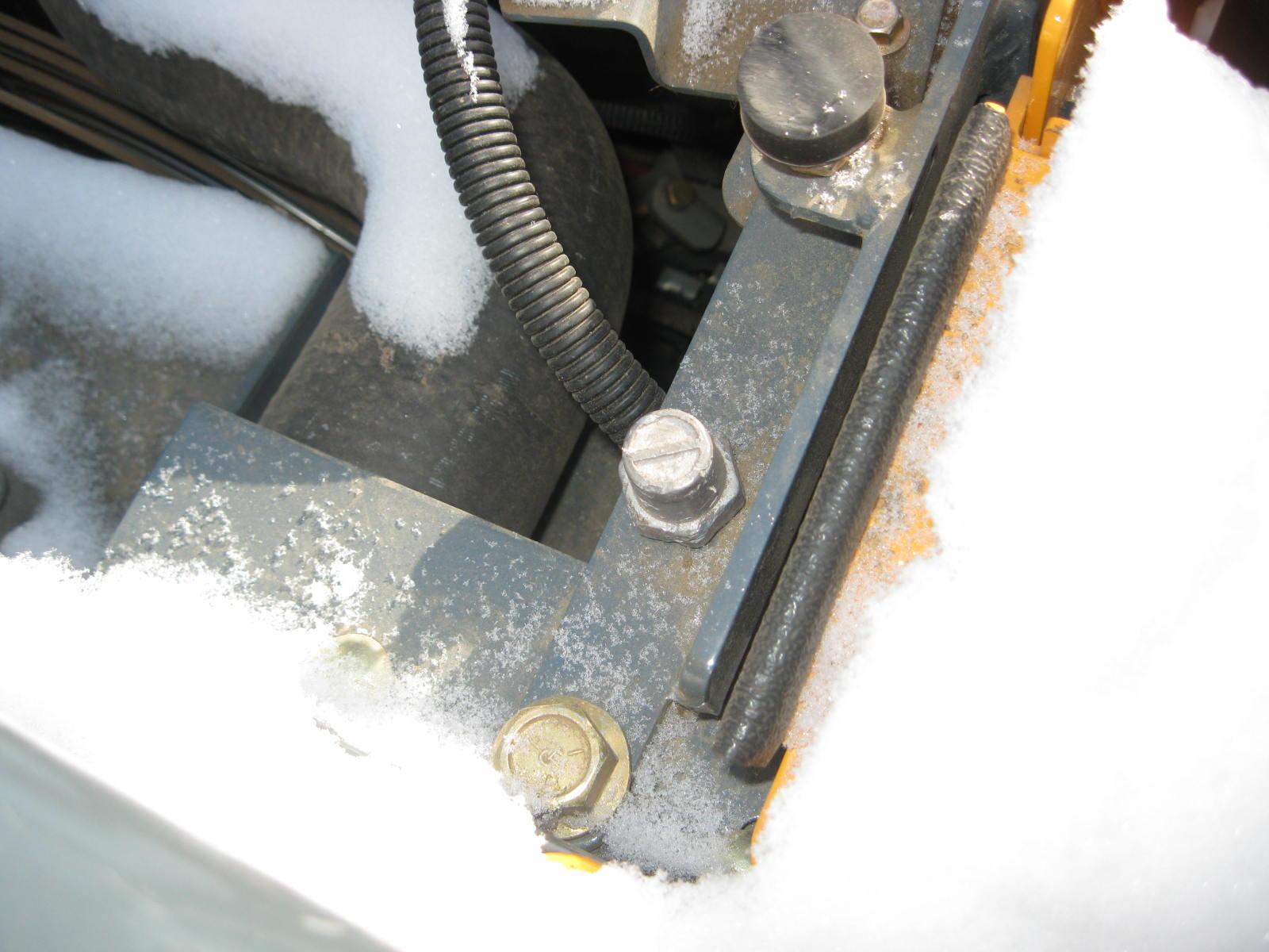
2.Connect the positive (+) jumper cable to the positive (+) remote battery terminal (Fig.1) on the disabled machine first. DO NOT allow the positive clamps to touch any metal other than the positive (+) remote battery terminal.
3.Connect the other end of the positive jumper cable to the jumper vehicle’s battery positive (+) terminal.
4.Connect the negative (-) jumper cable to the jumper vehicle’s battery negative (-) terminal.
5.Make the final negative (-) jumper cable connection to the negative (-) remote battery terminal (Fig.2) on the disabled machine. DO NOT allow the negative clamps to touch any metal other than the negative (-) remote bat tery terminal
6.Start the machine. If it does not start at once, start the jumper vehicle’s engine to avoid excessive drain on the booster battery.
7.After the disabled machine is started and running smoothly, have the second person remove the jumper cables [nega tive (-) jumper cable first] from the jumper vehicle’s battery and then from the disabled machine, while being careful NOT to short the two cables together. Allow sufficient time for the machine batteries to build up a charge before operating the machine or shut off the engine.