5 minute read
Engine Diagnostic Chart (Non-DPF Models) (end)

from Gehl V270 GEN2 V270 GEN2 (EU) V270 GEN2 X-Series V330 GEN2 V330 GEN2(EU) V330 GEN2 Operator's Manual
Hydraulic System
Refer to the Maintenance Interval Chart (page115) for service intervals. Refer to the Replacement Parts chart (page74) for filter part numbers.
Warning
Before servicing the hydraulic system, be sure the lift arm is lowered.
Checking Hydraulic Oil Level
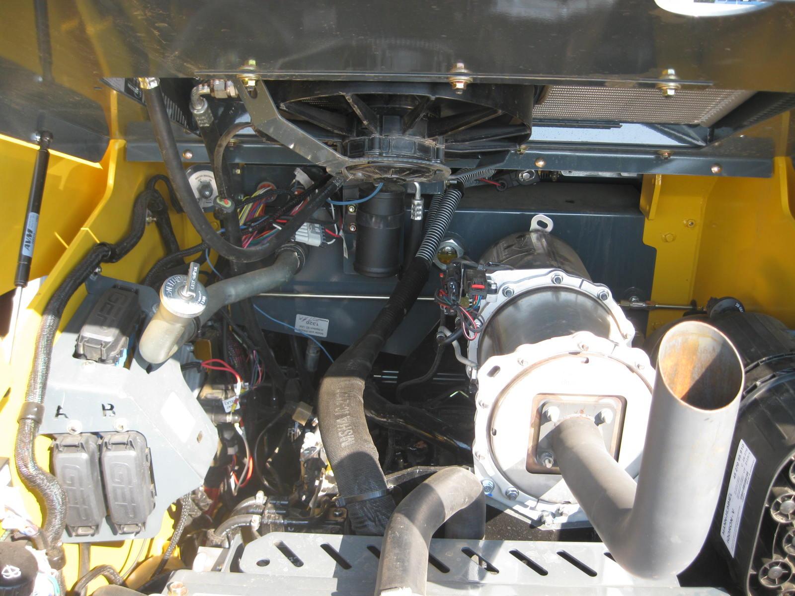
Inside the engine compartment, the loader has a sight gauge located at the back wall of the skid-steer loader engine compart ment (Figure17). Check the fluid level with the lift arm lowered and the attach ment bracket on the ground. Add hydraulic oil as required in the hydraulic oil fill tube. Oil should fil1 1/2 to 3/4 of the sight gauge, leaving a small amount of visible light at the top to ensure the tank is not over full. Refer to the Lubrication chart (page79). Replace the fill cap.
Changing Hydraulic Oil Filter
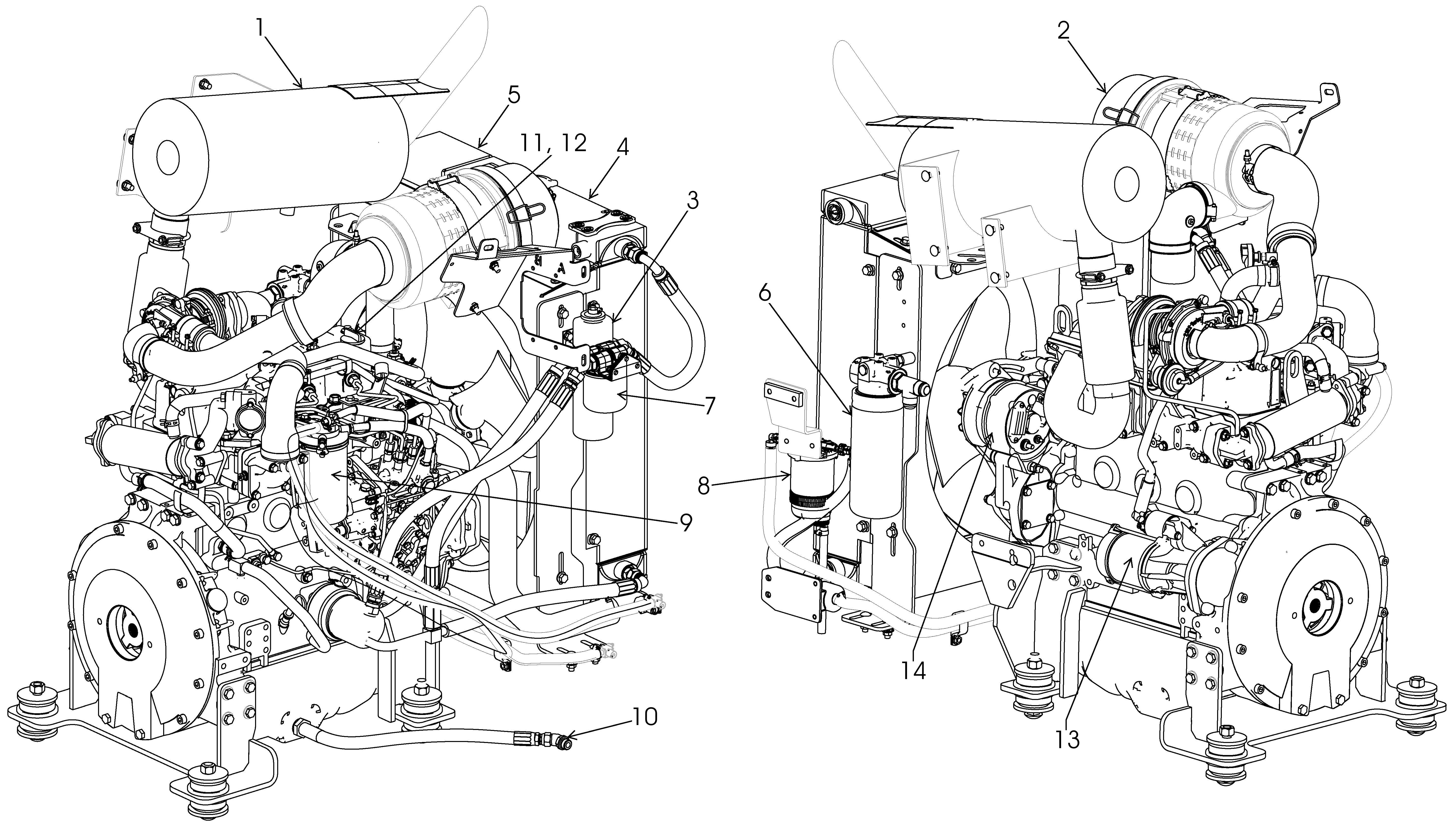
The hydraulic filter element is located to the right of the radiator/cooler, against the side of the chassis. To change the hydraulic filter element:
1.Park the loader on a level surface. Shut off the engine and remove the key.
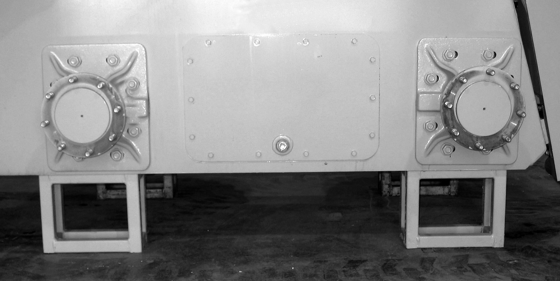
2.Open the reservoir drain plug located behind the right rear tire (Figure19).
3.Drain the oil to a level below the point where the filter attaches to the reservoir.
Note: Unbolt the water separator from the chassis for greater access to the hydraulic filter, if needed.
4.Replace the reservoir drain plug.
5.Clean any dirt/debris off the surface of the filter housing.
6.Spin off the old hydraulic filter element and spin on the new filter element.
7.Lubricate the seal on the new filter element with hydraulic oil before installing.
8.Refill the hydraulic oil reservoir with oil (if needed). Refer to the Lubrication chart (page79).
Changing Hydraulic Oil
The hydraulic oil must be replaced if it becomes contaminated, after major repairs and after 500 hours or one year of use.
1.Install a catch pan of sufficient capacity under the oil reservoir. See page79.
2.Remove the drain plug located behind the right rear tire. Allow the oil to drain.
3.Reinstall the drain plug.
4.Change the oil filter.
5.Refill the reservoir. Refer to the Lubrication topic (page79).
6.Start the engine and operate the hydraulic controls.
7.Stop the engine and check for leaks at the filter and reservoir drain plug.
8.Check the fluid level and add fluid, if needed.
Bucket Cutting Edge
The bucket cutting edge should be replaced when it is worn to within 1in. (25mm) of the bucket body.

Alternator/Fan Belt
Refer to the separate engine manual for setting proper belt tension. If the belt is worn, cracked or otherwise deteriorated, replace the belt following the procedure in the engine manual.
Wheel Nuts
Wheel nut torque must be checked before initial operation and every two hours thereafter until the wheel mounting hardware torque remains at 180ft.-lbs. (244N·m). When wheels are removed and reinstalled this procedure must be repeated.
Cooling System
Important: Check the cooling system daily to prevent overheating, loss of performance and engine damage. Drain, flush and refill coolant every year or 1,000 hours.
Checking Coolant Level
1.With the engine at operating temperature, open the engine cover. Looking at its plastic coolant recovery tank, check that the coolant tank fluid is half way up on the recovery tank, between full and low markings on the coolant tank (Figure20).
2.Allow the coolant to cool. Do not remove the fill tube cap when the coolant is hot. Serious burns may occur.
3.Add premixed coolant, 50% water and 50% ethylene glycol, to the tank if the coolant level is low.
Cleaning the Cooling System
Warning
Allow sufficient time for the oil radiator to cool before working on or near it. Parts get extremely hot during operation and can burn you.
The radiator assembly is mounted between the engine and the hinged rear grille. When operating correctly, air is blown through the openings between the fins by the engine fan. During operation dust and debris can build up on the engine side of the radiator and restrict air flow through the fins. To remove this restriction, use compressed air and direct the flow through the fins from the rear of the radiator toward the engine.
1.Lower the lift arm and stop the engine. Allow the machine to cool.
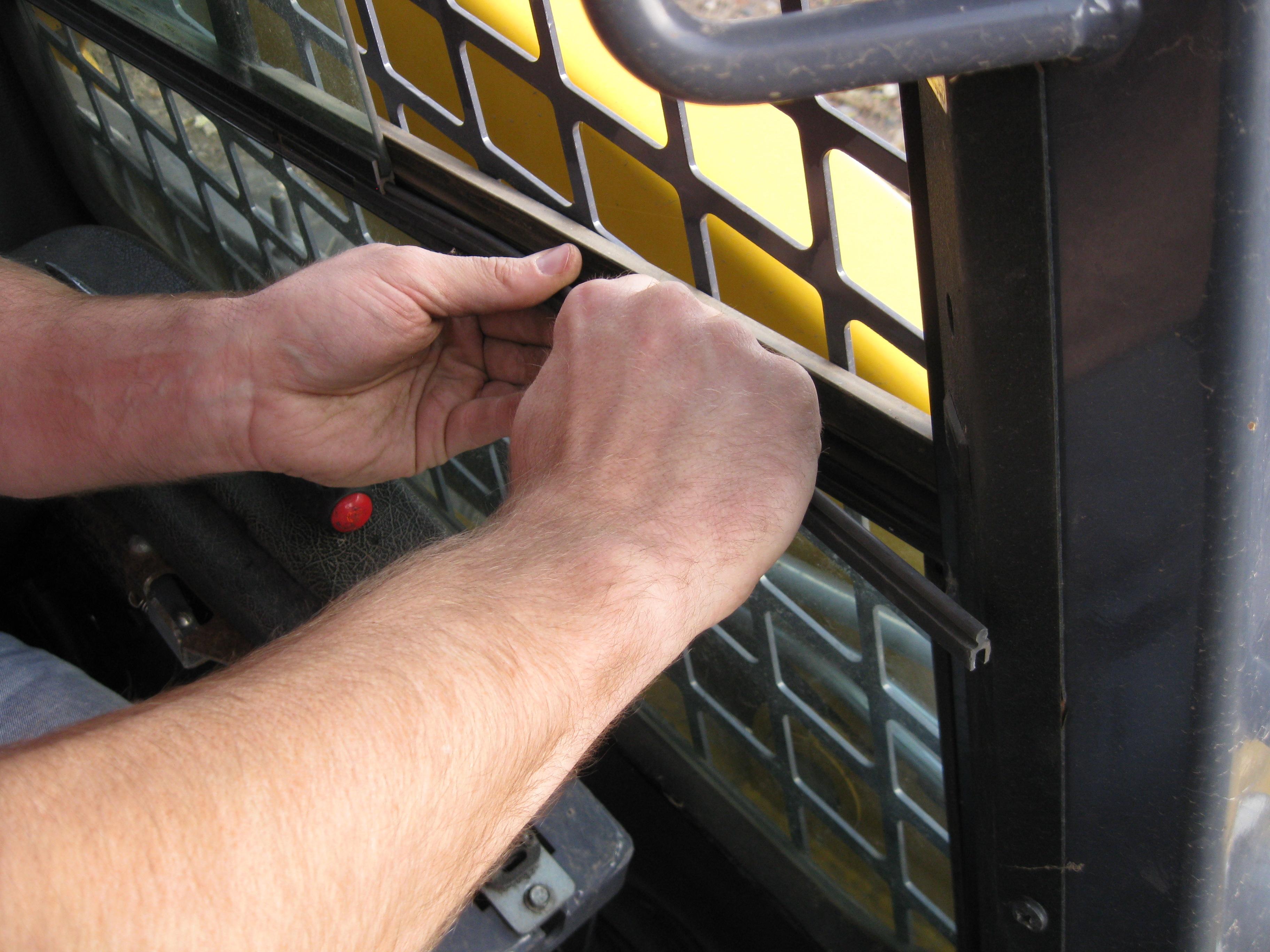
2.Raise the engine cover and open the rear grille (page76).
3.As necessary, clean the radiator and air cooler by blowing compressed air through the fins from the rear, toward the engine.
Draining/Flushing the Cooling System
1.Drain, flush and refill once every year or at 1,000 operating hours.
2.Lower the lift arm and stop the engine. Allow the machine to cool.
3.Raise the engine cover and open the rear grille (page76).
4.Remove the radiator cap on the coolant tank.
5.Open the drain cock on the radiator (Figure21) and drain the coolant into a suitable container.
Note: Coolant must be drained from the radiator and the engine.
6.Close the drain cock.
Note: Protect the cooling system by adding premixed 50% water and 50% ethylene glycol to the system.
7.Fill the radiator fully and the coolant tank to half full.
8.Reinstall the radiator cap and run the engine until it is at operating temperature.
9.Stop the engine and let it cool. Check the coolant level. Add more fluid, if necessary.
Inflating or servicing tires can be dangerous. When possible, trained personnel should service and mount tires. To avoid possible death or serious injury, follow the safety precautions below.
To keep tire wear even, rotate the tires from front to rear and rear to front.
It is important to keep the same size tire on each side of the loader to prevent excessive wear on tires, chains, or other damage. If different sizes are used, tires will be turning at different speeds, causing excessive wear.
Note: The tread bars of all tires should point the same direction.
BE SURE the rim is clean and free of rust.
Lubricate the tire beads and rim flanges with a soap solution. Do NOT use oil or grease.
Use a clip-on tire chuck with remote hose and gauge, allowing you to stand clear while inflating the tire.
NEVER inflate beyond 35 psi (240 kPa) to seat the beads. If the beads have not seated by the time the pressure reaches 35 psi (240 kPa), deflate the assembly, reposition the tire on the rim, lubricate both parts and re-inflate. Inflation pressure beyond 35 psi (240 kPa) with unseated beads may break the bead or rim with explosive force sufficient to cause death or serious injury.
After seating the beads, adjust the inflation pressure to the recommended operating pressure.
Do NOT weld, braze or otherwise attempt to repair and use a damaged rim.
Checking Tire Pressure
Correct tire pressure should be maintained to enhance operating stability and extend tire life. Refer to the chart below for proper inflation pressures.
Heater/Air Conditioner Filters
The optional heater and heater/air conditioner include two filters: fresh air intake and recirculation air.
Refer to the Replacement Parts topic (page74) for filter part numbers. Filters should be replaced as needed.
Fresh Air Intake Filter: Located directly behind the cover on the HVAC (heating, ventilating and air conditioning) housing mounted on the upper rear corner of the cab. Remove the threaded knobs on both sides of the cover to access the filter.
Recirculation Air Filters: Located behind the covers in the headliner directly above the rear window. The access, remove the screws on either side of the covers.
Important: Keeping the cab clean will reduce need for service and help ensure proper air conditioner and heater operation. Failure to do so can cause evaporator and heater core plugging, fan noise, vibration and failure.