5 minute read
Loader Raising Procedure

from Gehl V270 GEN2 V270 GEN2 (EU) V270 GEN2 X-Series V330 GEN2 V330 GEN2(EU) V330 GEN2 Operator's Manual
To raise the skid-steer loader so all four tires are off the ground, use the procedure below:
Warning
Do not rely on a jack or hoist to maintain the raised position without additional blocking and supports. Serious personal injury could result from improperly raising or blocking the loader.
1.To block the loader, obtain enough suitable blocks (solid wood, hard plastic or metal) so all of the tires are raised off the ground.
Figure2 Loader Properly Blocked (Tires and wheels removed to show blocks)
2.Using a jack or hoist capable of lifting the fully-equipped weight of the loader (with all attached options), lift the rear of the loader until the rear tires are off the ground.
3.Stack wooden, hard plastic or metal blocks under the flat part of the loader chassis. They should run parallel with, but not touch, the rear tires.
4.Slowly lower the loader until its weight rests on the blocks. If the tires still touch the ground, raise the loader again, add more blocks and lower again.
5.Repeat steps 2 through 4 for the front end. When the procedure is finished, all four tires are off the ground, so they could be removed.
Loader Lowering Procedure
When service or adjustment procedures are complete, the loader can be lowered from the raised position. To lower the loader onto its tires:
1.Using a jack or hoist, raise the front of the loader until its weight no longer rests on the front blocks.
2.Carefully remove the blocking under the front of the loader.
3.Slowly lower the loader until the front tires are resting on the ground.
4.Repeat steps 1 through 3 for the rear of the loader. When the procedure is finished, all four tires will be on the ground and the blocks removed from under the loader.
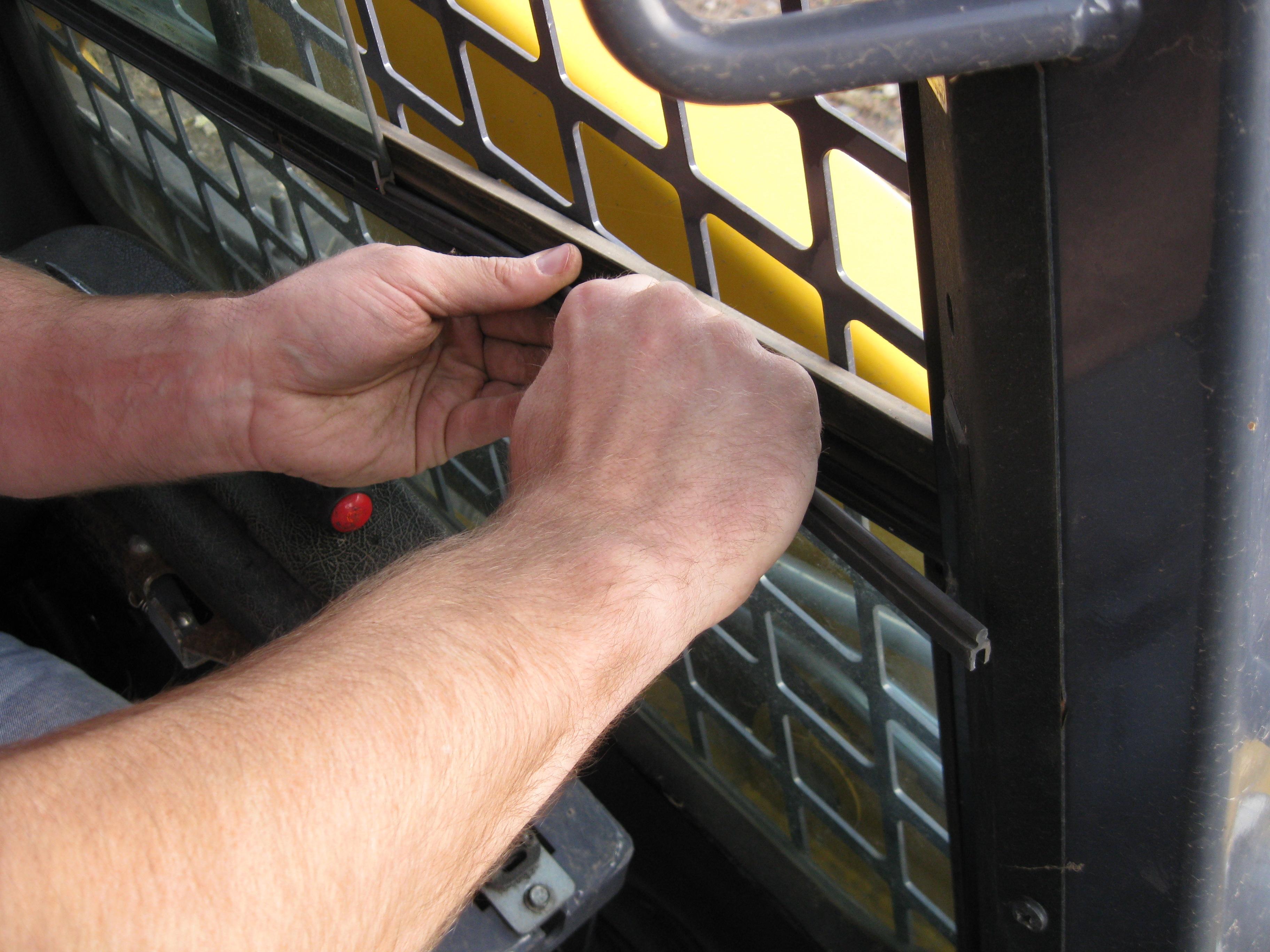
Engine Compartment Access
To open the engine compartment, lift the engine cover. Then pull the rear grille latch up and carefully swing open the rear grille. There is another rear grille latch near the top hinge pin of the grille to secure the grille in an open position.

Tilting Back the ROPS/FOPS
A manual lock mechanism is used as a gas spring lock to prevent the raised ROPS/ FOPS from lowering unexpectedly. The manual lock mechanism engages to lock the ROPS/FOPS in a tilted-back position.

To tilt back the ROPS/FOPS, remove two hex nuts on two anchor bolts at the front of the ROPS/FOPS. Tilt it back slowly, moving the control handles out of the way. Two gas-charged springs help tilt it back. A self-actuating lock mechanism will engage to lock when the ROPS/FOPS is in a rolled-back position. To lower the ROPS/ FOPS, return the lock mechanism to the unlocked position (flipper up). Lower the ROPS/FOPS slowly onto the chassis. Reinstall the anchor bolts, washers and locknuts. Refer to the Torque Specifications chart (page129) for torque information.
Warning
Never operate the loader with the ROPS/FOPS removed or tilted back. Be sure the lock mechanism is securely engaged when the ROPS/FOPS is tilted back. Be sure to reinstall the anchor bolts, washers and locknuts before resuming operation. Additionally, DO NOT raise or lower the lift arm with the ROPS/FOPS rolled back.
Adjustments
Control Handles
The control handles do not require routine adjustment. Refer to the Service Manual for the initial setup procedure.
Removing Foreign Material
The loader should be cleared daily of dirt and other foreign materials in the following areas:
•around the lift cylinders
•at the front of the loader
•on the hitch, especially around tilt cylinder
•around the hydraulic oil reservoir breather
•in the engine compartment
•in the operator’s compartment
Important: Build-up of foreign materials in these areas can interfere with the operation of the loader, cause component damage or become a fire hazard.
Lubrication
Listed below are the temperature ranges and types of lubricants for this machine. Refer to the separate engine manual for more information regarding engine lubricants, quantities and grades required.
Note: Refer to the specific service sections for detailed information on periodic checking and replenishing of lubricants.
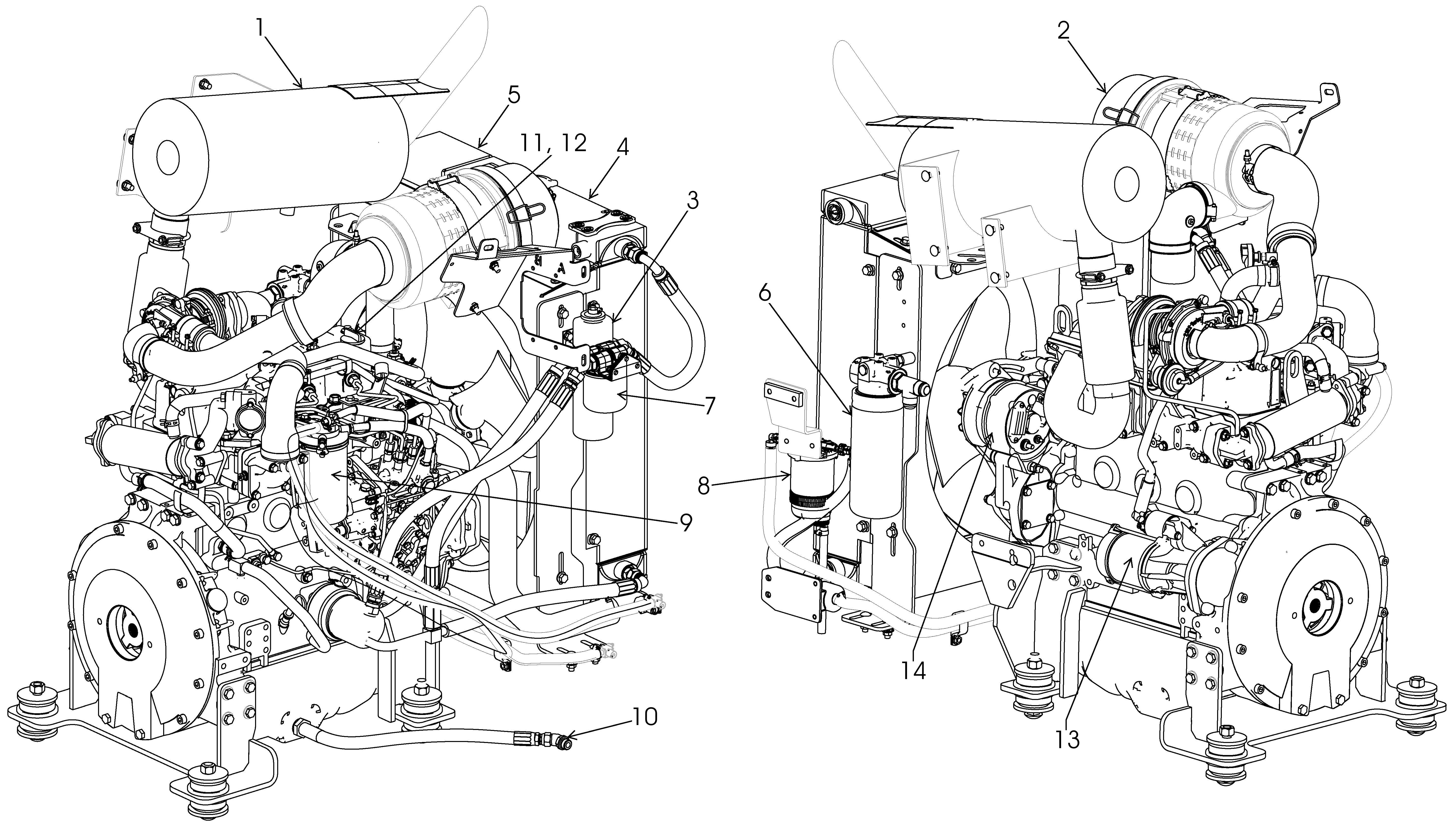
Refer to Figure6 for grease fitting locations. Wipe dirt from the fittings before greasing them to prevent contamination. Replace any missing or damaged fittings. To minimize dirt build-up, avoid excessive greasing.
Important: Always dispose of waste lubricating oils and hydraulic fluids according to local regulations or take to a recycling center for disposal. Do not pour onto the ground or down the drain.
System Lubricant

Hydraulic System Oil
Use Petro Canada HVI60, Mobil DTE 15M or equivalent, which contain anti-rust, anti-foam and anti-oxidation additives, and conforms to ISO VG46.
Entire System Capacity, V270: 15 U.S. gallons (56,7 L)
Entire System Capacity, V330: 15 U.S. gallons (56,7 L)
Bare Reservoir Capacity: 10.5 U.S. gal. (39,7) L
Use SAE grade 10W-30 motor oil.
Chaincase Oil
V270 Capacity (each side): 8.5 U.S. quarts (8 L)
V330 Capacity (each side): 8.5 U.S. quarts (8 L)
Grease Fittings Use lithium-based grease.
Engine oil type: 0W-40 Full Synthetic Oil
Engine Oil
API-CK-4 preferred
API-CJ-4 acceptable
V270 Capacity: 11.0 U.S. quarts (10,4 L)
V330 Capacity: 11.0 U.S. quarts (10,4 L)
Check Engine Oil Level (page88)
Check Hydraulic Oil Level (page97)
Grease Hitch, Hitch-related Cylinder Pivots and Latch Pins (page79)
Grease Lift Arm Pins (page79)
Check Oil Level in Chaincases (page81)
Change Engine Oil/Filter - DPF (page88)
Change Engine Oil/Filter - Non-DPF (page88)
Change Hydraulic Oil Filter (page97)
Change Hydraulic Oil (page98)
Change Chaincase Oil (page81)
Check & Drain Water Separator (page89)
Replace Filter in Water Separator (page89)
Perform the procedure at 1000 hours.
Chaincases
There is a chaincase on each side of the loader. Refer to the Maintenance Interval Chart (page115) for change intervals. Refer to the Lubrication chart (page80) for the type of lubricant.
Checking and Adding Oil
1.Park the loader on a level surface. Shut off the engine and remove the key.
2.Older Models: Remove the fill check plug (Figure7) from each chaincase cover. The oil level should be at the plug level or no more than 1/4 in. (6 mm) below the plug.
3.If the level is low, add fluid through the fill plug until the oil level reaches the check plug hole. Reinstall the plugs.
4.Newer Models: Remove the combination check/fill/drain check plug on one side at the front of the loader ( ). The oil level should be at the plug level or no more than 1/4 in. (6 mm) below the plug, Check the other side accordingly.
Draining Oil

1.Park the loader on a level surface, or on a sloping surface with the loader facing downhill and the tires blocked.
2.Newer Models: If loader is parked on a level surface, use a heavy-duty hydraulic jack between the rear tires to slightly tilt the loader upward to facilitate oil removal.

3.Remove the drain or combination check/ drain/fill plug on each chaincase (Figure8) and drain the oil into a suitable container.
4.Reinstall and tighten the drain or drain/fill plugs.
5.Refill the chaincases at the fill plugs per the procedure above.
Drive Chains
Drive chains are located in the chaincase on each side of the machine. Refer to the Maintenance Interval Chart (page115) for tension check interval.
Checking Chain Tension
1.Raise the loader following the Loader Raising Procedure (page75).
2.Rotate each tire by hand. The proper amount of chain defection should be 1/8 in. to 1 in. (3 to 25 mm) forward and rearward tire movement. If the chain defection is more than 1in. (25 mm) or less than 1/8 in. (3 mm) in either direction, the chains should be adjusted.
Adjusting Chain Tension
1.Raise the loader following the Loader Raising Procedure (page75).
2.Remove the tire from the axle to be adjusted.
3.Loosen (but DO NOT remove) the bolts holding the axle to the chaincase.
4. Front Chain Tension – To tighten the front chain, move the front axle assembly toward the front of the loader. To loosen the chain, move the front axle assembly toward the rear of the loader.
Rear Chain Tension – To tighten the rear chain, move the rear axle assembly rearward. To loosen the chain, move the rear axle assembly toward the front of the loader.
5.After proper tension is achieved, retighten the bolts.
Important: Be careful not to over-tighten the drive chains. Over-tightening will cause premature drive chain and axle sprocket wear.
6.Reinstall the tire.
7.Repeat steps 2 through 6 for any other axle requiring adjustment.
8.Lower the loader following the Loader Lowering Procedure (page76).