3 minute read
DPF Regen Flowcharts (DPF Models), cont.

from Gehl V270 GEN2 V270 GEN2 (EU) V270 GEN2 X-Series V330 GEN2 V330 GEN2(EU) V330 GEN2 Operator's Manual

If a Stationary Regen Mode is requested by the ENGINE— ECU
DPF REGEN ACKNOWLEDGE (Electronic Display)
DPF SWITCH
When these icons are ac ve, the E-ECU is reques ng a Sta onary Regen.
A Sta onary Regen Procedure is required within 10 hours.
Sta onary Regen
See Sta onary Regen Procedure for complete details.
DPF SWITCH Press and hold Sta onary Regen Request switch for three seconds.
What happens if a Sta onary Regen Procedure is not performed within 10 hours?
Keeping the DPF switch in the CANCEL posi on for more than 10 hours OR
Keeping the DPF switch in the center AUTO posi on for more than 10 hours automa cally transfers the E-ECU to Backup mode.
These icons will appear on the Electronic display during the Sta onary Regen mode.

Backup Mode (Limp Mode)
Camera Observation System
A camera observation system is optionally available on all models. The camera observation system utilizes a rear-facing camera mounted within the rear door of the machine to provide full visibility to the region behind the machine of which portions of that region may otherwise be masked by the machine’s structure.
The camera system is configured to turn on automatically when the machine’s ignition switch is moved to the “ON” position. The camera image is displayed on the monitor which is centered above the front door opening of the operator’s compartment.
The vertical viewing angle of the monitor is adjustable by loosening the knobs positioned on either side of the monitor. Prior to operating the machine the operator should check the monitor to verify that the monitor is positioned at the optimum viewing angle for them.
As an integral safety feature of the machine it is important for the operator to verify that the camera system is operating properly prior to moving the machine. A camera system that is operating properly will display a sharp image that is free of any obstructions when the key is switched on. The displayed image should be centered on the area directly behind the machine. If the displayed image does not meet this criteria the following system checks can be made:
While the system is configured to power up automatically upon key on, depress the system power button at the display to see if the system powers up.
Verify that the electrical connections to the monitor and camera are intact. This includes checking the A/V cable connection into the rear of the monitor and the camera connection to the camera extension cable located in the engine compartment in close proximity to the rear door hinges.
Roll back the ROPS\FOPS and check the camera system harness connections forward of the engine flywheel housing. The connection of the camera system power harness to the accessory power connections in the chassis harness are located in this region. Verify that these connections are intact.
Locate the fuse holder in the camera system power harness near the cable’s interface with the chassis harness. Verify that the two Amp fuse within is intact and fully inserted into the fuse holder terminals. Also, verify that the 20A chassis accessory fuse in the uppermost power distribution module is functional.
If the monitor displays a picture but that picture is not bright and clear, verify that the camera lens is clean and that the camera is properly aligned with the aperture in the rear door. The mounting brackets allow for left/right, up/down, and fore/aft adjustment. When making adjustments, ensure that the resulting pictures displayed on the monitor squarely shows the area behind the loader.
Additional troubleshooting measures are detailed in the camera observation system manual for instructions on how to correct any issues.
If the camera system is not able to be made functional after these initial checks, contact your dealer for service. A camera system that is unable to provide a clear image of the rear of the machine should be considered disabled and the machine should not be operated until the camera is made to function properly again.
Back-Up Alarm
A back-up alarm system is optionally available which serves to warn people working in the area around the machine of the machine’s rearward movement. The back-up alarm is installed within the engine compartment on the inside surface of the rear door. The alarm emits a tone whenever the machine begins to move in the rearward direction.

14-Pin Auxiliary Connector
A 14-pin auxiliary connector is optionally available on all models. It is located at the knee joint of the lift arm (Figure10) and is intended for attachments equipped with 14-pin compliant connections using direct 12 volt actuation control.
NOTE: Contact your dealer for information about approved 14-pin-equipped attachments.
Switch / Pin Assignments
Refer to Figure11 and Figure12 and the following table (Table1) for details about the 14-pin control switches and the associated pins in the 14-pin connector.
Figure12 Switch-to-Pin Assignments
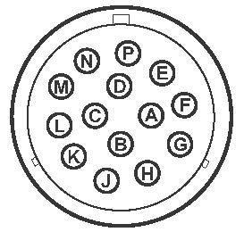
Table 1: 14-Pin Switch and Pin Assignments
Switches 1, 2, and 3 have a combined total capacity of 15A.
Switches 1, 2, 3 and 4 have a combined total capacity of 20A.
NOTE: Depending upon the attachment, an adapter harness may be necessary. Refer to the documentation supplied with the attachment, or contact your dealer.