9 minute read
Transporting/Towing the Loader

from Gehl V270 GEN2 V270 GEN2 (EU) V270 GEN2 X-Series V330 GEN2 V330 GEN2(EU) V330 GEN2 Operator's Manual

Park the truck or trailer on a level surface. Be sure the vehicle and its ramps have the weight capacity to support the loader. Make sure the vehicle surface and its ramps are clear of debris and slippery material that may reduce traction. Move the loader on and off the vehicle ramp slowly and carefully. Failure to follow these instructions could result in an overturn accident. Towing the loader is not recommended as a means of transportation.
Observe all local regulations governing the loading and transporting of equipment (Reference: U.S. Federal Motor Carrier Safety Regulations, Section 392). Ensure that the hauling vehicle meets all safety requirements before loading the skid-steer loader. Use the tie down/retrieval points in situations where lifting the loader is not possible and the overall distance by which the loader is to be moved is less than 100 feet (30.5 m) at 6 mph (10 km/hr) or less. The optional brake release package (page50) facilitates loader retrieval in such situations. When transporting a loader:
1.Block the front and rear of the hauling vehicle’s tires.
2.If the loader has an attachment, lift it slightly off the ground.
3.Back the loader slowly and carefully up the ramp onto the vehicle.
4.Lower the loader attachment to the vehicle deck, turn off the engine and remove the key.
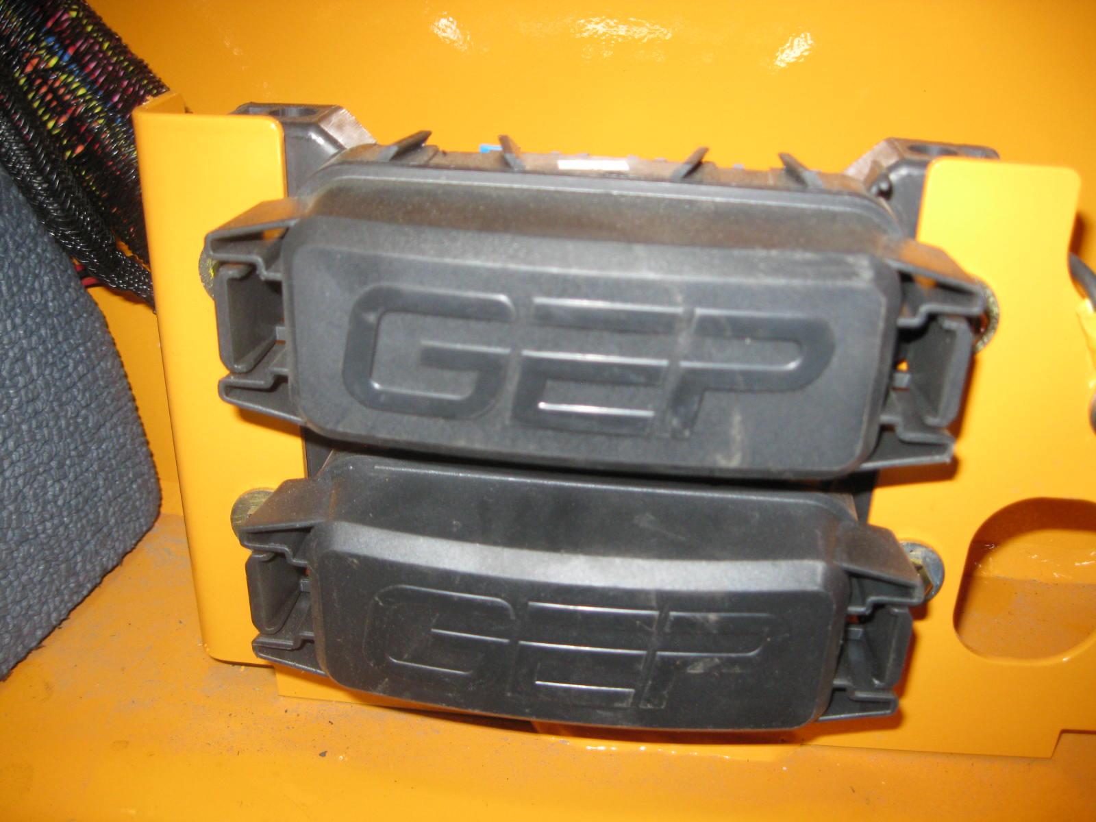
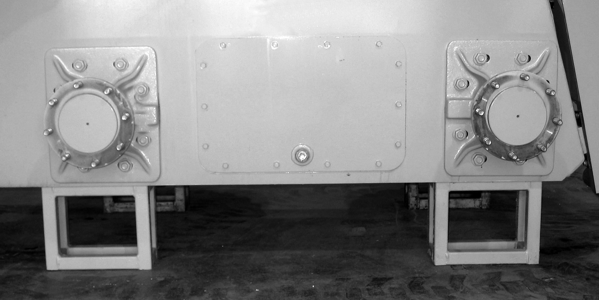
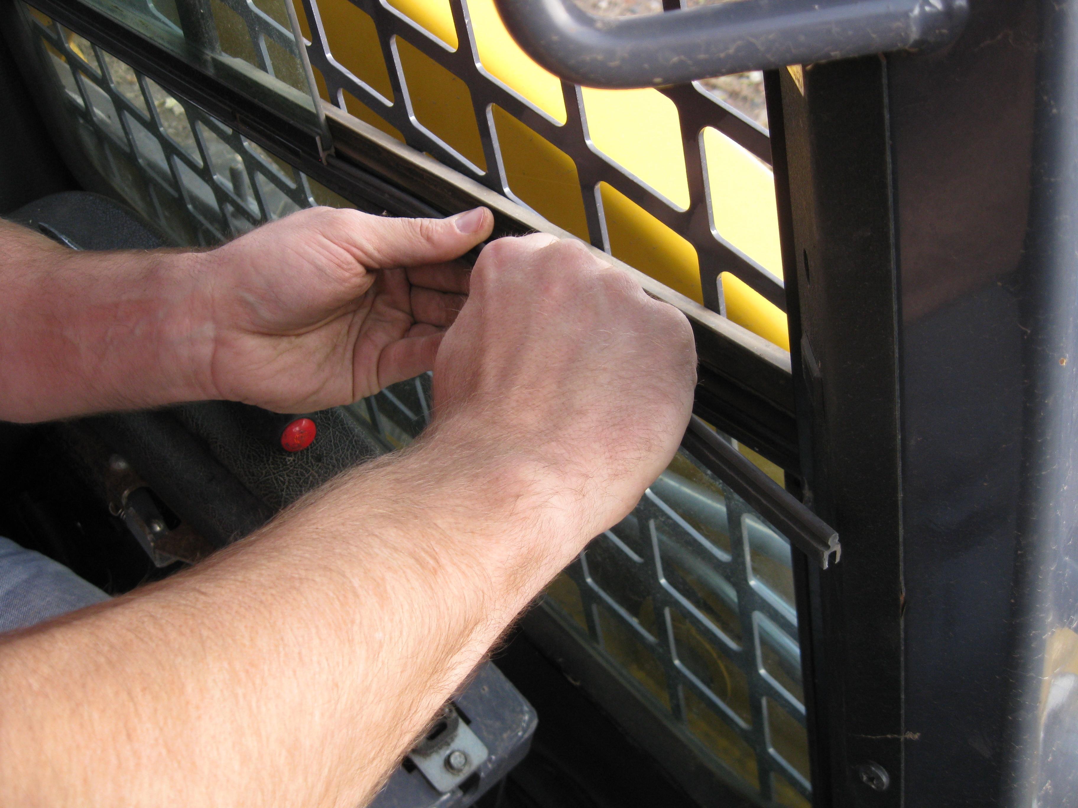
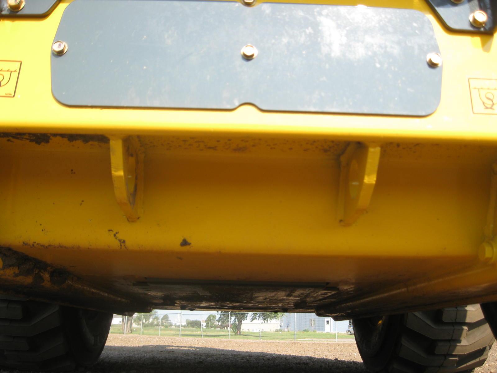
5.Fasten the loader to the hauling vehicle at the points indicated by the tiedown decals (Figure7 and Figure8).
6.Measure the clearance height of the loader and hauling vehicle. Post the clearance height in the cab of the vehicle.
When towing a loader:
1.Connect the towline to both tie down/ retrieval points at the front or the rear of the loader. Use of only a single retrieval point or connecting the towline to any point on the loader other than the designated retrieval locations could result in loader damage.
2.The towline strength is at least 1.5 times the gross weight of the loader. The towline length is such that the maximum towing angle does not exceed 20°.
Lifting the Loader
The loader can be lifted using a single-point or four-point lift kit, which are available from your Gehl dealer.
Warning
•Before lifting, check the lift kit for proper installation.
•Never allow riders in the operator’s compartment while the loader is lifted.
•Keep everyone a safe distance away from the loader while it is lifted.
•Loader may only be lifted with an empty bucket or empty pallet forks, or with no attachment. Never lift the loader with attachments other than those stated.
Lift equipment used and its installation is the responsibility of the party conducting the lift. All rigging MUST comply with applicable regulations and guidelines.
1.Using suitable lift equipment, hook into the lift eyes. Adjust the length of the slings or chains to lift the loader level.
Note: The loader may be slightly off level (10 degrees max.) when lifted.
2.Center the hoist over the ROPS/FOPS. To prevent shock loading of the equipment and excessive swinging, slowly lift the loader off the ground. Perform all movements slowly and gradually. As needed, use a tag line to help position the loader and keep it from swinging.
DPF (Diesel Particulate Filter) Regeneration (DPF Models)
The Gehl V270 and V330 GEN:2 Tier 4 series skid-steer loaders utilize a DPF (diesel particu late filter) regen system on the engine to meet Tier 4/Stage 3B emission requirements. The information center electronic display will auto matically alert the user when a regen of the engine is required.
All DPF regen functions are controlled by the EECU (Engine-Electronic Control Unit) and the DPF switch.
The DPF switch operates in this manner.
1.Auto Regen: The neutral center AUTO position of the switch allows the E-ECU to transparently perform low-level (self and assist) DPF regen, without operator input.
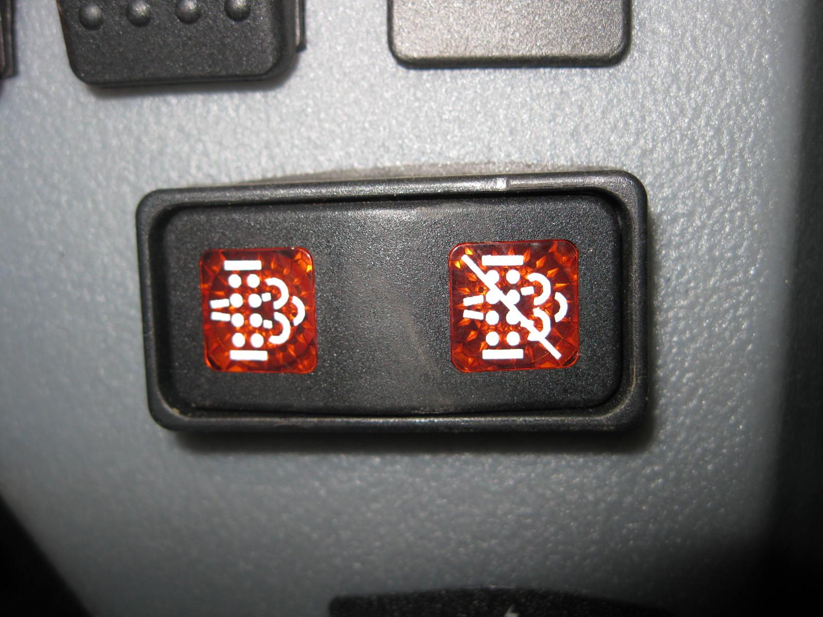
2.Stationary Regen Start: The left side of the switch is a momentary switch used for starting a stationary regen.
3.Stationary Regen Request Lamp: The lamp prompts the operator to implement a stationary regen. It is used for notifying the operator that the stationary regen request has been made by the E-ECU. This light will flash requesting stationary regen. After the switch is pressed for three seconds or more the light will change state indicating the engine is in stationary regen mode.
4.Inhibit Regen (Delay): The right side of the toggle switch is used for delaying Reset regen. The purpose of this feature is to prevent unexpected hot exhaust in situations that the heat could be dangerous. This will INCREASE the possibility of requiring a stationary regen. If the switch is placed in this position the E-ECU will not perform reset regen and soot may build up in the soot filter. This build up may also lead to a 50% reduction in engine power and a required soot filter replacement.
5.Inhibit Regen (Delay) Lamp: The lamp is used for notifying the operator that the inhibit switch has been activated which will delay reset regen.
Important: During regen, there may be a change in sound due to the intake throttle and the EGR (Exhaust Gas Recirculation) valve opening changes, but normal regen should otherwise be transparent to the operator. The exhaust may also smell different from non-DPF equipped diesel engines.
There is a possibility of carbon monoxide poisoning if the regen occurs in enclosed spaces. Be sure to allow for an outside air source or park the loader outside during a regen.
During regeneration there will be high exhaust gas temperatures, even at low load. Be sure to stay clear of the DPF during a regen.
The machine should not be used or moved when a stationary regen is being performed. If the machine must be moved, releasing the parking brake, moving the throttle, or cycling the key will interrupt the stationary regen and allow operation of the machine.
Before executing a regen procedure, it is recommended that operators become familiar with some terms and definitions related to a DPF (Diesel Particulate Filter) regen.
Regen Terms and Definitions
DPF: Diesel Particulate Filter
SF: Soot Filter
Regen: Short for regeneration.
Regeneration: The process of raising the exhaust temperature to burn off the particulate matter from the DPF.
PM: Particulate matter in the DPF
Hours: Refers to the engine run-time hours.
E-ECU: Refers to the Engine-ECU Control Unit.
DTC: Diagnostic Trouble Codes
EGT: Exhaust Gas Temperature
Passive regen and assist regen: These automatic DPF regen modes occur without any operator input and without affecting machine operation.
Reset regen: This DPF regen mode intentionally increases exhaust gas temps to remove PM. Review all precautions regarding high exhaust temps. The operator can continue to operate all skid-steer loader functions. Reset regen is initiated by the E-ECU, but the operator has the option to delay this function. A reset-regen is a 100 hour recurring event unless other factors, such as engine load and effective PM levels determine otherwise.
Note: The operator can improve the effectiveness of the reset regen by operating the skid-steer loader at a middle to high throttle position during the reset regen.
Stationary regen: This DPF regen mode is ONLY used if the engine is operated without sufficient load and/or rpm for normal regen to occur. It includes engine speed control to further facilitate DPF regen. If the DPF regen-required lamps illuminate, the operator should move the skid-steer loader to a safe place without flammable material nearby before starting the stationary regen. For operation and other details, refer to the flow chart and stationary regen operating procedures. If the E-ECU requests a stationary regen, the engine will also automatically de-rate 15%. This 15% cannot be by-passed. If a stationary regen is not performed within 2 hours the engine will de-rate to 50%. This power reduction cannot be by-passed. If the machine is operated for a total of 10 hours after the Stationary Regen has been requested and not been performed, engine will go into Backup Mode. The machine cannot be operated while the stationary regen is being performed. This procedure will take approximately 25 to 30 minutes. Consult this manual for the procedure.
Backup Mode: In the backup mode, the engine has reduced revolutions per minute (RPM) and power. A number of DTC’s are to be expected. Refer to the DTC listing (page89) for a complete summary and troubleshooting techniques. To release the engine from the backup mode, the service tool (Smart Assist) is required along with a soot filter replacement. Contact your dealer for full details.
Ash Cleaning Mode: To be determined.
Engine Stop
The engine stop icon is used to notify the operator that the engine is in “backup” or “limp” mode. See the backup mode description on page62 for more details.

DPF (Diesel Particulate Filter) Service (DPF Models)
The DPF service icon is used to notify the operator that the engine is in an emergency condition where ash cleaning is required. See the ash cleaning mode description on page62 for more details.
Elevated EGT (Exhaust Gas Temperature) (DPF Models)
The EGT icon is used to notify the operator of high exhaust temperatures during an active reset/stationary regen.
Parking Brake (DPF Models)
The parking brake icon is used to remind the operator that the parking brake switch must be engaged prior to a stationary regen.
DPF Regeneration Acknowledgement (DPF Models)
The DPF regen acknowledgement icon is used to notify the operator that the E-ECU has received the stationary regen request. It is also used to prompt the operator to start a stationary regen request or to allow a reset regen.
Aftertreatment Error
Engine Emission System Failure. Indicates an error or fault with emission critical components.
NOTE: Engine derate will occur if error/fault not corrected.
Stationary Regeneration Safety (DPF Models)
Before beginning a stationary regen operation there are several safety precautions to be aware of:
Do not do a stationary regen in a poorly ventilated location. There is the danger of carbon monoxide poisoning.
Be sure that there are no flammables near the exhaust pipes to avoid fires.
Do not touch the exhaust pipes during stationary regen to avoid injury. Be sure there are no people close to the exhaust pipes.
After stationary regen starts, white smoke may be discharged from the exhaust pipe. This is not a fault, but steam discharged when the exhaust temperature is low. As the exhaust temperature increases, the white smoke should disappear.
Stationary will not operate if there are any DTC codes in the system. The condition which caused the DTC must be fixed.
The exhaust gas has a different odor from that of a conventional diesel engine. This is not a fault. The different odor is generated because the exhaust gas is purified by the catalyst integrated in the DPF.
Other Stationary Regeneration Topics (DPF Models)
Besides the safety concerns listed above, the operator must also be aware of these additional stationary regen topics:
Extended duration of engine idling will rapidly increase soot levels in the DPF, requiring more frequent regen operations.
It is not a good practice to keep the DPF switch depressed in the INHIBIT position for extended periods of time, as this could reduce the standby-time allowed prior to some of the regen modes.
It is advised to not perform any additional machine functions during the stationary regen.
The operator does not have to be in the operator’s seat during the stationary or reset regen modes.
Inadvertent pressing of the DPF regen switch does not harm the DPF system, since the DPF will not execute a regen request until all the requirements in the operating procedures are met.
The stationary regen procedure consumes approximately 1 gal. (3,8 L) of diesel fuel.
Stationary Regeneration Procedure (DPF Models)
Take the following steps when performing a stationary regen. Refer to the DPF regen flowcharts (page67) for a further understanding of this procedure.
1.Move to a safe location that is well-ventilated.
2.Ensure there are no active DTC codes, DTC codes will prohibit a regen.
3.Set the acceleration of the engine to its lowest position and run the engine at idle speed. Ensure the engine’s coolant temperature is above 140° F (60° C).
4.Engage the parking brake.
5.When the DPF regen request switch is pressed:
Operator Initiated: Press and hold for 10 seconds, release, then hold for an additional three seconds and the stationary regen starts. The engine speed will gradually increase to a high idle speed.
E-ECU Initiated: Press and hold for three seconds and the stationary regen starts. The engine speed will gradually increase to a high idle speed.
6.The stationary regen procedure takes approximately 25 to 30 minutes to perform.
7.When the above time has passed, the engine speed gradually decreases to the low idle speed and the DPF regen acknowledgement lamp and the EGT lamp turn off. Stationary regen is completed.
Note: When stationary regen starts, the DPF regen-required lamp turns off, the DPF acknowledge lamp briefly appears and the EGT lamp illuminates.
Stationary Regeneration Abort Procedure (DPF Models)
To abort a stationary regen, perform any one of the following steps.
1.Set the DPF switch to its inhibit/cancel state.
2.Command the accelerator to a position above its lowest position.
3.Turn the manual parking brake switch to its OFF position.
4.Turn the keyswitch to the OFF position.
Note: Depending upon the PM levels and which switch was used to abort the stationary regen, the E-ECU will either go back to normal operation or stationary regen standby mode.
Note: Interrupting a reset or stationary regen will require a full reset or stationary regen process in the future. The E-ECU does not command partial reset or stationary regens.