31 minute read
Instrument Panels

from Gehl V270 GEN2 V270 GEN2 (EU) V270 GEN2 X-Series V330 GEN2 V330 GEN2(EU) V330 GEN2 Operator's Manual

Left Panel
1. Indicator and Warning Lamp Display –See page29.
2. Rotating Beacon/Strobe Switch (optional) –Controls the warning lamp (strobe or beacon).
3. Hazard/Flasher Switch (optional) – Controls hazard/flasher.
4. High/Low Beam Switch (optional) – Controls road head lights between main/upper beams and dimmed/lower beams. Switch does not turn lights on or off.
5. Turn Signal Switch (optional) – Used to turn on turn indicator lights. Directional indicator lights are the same lights as the flashers. The flashers will override the turn signals.
6. High-Flow Auxiliary Switch (optional) –Controls the direction of hydraulic oil flow. Push the right side of the rocker switch for forward flow, or the left side for reverse flow. To disengage, push and release either side of the switch, or raise the restraint bar. Turning off the machine and restarting the engine will also reset the high-flow to neutral.
7. Light Switch – Master control of the lights. Push the right side of the rocker switch to activate front and rear lights, or to the left side for deactivation of the front and rear lights. It also provides power to a machine equipped with flashers.
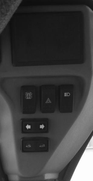
8. Light Switch – Controls all the lights on the loader. Push the rocker switch to the middle detent for front work lights and rear position lights. Push the rocker switch fully to the right for front work lights and rear work lights operation.
9. Self-Leveling Cancel (optional) – Press the top of the switch to deactivate self-leveling. Press the bottom of the switch to restore the self-leveling function.
Right Panel
1. Information Center Electronic Dis play – See page31.
2. Parking Brake Switch – Used to manu ally apply the parking brake. Lights when the parking brake is applied.
3.Front Wiper/Washer (optional)
4.Rear Wiper/Washer (optional)
5.DPF (Diesel Particulate Filter) Regen eration Switch – The DPF switch oper ates in this manner:
This is a three position switch. This switch should be placed in the neutral center AUTO position during normal operation. This will allow Auto Regen.
By placing the switch in the neutral position, this allows the E-ECU to transparently per form low-level (self and assist) DPF regen as required, without operator input.
The Right position puts the E-ECU into hibit mode, which will cancel and/or delay Reset DPF regen. This can be used to pre vent unexpected hot exhaust in situations that the heat could be dangerous. This will INCREASE the possibility of requiring a stationary regen. The light will illuminate when the switch is in this position.
The Left position is a momentary switch which can start a stationary regen when held in the on position for three seconds or more.
The Left light is used for notifying the oper ator that the E-ECU has requested a sta tionary regen and/or regen has been activated. The light will flash when a stationary regen is requested by the E-ECU and will become steady after the engine has been placed in the stationary regen mode.
Important: It is important to remember the switch should be in the neutral center position for normal operation.
6. Keyswitch – In a clockwise rotation, the positions are:
• OFF Position – With the key vertical, power from the battery is disconnected from the controls and instrument panel electrical circuits. This is the only position from which the key can be inserted or removed.
• ON (or RUN) Position – With the key turned one position clockwise from vertical, power from the battery is supplied to all control and instrument panel circuits.
• START Position – With the key turned fully clockwise, the electric starter engages, to start the engine. Release the key to RUN position after the engine starts.
Note: The engine cannot be started unless the operator is sitting in the seat and the restraint bar is lowered.
7. Power-A-Tach® System Switch – A three-position momentary rocker switch is used to actuate the Power-A-Tach System. Press the top of the switch to retract (release) the hitch pins; press the bottom of the switch to extend (engage) the hitch pins and activate the warming circuit. Set the switch to the neutral position (middle) to turn off the warming circuit (see page29).
8. Engine Speed Control – Controls the engine speed. Move the control clockwise to increase and counter-clockwise to decrease the engine speed.
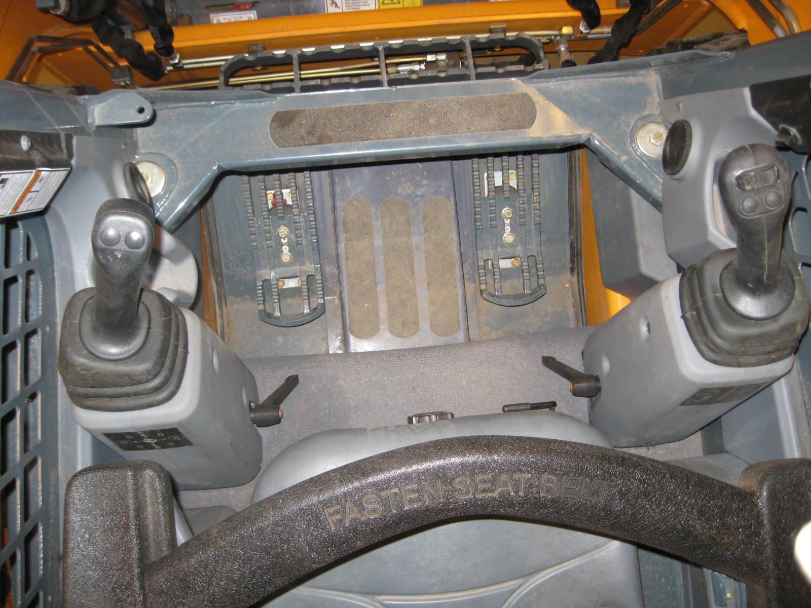
Joystick Controls
The loader may be equipped with dual joystick controls, (Figure14). The left control grip controls the drive, and the right control grip controls the lift/tilt.

Drive Controls
Forward, reverse, speed and turning maneuvers are accomplished by movement of the left control grip. To go forward, push the drive control forward; for reverse, pull the control rearward. To turn right, push the control right; to turn left, push the control left. To go forward and left, move the control forward and left. To go forward and right, move the control forward and right. To move back and left, move the control back and to the right. To move back and right, move the control back and to the left.
Be sure the controls are in neutral before starting the engine. Operate the controls gradually and smoothly. Excessive speed and quick control movements without regard for conditions and circumstances are hazardous and could cause an accident.
Moving the control grip farther from neutral increases the speed steadily to the maximum travel speed. Tractive effort decreases as speed increases. For maximum tractive effort, move the control grip only slightly away from the neutral position. The engine may stall if the control is moved too far forward when loading the bucket.
Lift/Tilt Control
Moving the lift arm and tilting the attachment are accomplished by movement of the right control grip. To raise the lift arm, pull the control straight rearward; to lower the lift arm, push the control straight forward. To tilt the attachment forward and downward, move the control to the right; to tilt the attachment up and back, move the control to the left.
Note: The speed of the lift/tilt motion is directly proportional to the amount of control grip movement and engine speed.
To place the lift arm into the “float” position, push and hold the left button on the right control grip. This mode allows the lowered lift arm to follow the ground contour while traveling over changing ground conditions. An indicator lamp in the indicator and warning lamp display will blink when float is activated.
Never push the float control button with the attachment raised, because this will cause the lift arm to lower very rapidly.
Releasing the float button will cancel the float mode if the button was pressed less than five seconds. If the float mode button is pressed longer than five seconds, the float feature will remain on and the float indicator lamp will remain lit until the button is pressed again or the machine is turned off.
Dual Hand Controls
The loader may be equipped with dual hand controls, (Figure15). The left control grip controls the left side drive and the lift. The right control grip controls the right side drive and the tilt.
Drive Controls
Forward, reverse, speed and turning maneuvers are accomplished by pushing and pulling the control grips. To go forward, push both control grips forward; for reverse, pull both control grips rearward. For turning, move one control grip farther forward or rearward than the other control grip. Turn direction is determined by which control grip is moved farther forward. To turn left, move the right control grip farther forward than the left control grip; to turn right, move the left control grip farther forward than the right control grip. For sharp turns, move the control grips in opposite directions.
Be sure the controls are in neutral before starting the engine. Operate the controls gradually and smoothly. Excessive speed and quick control movements without regard for conditions and circumstances are hazardous and could cause an accident.
Moving the control grips farther from neutral increases the speed steadily to the maximum travel speed. Tractive effort decreases as speed increases. To get maximum tractive effort, move the control grips only slightly away from the neutral position. The engine may stall if the control grips are moved too far forward when loading the bucket.
Lift/Tilt Control
Moving the lift arm and tilting the attachment are accomplished by rotating the control grips. To raise the lift arm, rotate the left control grip outward (to the left); to lower the lift arm, rotate the left control grip inward (to the right). To tilt the attachment forward and downward, rotate the right control grip; to tilt the attachment up and back, rotate the right control grip inward.
Note: The speed of the lift/tilt motion is directly proportional to the amount of control grip movement and engine speed.
To place the lift arm into the “float” position, push and hold the left button on the right control grip. This mode allows the lowered lift arm to follow the ground contour while traveling over changing ground conditions. An indicator lamp in the indicator and warning lamp display will blink when float is activated.
Never push the float control button with the attachment raised, because this will cause the lift arm to lower very rapidly.
Releasing the float button will cancel the float mode if the button was pressed less than five seconds. If the float mode button is pressed longer than five seconds, the float feature will remain on and the float indicator lamp will remain lit until the button is pressed again or the machine is turned off.
Hand/Foot Controls
The loader may be equipped with hand/foot controls (Figure16). The control grips control the drive and the foot pedals control the lift/tilt.
Drive Controls
Forward, reverse, speed and turning maneuvers are accomplished by movement of the control grips. To go forward, push both control grips forward; for reverse, pull both control grips rearward. For turning, move one control grip farther forward or rearward than the other control grip. Turn direction is determined by which control grip is moved farther forward. To turn left, move the right control grip farther forward than the left control grip; to turn right, move the left control grip farther forward than the right control grip. For sharp turns, move the control grips in opposite directions.
Be sure the controls are in neutral before starting the engine. Operate the controls gradually and smoothly. Excessive speed and quick control movements without regard for conditions and circumstances are hazardous and could cause an accident.
Moving the control grips farther from neutral increases the speed steadily to the maximum travel speed. Tractive effort decreases as speed increases. For maximum tractive effort, move the control grips only slightly away from the neutral positions. The engine will stall if the control grips are moved too far forward when loading the bucket.
Lift/Tilt Controls
Moving the lift arm and tilting the attachment are accomplished by movement of the foot pedals. The left pedal raises and lowers the lift arm; the right pedal tilts the attachment. To raise the lift arm, push down on the back of the left pedal with your left heel; to lower the lift arm, push down on the front of the left pedal with the toes of your left foot. To tilt the attachment forward and down, push down on the front of the right pedal with the toes of your right foot; to tilt the attachment up and back, push down on the back of the right pedal with your right heel.
Note: The speed of the lift/tilt motion is directly proportional to the amount of pedal movement and engine speed.
To place the lift arm into the “float” position, push and hold the left button on the right control grip. This mode allows the lowered lift arm to follow the ground contour while traveling over changing ground conditions. An indicator lamp in the indicator and warning lamp display will blink when float is activated.
Warning
Never push the float control button with the attachment raised, because this will cause the lift arm to lower very rapidly.
Releasing the float button will cancel the float mode if the button was pressed less than five seconds. If the float mode button is pressed longer than five seconds, the float feature will remain on and the float indicator lamp will remain lit until the button is pressed again or the machine is turned off.
T-Bar Controls
The loader may be equipped with T-bar controls (Figure17). The left T-bar controls the drive, and the right T-bar controls the lift/ tilt.

Drive Controls
Forward, reverse, speed and turning maneuvers are accomplished by movement of the left T-bar. To go forward, push the control forward; for reverse, pull the control rearward. To turn right, turn the control clockwise; to turn left, turn the control counterclockwise. For gradual turns, move the T-bar slightly forward or rearward. For sharp turns, turn the control clockwise or counterclockwise.
Moving the T-bar farther from neutral increase the speed steadily to the maximum travel speed. Tractive effort decreases as speed increases. To get maximum tractive effort, move the T-bar only slightly away from the neutral position. The engine will stall if the control is moved too far forward when loading the bucket.
Be sure the controls are in neutral before starting the engine. Operate the controls gradually and smoothly. Excessive speed and quick control movements without regard for conditions and circumstances are hazardous and could cause an accident.
Lift/Tilt Control
Moving the lift arm and tilting the attachment are accomplished by movement of the right T-bar. To raise the lift arm, pull the control straight rearward; to lower the lift arm, push the control straight forward. To tilt the attachment forward and downward, twist the control clockwise; to tilt the attachment up and back, twist the control counterclockwise.
Note: The speed of the lift/tilt motion is directly proportional to the amount of Tbar movement and engine speed.
To place the lift arm into the “float” position, push the right T-bar fully forward to detent. This mode allows the lowered lift arm to follow the ground contour while traveling over changing ground conditions. An indicator lamp in the indicator and warning lamp display will blink when float is activated.

Never push the right control handle fully forward to detent the float control with the attachment raised, because this will cause the lift arm to lower very rapidly.
Auxiliary Hydraulic System
Auxiliary hydraulics are used with attachments that have a mechanism requiring hydraulic power.
Note: When ignition power is interrupted, auxiliary hydraulic function (both standard and high-flow) are reset to OFF.
Standard-Flow Auxiliary Hydraulic Control
Loaders are equipped with a standard-flow auxiliary hydraulic system with flatface couplers. The couplers are located on top or inside of the lift arm on the left side.
Loaders equipped with electric auxiliary: The black rocker switch located on the right-hand control controls the direction and amount of flow. The farther the switch is moved from center, the higher the flow to the auxiliary circuit. The direction of flow is reversed when the rocker switch is moved in the opposite direction from the center. Pushing the switch to the right (or up on T-bar controls) will pressurize the standard auxiliary male coupler. For continuous operation, move the switch in either direction and push the trigger button, located on the front of the grip and release. To cancel continuous operation, push the button or move the black switch in either direction.
High-Flow Auxiliary Hydraulic Control (Optional)
In addition to a standard-flow auxiliary hydraulic system, loaders may be equipped with a reversible high-flow aux iliary hydraulic system. The couplers are located on top or inside of the right lift arm. The high-flow auxiliary hydraulic system is used for operating certain hydraulic attachments (e.g., cold planer, snowblower) that require higher flows.
The high-flow auxiliary switch controls the direction of hydraulic oil flow. The switch is located on the upper left side instrument panel. Push the right side of the rocker switch for forward flow, or the left side for reverse flow. Pushing the switch to the right will pressurize the high-flow male coupler. To disengage, push and release either side of the switch. Turning off the machine, raising the restraint bar, or restarting the engine will also reset the high-flow to neutral. A lamp on either side of the switch will illuminate when the high-flow auxiliary hydraulic system is engaged.
DPF (Diesel Particulate Filter) Regeneration (DPF Models)
The Gehl V270 and V330 GEN:2 Tier 4 series skid-steer loaders utilize a DPF (diesel particu late filter) regeneration system on the engine to meet Tier 4/Stage 5 emission requirements. The information center electronic display will auto matically alert the user when a regeneration of the engine is required. To begin a DPF regenera tion procedure go to page61.
All DPF regenerative functions are controlled by the E-ECU (Engine-Electronic Control Unit) and the DPF switch.
The DPF switch operates in this manner.
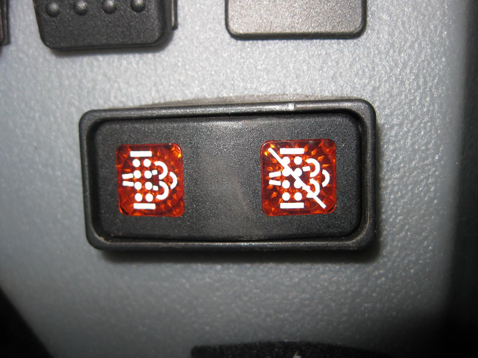
1.Auto Regen: The neutral center AUTO position of the switch allows the EECU to transparently perform low-level (self and assist) DPF regen, without operator input.
2.Stationary Regen Start: The left side of the switch is a momentary switch used for starting a stationary regen.
3.Stationary Regen Request Lamp: The lamp prompts the operator to implement a stationary regen. It is used for notifying the operator that the stationary regen request has been made by the E-ECU. This light will flash requesting stationary regen. After the switch is pressed for three seconds or more the light will change state indicating the engine is in stationary regen mode.
4.Inhibit Regen (Delay): The right side of the toggle switch is used for delaying Reset regen. The purpose of this feature is to prevent unexpected hot exhaust in situations that the heat could be dangerous. This will INCREASE the possibility of requiring a stationary regen. If the switch is placed in this position the E-ECU will not perform reset regen and soot may build up in the soot filter. This build up may also lead to a 50% reduction in engine power and a required soot filter replacement.
5.Inhibit Regen (Delay) Lamp: The lamp is used for notifying the operator that the inhibit switch has been activated which will delay reset regen.
Note: During regeneration, there may be a change in sound due to the intake throttle and the EGR (Exhaust Gas Recirculation) valve opening changes, but normal regeneration should otherwise be transparent to the operator. The exhaust may also smell different from non-DPF equipped diesel engines.
There is a possibility of carbon monoxide poisoning if the regen occurs in enclosed spaces. Be sure to allow for an outside air source or park the loader outside during a regen.
During regeneration there will be high exhaust gas temperatures, even at low load. Be sure to stay clear of the DPF during a regen.
The machine should not be used or moved when a stationary regen is being performed. If the machine must be moved, releasing the parking brake, moving the throttle, or cycling the key will interrupt the stationary regen and allow operation of the machine.
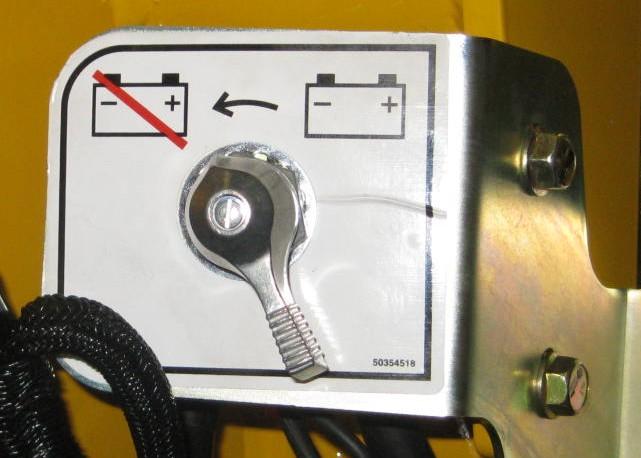
Electrical Battery Disconnect Switch
An electrical battery disconnect switch is located inside the engine compartment on the left side and forward of the fuse panel. Turn the switch to the OFF position to disconnect the battery from the electrical system.
Chapter 4 Operation
Before starting the engine and operating the loader, review and comply with all safety recommendations in the Safety chapter of this manual. Know how to stop the loader before starting it. Also, be sure to fasten and properly adjust the seatbelt(s) and lower the operator restraint bar.
Before Starting the Engine
Before starting the engine and running the loader, refer to the Controls and Safety Equipment chapter and become familiar with the various operating controls, indicators and safety devices on the loader.
Fuel
Non-DPF Models: The engine requires low sulfur or ultra-low sulfur diesel fuel to maintain proper engine performance. BioDiesel mixtures of up to a 5% (B5) are acceptable.
DPF Models: Use only ultra-low sulfur diesel fuel to maintain proper engine performance. Use of diesel fuel with more than 15 ppm of sulfur can potentially damage the engine. BioDiesel mixtures of up to a 5% (B5) are acceptable. UltraLow Sulfur Diesel (ULSD) fuel lubricity must have a maximum scar diameter of 0.45 mm, as measured by ASTM D6079 or ISO 12156-1, or a minimum of 3100 grams, as measured by ASTM D6078. Contact your fuel supplier for details. Static electricity can produce dangerous sparks at the fuel-filling nozzle. Do not wear polyester, or polyester-blend clothing while fueling. Before fueling, touch the metal surface of the machine away from the fuel fill to dissipate any built-up static electricity. Do not re-enter the machine but stay near the fuel filling point during refueling to minimize the build-up of static electricity. Do not use cell phones while fueling. Make sure the static line is connected from the machine to the fuel truck before fueling begins.
Ultra-Low Sulfur Diesel (ULSD) poses a greater static ignition hazard than earlier diesel formulations. Avoid death or serious injury from fire or explosion; consult with your fuel or fuel system supplier to ensure the entire fuel delivery system is in compliance with fueling standards for proper grounding and bonding practices.
Starting the Engine
The following procedure is recommended for starting the engine:
1.Carefully step up onto the back of the bucket or attachment and grasp the handholds to enter the operator’s compartment.
2.Close the door, fasten the seatbelt(s) and lower the restraint bar.
3.Verify the following:
the lift/tilt, drive and auxiliary hydraulic controls are in their neutral positions,
the parking brake switch is ON.
Note: When the key is turned to the RUN position, an indicator lamp will light on the instrument panel and a buzzer will sound momentarily to remind users to fasten the seatbelt.
4.Turn the key to the START position.
Note: If temperature is below 32°F (0°C), see Cold-Starting Procedure, on page48.
Important: Do not engage the starter for longer than 15 seconds at a time. Longer use can overheat and damage the starter. If the engine fails to start within 15 seconds, return the key to the OFF position or check for engine error codes. Allow the starter to cool for 20seconds and repeat step 4.
After the engine starts, allow a five minute low idle warm-up period before operating the controls.
Important: Avoid extended engine idling after the engine reaches normal operating temperature to prevent frequent DPF regens. If the indicator warning lamps do not go off, stop the engine and investigate the cause.
Cold-Starting
If the temperature is below 32°F (0°C), the following is recommended to make starting the engine easier:
Replace the engine oil with API-CJ-4/SAE 5W-30 oil as recommended by the viscosity chart;
Make sure the battery is fully charged;
Install a block heater on the engine. Let the engine run for a minimum of five minutes to warm the engine and hydraulic fluid before operating the loader. A block heater is recommended for starting in temperatures of 14°F (-10°C) or lower. See your dealer for heater options.
Cold-Starting Procedure
WARNING
Do not use starting fluid (ether) with pre-heat systems. An explosion can result, which can cause engine damage, injury or death.
1.Turn the key to the RUN position. If the preheat lamp symbol on the indicator and warning lamp display comes on, wait for this symbol to go out.
2.Immediately turn the key to the START position.
3.If engine does not start, return key to OFF position and repeat steps 1 and 2.
4.If equipped with the optional Power-A-Tach System, activate the warming circuit.
Important: During cold start conditions, the recommended limit of continuous starter engagement is 15 seconds and the starter must never be energized for more than 30 seconds. If the starter is energized for 20-30 seconds, the loader should be turned off for one minute or longer. To protect the starter, the E-ECU system turns off the starter circuit if it is energized for 30 seconds or longer. The starter will remain de-energized for 30 seconds more before the loader can be restarted.
Upon a successful start, let the engine run for a minimum of five minutes to warm the engine and hydraulic fluid before operating the loader.
Cold Start Aids
At an ambient temperature of 32° F (0° C) or below, no starting aids are required. However, as with any diesel vehicle, using the recommended engine oil, maintaining a healthy battery and installing an engine block heater are sound practices to improve cold-starting performance and prolonging starter life.
At an ambient temperature of 14° F (-10° C) or below, a healthy battery is essential as glow cycles and cranking cycles can induce a substantial load on the battery during start. An engine block heater is recommended at this temperature to reduce starter load and improve the engine warm-up period prior to loader operation. Attempting to start the loader without a block heater will result in multiple glow/crank cycles or possible extended cranking time approaching 20 seconds.
At an ambient temperature of 5° F (-15° C) or below, a healthy battery is imperative. A recommended battery charger/maintainer applied before or during a start cycle will help maintain 12 V to the starter circuit during a potential long crank cycle of 20 seconds or more. A required block heater will reduce starter load, reduce crank time and improve the overall engine warm-up time during extreme cold starts.
Speed Limit Protection During A Cold Start (Turbo DPF Models)
If the coolant or air temperature is 5° C (41°F) or less during startup, the maximum engine speed is limited to 1500 rpm for up to three minutes.
Note: Advancing the throttle during the rpm limit period will not increase engine speed above 1500 rpm. If the throttle is advanced above 1500 rpm during the rpm limit period, the throttle must be moved back below 1500 rpm once the limit period is over or the limit will remain in effect.
Automatic Idle-Up Speed During A Cold Start (Non-DPF Models)
Depending upon coolant temperature, 50° F (10° C) or below, the low idle engine speed will automatically increase to a maximum idle speed of 1280 rpm. The idle speed will then automatically return to the 1000 rpm normal idle speed after the five minute warm-up period or when the coolant reaches a specified temperature.
Stopping the Loader
The following procedure is the recommended sequence for stopping the loader:
1.Check that the drive control handle(s) is (are) in neutral position.
2.Lower the lift arm and rest the attachment on the ground.
3.Turn throttle knob back to the low idle position (and release the throttle pedal for dual joystick, dual hand and T-bar control machines). Allow the engine to idle for five minutes if the engine was operated under full load.
4.Turn the keyswitch to the OFF position and remove the key.
5.Move the lift/tilt control to verify that the safety interlock system is preventing movement.
6.Raise the restraint bar, unfasten the seatbelt(s) and grasp the handholds while climbing out of the operator’s compartment.
Note: The skid-steer loader is equipped with a spring-applied automatic parking brake. The parking brake is applied when the operator lifts the restraint bar, leaves the operator’s seat or shuts off the engine, or actuates the parking brake switch.
Parking the Loader
Park the loader away from traffic on level ground. If this is not possible, park the loader across the incline and block the tires to prevent movement.
Brake Release Operation (option)
The loader may have, as an option, a brake release system installed. Utilizing the brake release system disables the parking brake, allowing the loader’s wheels to freely move in either a forward or rearward direction.
Warning
Before utilizing the brake release, be sure to secure the vehicle with wheel chocks or tow lines. Verify the loader’s travel paths are clear of personnel before utilizing the brake release system.
1.Locate the brake release jack and handle. Depending on your particular model, it may be necessary to remove covers and/or open the rear door of the machine.
2.Remove any existing access cover.
3.Position the receiver and insert the jack handle.
4.Push the plunger on the receiver and hold.
5.Begin actuating the pump. Hydraulic pressure developed will retain the plunger so it no longer requires to be pushed. Continue to actuate the pump until the resistance of the jack handle does not increase. There is an internal relief valve in the jack assembly that prevents damage to the motor.
6.You may now tow the loader a short distance or pull it onto a trailer. Depending on the drive motor’s internal leakage rate, the loader may roll easily once the brake is released, or the tires may skid until the oil is forced from the motor.
7. The brake can be reset by pulling up on the plunger or starting the loader.
Jump-starting
If the battery becomes discharged or does not have enough power to start the engine, use jumper cables and the following procedure to jump-start the engine.
Warning
The ONLY safe method for jump-starting a discharged battery is for TWO PEOPLE to perform the following procedure. The second person removes the jumper cables so that the operator does not have to leave the operator’s compartment with the engine running. NEVER make jumper cable connections directly to the starter solenoid of either engine. DO NOT start the engine from any position other than on the operator’s seat and then ONLY after being sure ALL controls are in “neutral.”
Closely follow the procedure, in order, to avoid personal injury. In addition, to protect your eyes wear safety glasses and avoid leaning over the batteries while jump-starting.
DO NOT jump-start the battery if it is frozen, because it may rupture or explode.
Note: BE SURE the jumper battery is a 12-volt D.C. battery.
1.Turn the keyswitches of both vehicles to OFF, be sure the vehicles are in “neutral” and NOT touching each other.
2.Connect the positive (+) jumper cable to the positive (+) battery terminal on the disabled loader first. DO NOT allow the positive clamps to touch any metal other than the positive (+) battery terminals.
3.Connect the other end of the positive jumper cable to the jumper vehicle’s battery positive (+) terminal.
4.Connect the negative (-) jumper cable to the jumper vehicle’s battery negative (-) terminal.
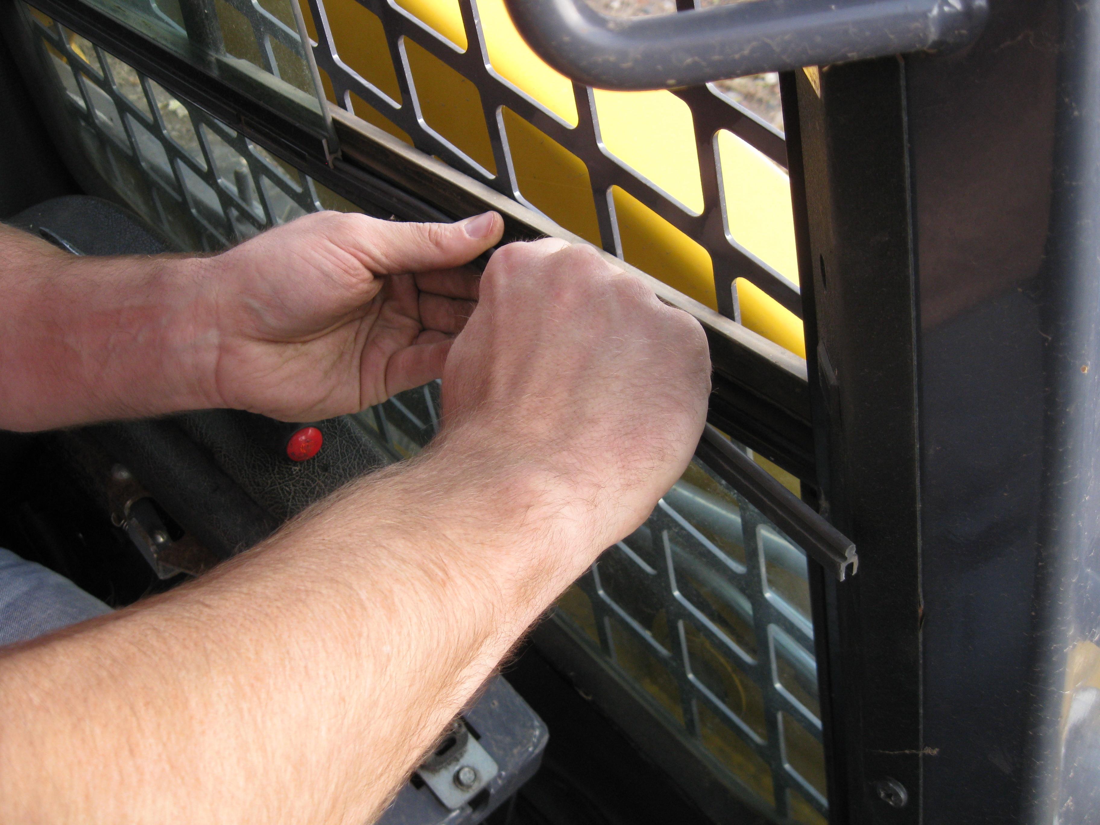
5.Make the final negative (-) jumper cable connection to the disabled loader’s engine block or loader frame (ground), such as the rear grille latch post –NOT to the disabled battery’s negative post. If connected to the engine, keep the jumper clamp away from the battery, fuel lines and moving parts.
6.Start the loader. If it does not start at once, start the jumper vehicle engine to avoid excessive drain on the booster battery.
7.After the disabled loader is started and running smoothly, have the second person remove the jumper cables (negative [-] jumper cable first) from the jumper vehicle’s battery and then from the disabled loader while being sure NOT to short the two cables together.
Allow sufficient time for the skid-steer loader alternator to build-up a charge in the battery before attempting to operate the loader or shut the engine off.
Changing Attachments
To prevent unexpected release of the attachment from the hitch, be sure to properly secure the hitch latch pins by rotating the latch levers fully (manual All-Tach® hitch), or by verifying that the pin flags moved fully to the outside of the hitch (Power-A-Tach ® hitch). Locking pins must be fully engaged through the holes in the attachment frame before using the attachment. The attachment could fall off if it is not locked on the hitch and cause serious injury or death.
On a manual hitch (Figure1), two latch levers engage the latch pins to secure the attachment.

Connecting Attachments
1. Manual hitch: Rotate the latch lever to the right as viewed from the front to fully retract the latch pins.
Power hitch: Activate the switch to unlock the hitch and fully retract the latch pins. (See page28 for a detailed description of this procedure.)
2.Start the loader engine and be sure the lift arm is lowered and in contact with the loader frame.
3.Align the loader squarely with the back of the attachment.
4.Tilt the hitch forward until the top edge of the hitch is below the flange on the back side of the attachment and centered between the vertical plates.
5.Slowly drive the loader forward and, at the same time, tilt the hitch back to engage the flange on the back side of the attachment.
6.Stop forward travel when the flange is engaged, but continue to tilt the hitch back to lift the attachment off the ground.
7. Manual hitch: Exercise the MANDATORY SAFETY SHUTDOWN PROCEDURE (page6). Leave the operator’s compartment and rotate the latch lever to the left when viewed from the front to fully engage the latch pins.
Power hitch: Press the Power-A-Tach switch in the right instrument panel to extend the hitch pins and to lock the hitch and fully engage the latch pins. After the pins are fully engaged, set the switch back to neutral (middle) to turn off the warming circuit. If the temperature is below 0° F (-18° C) it is recommended to leave the warming circuit on.
Note: It is safe to operate the loader with the warming circuit on or off, it won't affect the performance of the loader.
Important: To check that the attachment is properly installed tilt the attachment forward slightly, apply downward pressure to the attachment prior to operating.
Connecting Auxiliary Hydraulic Couplings
Note: The loader is equipped with quick couplers designed to release trapped pressure. The pressure is automatically released by pushing the coupler inward, returning the oil through the case drain line back to the loader.
Standard-Flow Auxiliary Hydraulics
Couplers are located on the left lift arm. When the auxiliary control switch is activated in either direction, the inside and outside couplers can be “pressure,” or “return” depending on which direction the switch is activated. The smaller center coupler is for the case drain.
High-Flow Auxiliary Hydraulics (optional)
Couplers are located on the right lift arm. When the auxiliary control switch is activated in either direction, the inside and outside couplers can be “pressure,” or “return” depending on which direction the switch is activated. The smaller center coupler is for the case drain.
Only connect high-flow attachment couplers to the high-flow auxiliary couplers.
Removing Attachments
1.Tilt the hitch back until the attachment is off the ground.
2.Exercise the MANDATORY SAFETY SHUTDOWN PROCEDURE (page6).
3.With the engine off, leave the operator’s compartment and disconnect the auxiliary hydraulic hoses.
4. Manual hitch: Rotate the latch lever to the right when viewed from the front to fully retract the latch pins.
Power hitch: Start the engine, press the top edge of Power-A-Tach switch on the right instrument panel to retract the hitch pins to unlock the hitch and fully retract the latch pins. Release the switch.
5.Start the engine (if it is not already on) and be sure that the lift arm is fully lowered and in contact with the loader frame.
6.Tilt the hitch forward and slowly back the loader away until the attachment is free from the loader.
Self-Leveling (optional)
The self-leveling feature is intended to automatically keep the attachment level while the lift arm is being raised. Self-leveling operates only when the lift arm is raised; when the lift arm is lowered, self-leveling is not activated.
Self-Leveling Cancel (optional)
The self-leveling cancel feature allows for the deactivation of the self-leveling feature. To deactivate self-leveling, press the top of the self-leveling cancel switch. To restore self-leveling, press the bottom of the self-leveling cancel switch.
Using a Bucket
Always maintain a safe distance from electric power lines and avoid contact with any electrically charged conductor or gas line. Accidental contact or rupture can result in electrocution or an explosion. Contact the “Call Before You Dig” referral system at 8-1-1 in the U.S., or 888-2580808 in the U.S. and Canada or proper local authorities for utility line locations before starting to dig.
Driving over Rough Terrain
When traveling over rough terrain, drive slowly with the bucket lowered.
Driving on an Incline
When traveling on an incline, travel with the heavy end pointing uphill.
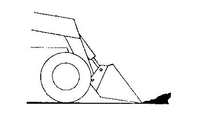
Digging with a Bucket
Approach the digging site with the lift arm slightly raised and the bucket tilted forward until the edge contacts the ground. Dig into the ground by driving forward and gradually lowering the lift arm (Figure2).
When the bucket is filled, tilt the bucket back, and back the loader away from the material. Rest the lift arm against the loader frame before proceeding to the dumping area.
Always carry the loaded bucket with the lift arm resting on the loader frame. For additional stability when operating on inclines, always travel with the heavier end of the loader toward the top of the incline.
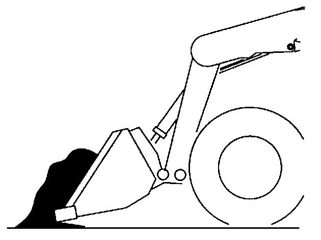
Loading a Bucket
Approach the pile with the lift arm fully lowered and the bucket tilted slightly forward until the edge contacts the ground. Drive forward into the pile, lifting the lift arm and tilting back the bucket to fill it. Back away from the pile (Figure3).

Dumping the Load onto a Pile
Carry a loaded bucket as low as possible until the pile is reached. Gradually stop forward motion and raise the lift arm high enough so that the bucket clears the top of the pile. Then, slowly move the loader ahead to position the bucket to dump the material on top of the pile. Dump the material and then back the loader away while tilting the bucket back and lowering the lift arm.
Warning
Never push the “float” button with the bucket or attachment raised, because this will cause the lift arm to lower rapidly. For more information, see page28.
Dumping the Load into a Truck (or Hopper)
Carry the loaded bucket low and approach the vehicle (or hopper.) Stop as close to the side of the truck (or hopper) as possible while allowing for clearance to raise the lift arm and loaded bucket. Next, raise the lift arm until the bucket clears the top of the truck (or hopper) and move the loader ahead to position the bucket over the inside of the truck (or hopper.) Dump the material and then back away while tilting the bucket back and lowering the lift arm (Figure4).
Dumping the Load over an Embankment
Warning
Do not drive too close to an excavation or ditch. Be sure the surrounding ground has adequate strength to support the weight of the loader and the load.
Carry the loaded bucket as low as possible while traveling to the dumping area. Stop the loader where the bucket extends half-way over the edge of the embankment. Tilt the bucket forward and raise the lift arm to dump the material. Dump the material, and then back away from the embankment while tilting the bucket back and lowering the lift arm.

Scraping with a Bucket
For scraping, the loader should be operated in the forward direction. Position the lift arm down against the loader frame. Tilt the bucket cutting edge forward at a slight angle to the surface being scraped. While traveling slowly forward with the bucket in this position, material can flow over the cutting edge and collect inside the bucket (Figure5).

Leveling the Ground
Drive the loader to the far edge of the area to be leveled. Tilt the bucket forward to position the bucket cutting edge at a 30 to 45degree angle to the surface being leveled. Then place the lift arm into “float” position and drive the loader rearward, dragging the dirt and, at the same time, leveling it (Figure6).
Note: For information on how the “float” detent is activated, see page28.
Check that the work area is clear of people and obstacles. Always look in the direction of travel.
Vibration Information
Compact construction equipment is generally used in harsh environments. This type of usage can expose an operator to uncomfortable levels of vibration. It is useful to understand exposure to vibration levels when operating compact equipment and what can be done to reduce vibration exposure. As a result, equipment operation can be more efficient, productive and safe.
An operator’s exposure to vibration occurs in two ways:
Whole-Body Vibration (WBV)
Hand-Arm Vibration (HAV)
This section will cover primarily WBV issues, because evaluations have shown that operation of mobile compact construction equipment on jobsites typically results in HAV levels less than the allowed exposure limit of 2.5 m/s2.
Employers in Member States of the European Union must comply with the Physical Agents (vibration) Directive, 2002/44/EC.
Effective control of vibration exposure for an operator involves more than just vibration levels on the machine. The job site, how the machine is used, and proper training all play important roles in reducing vibration exposure.
Vibration exposure results from:
worksite conditions
how the machine is operated
the machine characteristics
Common causes of high WBV vibration levels:
Using a machine that is improper for the task
Work site with potholes, ruts and debris
Improper operating techniques, such as driving too fast
Incorrect adjustment of the seat and controls
Other physical activities while using the machine
Vibration Measurement and Actions
The vibration directive places the responsibility for compliance on employers. Actions that should be followed by employers include:
Assess the levels of vibration exposure.
Determine from this assessment if operators will be exposed to vibration levels above the limits stated in the directive.
Take appropriate actions to reduce operator’s exposure to vibration.
Provide operators with information and training to reduce their exposure to vibration.
Keep good records and update operations and training on a regular basis. If the assessment concludes that vibration level exposure is too high, one or more of the following actions may be necessary:
1.Train operators
Perform operations (accelerating, steering, braking, etc.) in a smooth manner.
Adjust machine speed appropriately.
Adjust the controls, mirrors and seat suspension for comfortable operation.
Travel across the smoothest parts of the work site and avoid ruts and potholes.
2.Choose proper equipment for the job
Use machines with the proper power and capacity.
Select machines with good suspension seats.
Look for controls that are easy to use.
Ensure good visibility from the operator’s position.
3.Maintain the work site
Smooth ruts and fill potholes in traffic areas whenever possible.
Clean up debris frequently.
Vary traffic patterns to avoid exposure to rough terrain.
4.Maintain the equipment
Ensure correct tire pressures.
Check that seat suspension and all controls work smoothly and properly.
Vibration Levels
The following two tables show typical Whole-Body and Hand-Arm Vibration levels for the Gehl V270 and V330 pilot-controlled and servo-controlled skidsteer loaders with their different seat options.
Pilot Whole-Body and Hand-Arm Vibration Levels*
*Whole-Body Vibration levels in accordance with ISO 2631-1. Hand-Arm Vibration levels in accordance with ISO 5349-1.
Servo Whole-Body and Hand-Arm Vibration Levels*
*Whole-Body Vibration levels in accordance with ISO 2631-1. Hand-Arm Vibration levels in accordance with ISO 5349-1.
Highway Travel
If it becomes necessary to move the loader a long distance, use a properly rated trailer. (See Transporting/Towing the Loader on page60.) For short distance highway travel, attach an SMV (Slow-Moving Vehicle) emblem (purchased locally) to the back of the loader. For highway operation, install the optional amber strobe light. Check state and local laws and regulations.
Storing the Loader
If the skid-steer loader is to be stored for a period in excess of two months, the following procedures are suggested:
1.Fully inflate the tires.
2.Lubricate all grease zerks.
3.Check all fluid levels and replenish as necessary. (Review and follow the engine manufacturers recommendations from the Engine Operator’s Manual.)
4.Add stabilizer to the fuel per the fuel supplier’s recommendations. If the fuel has a mixture of BioDiesel, empty the fuel tank before storing.
5.Turn the electrical battery disconnect switch to its OFF position and remove the battery, charge it fully and store in a cool, dry location.
6.Protect against extreme weather conditions such as moisture, sunlight and temperature.
Removing Loader from Storage
1.Check the tire air pressure and inflate the tires if they are low.
2.Connect the battery and check that the electrical battery disconnect switch is turned to its ON position.
3.Check all fluid levels (engine oil, transmission/hydraulic oil, engine coolant and any attached implements). (Review and follow the engine manufacturers recommendations from the Engine Operator’s Manual.)
4.Start the engine. Observe all gauges. If all gauges are functioning properly and reading normal, move the machine outside.
5.Once outside, park the machine and let the engine idle for at least five minutes.
6.Shut the engine off and walk around machine. Make a visual inspection looking for evidence of leaks.