5 minute read
PREPARING FOR FIELD OPERATION

Tractor Requirements
The tractor used to operate a Disc Mower Conditioner, MUST have:
1.A minimum of 85 hp (64 kW)
2.A 1000 RPM PTO matching the operating speed of the Disc Mower Conditioner.
3.PTO and hitch dimensions as shown.
4.Two remote hydraulic outputs capable of powering a double-acting cylinder. A minimum operating pressure of 1800 PSI (12.4 MPa) is required to lift the Disc Mower Conditioner.
5.It is recommended that the towing tractor be equipped with an enclosed operator’s cab with safety glass or polycarbonate windows, or with protective mesh screens.
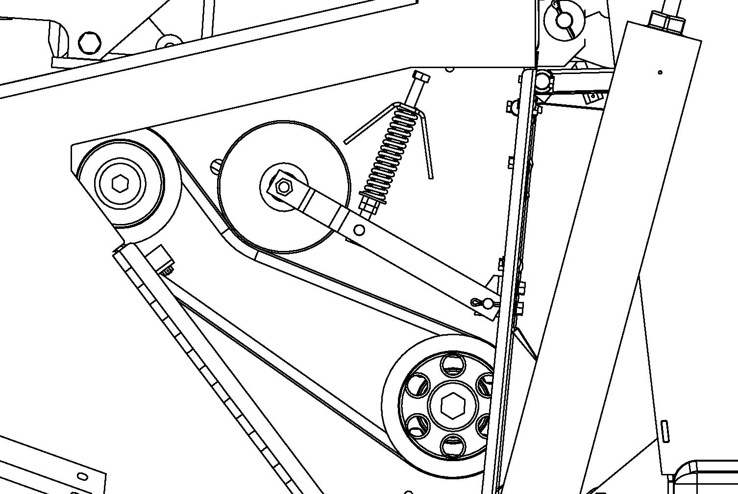
IMPORTANT: If this unit is connected to a tractor equipped with a clevis-style drawbar, the clevis parts shown in dashed lines MUST be removed to prevent damage to the unit driveline. See Fig. 34.
Attachment To Tractor
IMPORTANT: Whenever the Disc Mower Conditioner is operated on a tractor other than the original tractor the unit was set up for, the drawbar height and header flotation must be checked and adjusted accordingly.
Tractor Drawbar Requirements, 3-Point Hitch (Fig. 35)
Adjust the tractor hitch to meet Dimension 5 in Figure 35. Position the drawbar left or right of center. Also adjust the tractor hitch turnbuckles so that the distance between universal cross centers on the tractor to implement PTO is between 23 to 33 inches (585 to 838 mm) throughout the full range of tractor hitch motion.
IMPORTANT: DO NOT exceed the listed dimensions, or damage to the tractor and Disc Mower Conditioner will occur.
Hitch Positions (Fig. 36)
The Disc Mower Conditioner hitch can be set up to fit category II and category III 3-point and quick hitches. The Disc Mower Conditioner hitch mounting width is changed by exchanging the hitch brackets mounting positions. Hitch pin diameters are changed by adding or removing hitch bushings. Hitch bushings are stored in the toolbox when not in use.
NOTE: The bolt pattern in the hitch and hitch brackets is such that the hitch brackets MUST be switched side-to-side, and not turned over. The hitch bracket is properly installed when the flared flanges face downwards.
Tractor Drawbar Requirements, Clevis Hitch (Fig. 37)
Adjust the tractor drawbar to meet dimension No. 3 in Fig. 37 to avoid damage to the front telescoping PTO Drive. Adjust the drawbar left or right to place the hitch pin hole directly in line with the PTO Shaft.
IMPORTANT: To prevent damage to the Disc Mower Conditioner telescoping drive, PTO tower and tractor PTO shaft, avoid making sharp turns.
1 – Tractor PTO Shaft (Tractor MUST comply with ASAE Standard S203).
2 – 6″ to 12″ (152 to 305 mm) [8″ (203 mm) preferred] This is measured from the center of the tractor PTO shaft to the top of the tractor drawbar at the hitch pin hole.
3 – 16″ (406 mm) for 1000 RPM operation. This is measured from the end of the Tractor PTO Shaft to the center of the Hitch Pin.
4 – 34-1/2″ (845 mm) for 1000 RPM operation. This is measured from the retaining groove in the Implement Input Drive Shaft to the center of the Implement Hitch Hole.
5 – 13″ to 22″ (330 to 560 mm) [18″ to 20″ (457 to 508 mm) preferred] This is measured from the top of the tractor drawbar at the hitch pin hole to level ground.
6 – 0″ to 3″ (0 to 76 mm) Tire Bumper Extension Kit NOT required; 3″ to 6″ (76 to 152 mm) optional Tire Bumper Extension Kit required (see Optional Equipment and Accessories chapter of this manual), 6″ and above, DO NOT use tractor with this hitch as driveline damage will occur.
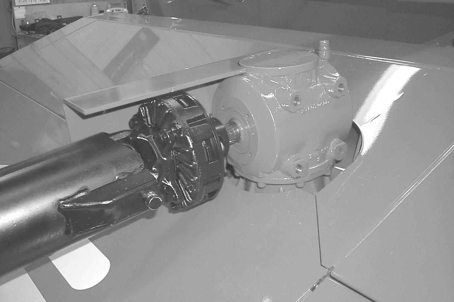
PTO
Clean and lightly grease the splines on the tractor PTO shaft and the yoke of the telescoping drive. Depress the safety lock ring and slide the yoke onto the tractor PTO shaft. Move the yoke back and forth until the safety lock ring pops forward and locks into the groove in the PTO shaft.
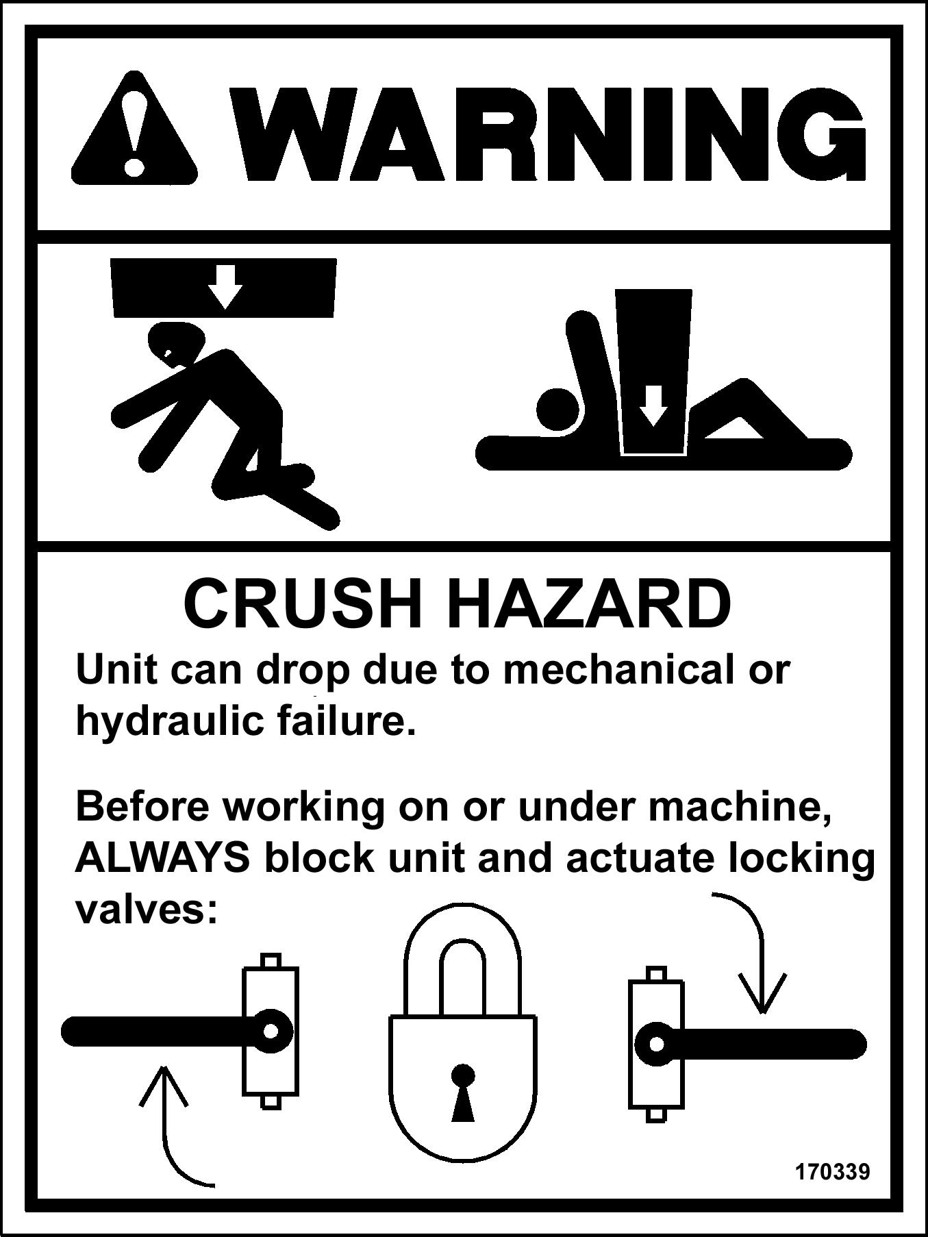
Warning
BE SURE that the PTO safety lock ring is positively engaged and that the tongue is securely connected to the tractor 3-point hitch with the supplied locking pins or to the tractor drawbar with a locking clip pin BEFORE starting the tractor engine. Also, BE SURE that the tractor PTO shield is in place and properly secured and that the telescoping drive shields rotate freely BEFORE starting the tractor engine.
Hydraulic Lift
Install the supplied quick-disconnect fitting (to match your tractor connection) onto the lift cylinder hose (left hose). Make the lift cylinder hose attachment to the tractor, start the tractor and operate the valve to raise and lower the Disc Mower Conditioner several times to purge the air out of the system.
IMPORTANT: If the Disc Mower Conditioner is NOT horizontal when it is being raised and lowered, refer to the Service chapter for corrective measures.
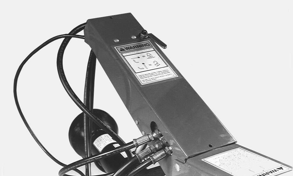
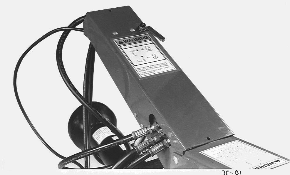
STEERING AND LIFT CYLINDER HOOKUP (Fig. 38)
The two hoses (2 right hoses) from the steering cylinder should be hooked up so that when the tractor control handle is moved to the forward position the header will move to the right. (Pressure from this line will retract the steering cylinder). Moving the control handle to the rearward position will move the header to the left. (Pressure on this line will extend the steering cylinder.) The lift cylinder hose should be connected to another valve so when the control handle is pulled to rear position the entire machine will raise. The operator may prefer to position the cylinder connections differently for more efficient use of the control handles during field operation.
1 – Remote Hydraulic Levers – Typical Arrangement
2 – Steer Right
3 – Lower Entire Machine and Tilt Header Down
4 – Right Hydraulic Lever
5 – Steer Left
6 – Tilt Header Up and Raise Entire Machine
Fig. 38
Warning
Do NOT remove hydraulic tongue control cylinder with conditioner header off the ground. Failure to heed can result in death or serious injury.
NOTE: Operation of the tongue control cylinder requires a tractor with two remote hydraulic outputs, one for the tongue control and another for the lift control.
CUTTING HEIGHT & HEADER FLOTATION
Adjust the cutting height and header flotation following information in the adjustments chapter of this manual.
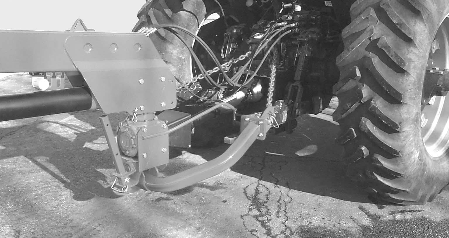
SAFETY CHAIN (Fig. 39)
Only a safety chain (NOT an elastic or nylon/plastic tow strap) should be used to retain the connection between the towing and towed machines, in the event of separation of the primary attaching system. Refer to Optional Equipment & Accessories chapter for part number information.
BREAK-IN
Before starting to cut and condition, it is recommended that the Disc Mower Conditioner be broken-in by running it empty for approximately 20 minutes. This initial run-in should be done with the header on the ground. Before running the unit however, perform the daily (10 hour) maintenance routines listed in the beginning of the Operation chapter.
The break-in should consist of a five minute and a fifteen minute running period. First, run the unit for five minutes with the tractor engine close to idle RPM. Next, stop the unit and exercise the MANDATORY SAFETY SHUTDOWN PROCEDURE (page 8). Reinspect the unit. After inspection is complete, connect the PTO, start the tractor, engage the PTO near engine idle speed and gradually increase the speed to proper operating RPM and continue running the machine for 15 minutes. Stop the unit and exercise the MANDATORY SAFETY SHUTDOWN PROCEDURE (page 8) again. After another inspection, the Disc Mower Conditioner is ready for the field.

IMPORTANT: The oil in the cutterbar and the gearboxes MUST be changed after the first 10 hours of operation. For details, see the Lubrication chapter of this manual.
Transporting
BEFORE transporting the Disc Mower Conditioner, refer to the Transporting chapter of this manual for additional transporting information.