17 minute read
CHAPTER 5 CONTROLS & SAFETY EQUIPMENT

The Disc Mower Conditioner is provided with several features for operator safety and convenience.
Warning
BEFORE operating this equipment, become familiar with ALL safety devices and controls. Know how to STOP the Disc Mower Conditioner operation BEFORE starting it.
Drawbar Hitch Positioning Warning
BEFORE transporting the mower conditioner on a public highway, BE SURE to lock the positioner cylinder in the “transport” position with the transport lock valve.
Repositioning the Disc Mower Conditioner tongue between the “Transport” and operating positions can be accomplished hydraulically.
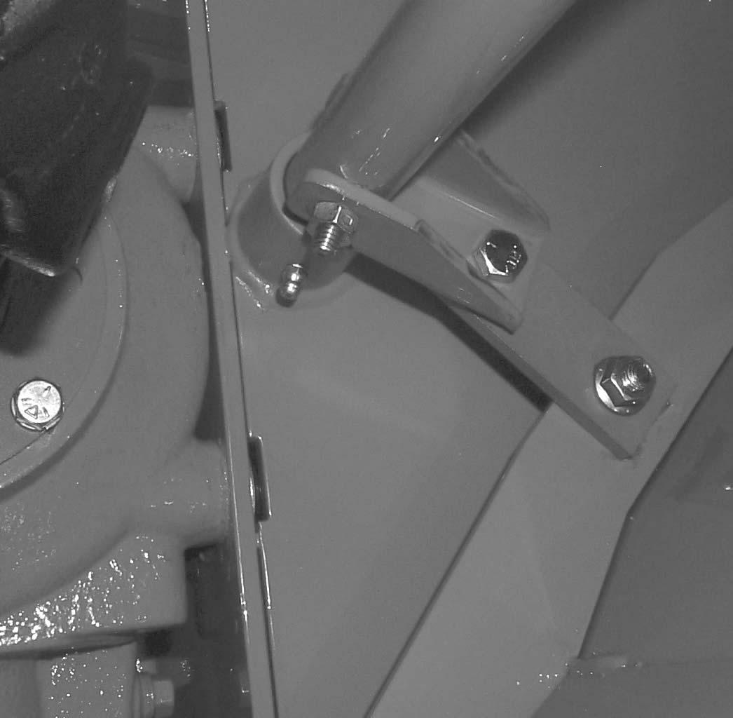
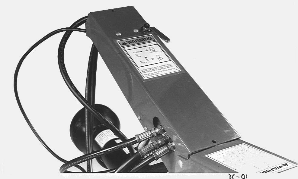
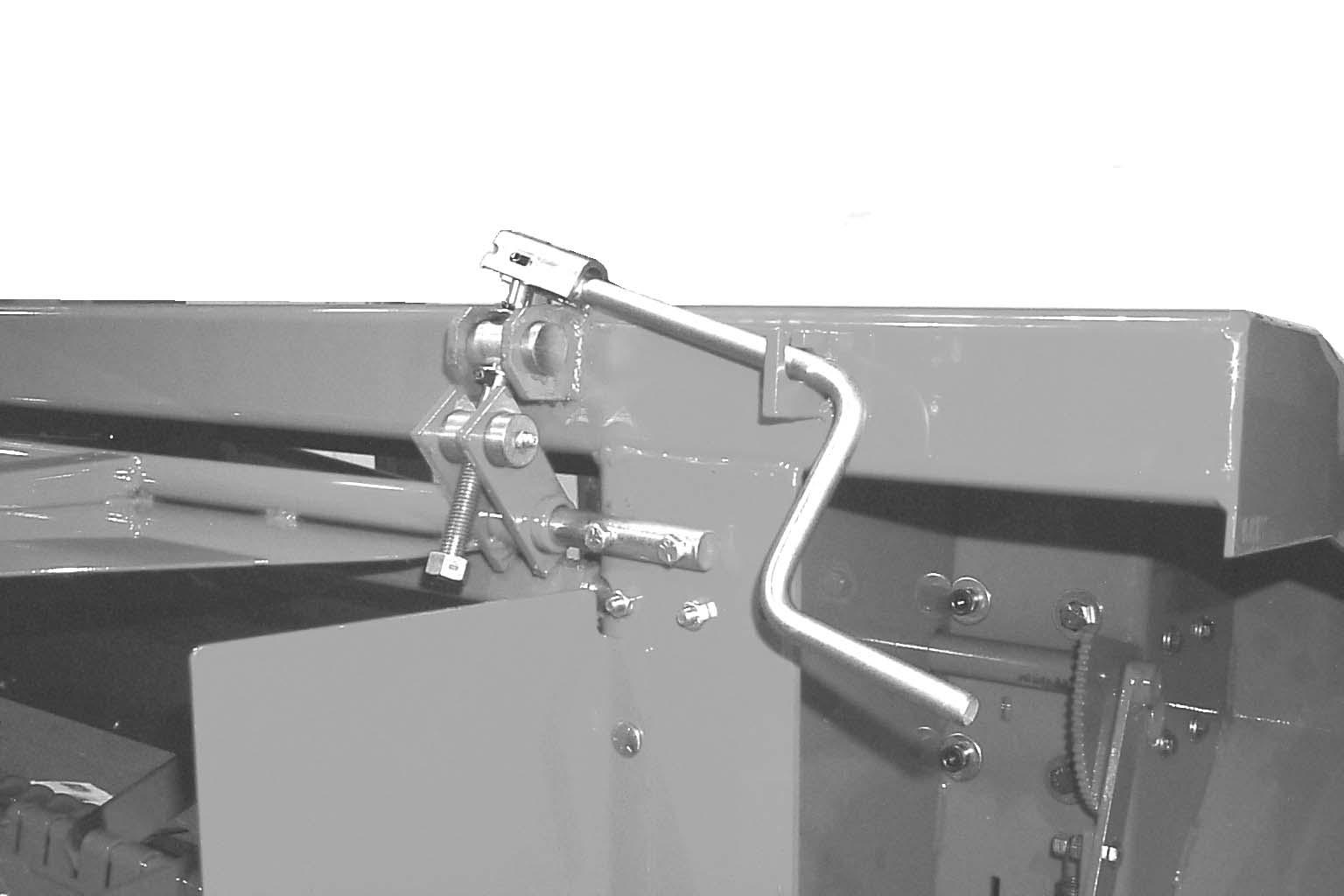
Hydraulic Hitch Positioner (Figs. 1 & 2)
The Disc Mower Conditioner is equipped with a hydraulic hitch positioner for remotely (from the tractor seat) relocating the drawbar from the centered “Transport” position to the various field operation positions. The hydraulic hitch positioner contains a double-acting hydraulic cylinder, hoses and a transport lock valve.
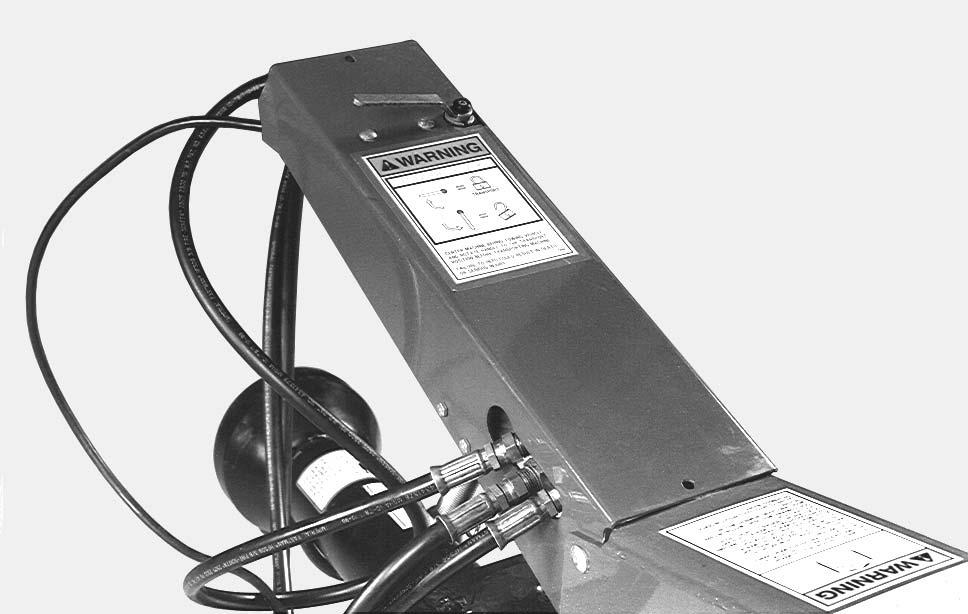
When the Disc Mower Conditioner is in use in the field, the transport lock valve should be in the “open” position. When the Disc Mower Conditioner is centered behind the tractor in the transport position, the transport lock valve MUST be in the “Transport” position. Keep transport lock valve in the “Transport” position only during transport of the unit.
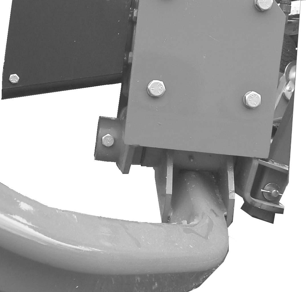
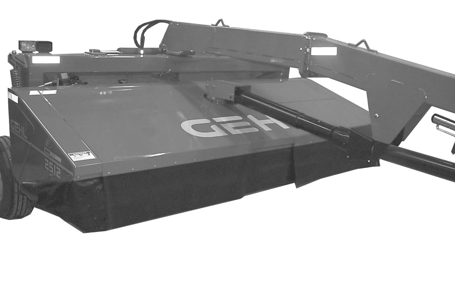
GUARDS & SHIELDS (Figs. 3 & 4)
Whenever and wherever possible and without affecting machine operation, guards and shields have been used on this equipment to protect potentially hazardous areas. In many places, decals are also provided to warn of potential hazards as well as to display special operating procedures.
Warning
Read and observe ALL warnings on the unit BEFORE operating it. DO NOT operate this equipment unless ALL guards and shields are properly secured in place.
Implement Drive Line Shields

The front telescoping PTO drive, between the PTO Tower and tractor PTO shaft, and the rear telescoping PTO drive, between the center PTO tower and gearbox, are equipped with rotating shields. The center driveline shield is stationary.
Warning
BE SURE that the rotating shields on the drives turn freely BEFORE starting the tractor engine. BE SURE any damaged or worn guard, shield, curtain or cover is replaced BEFORE operating the disc mower conditioner.
Warning
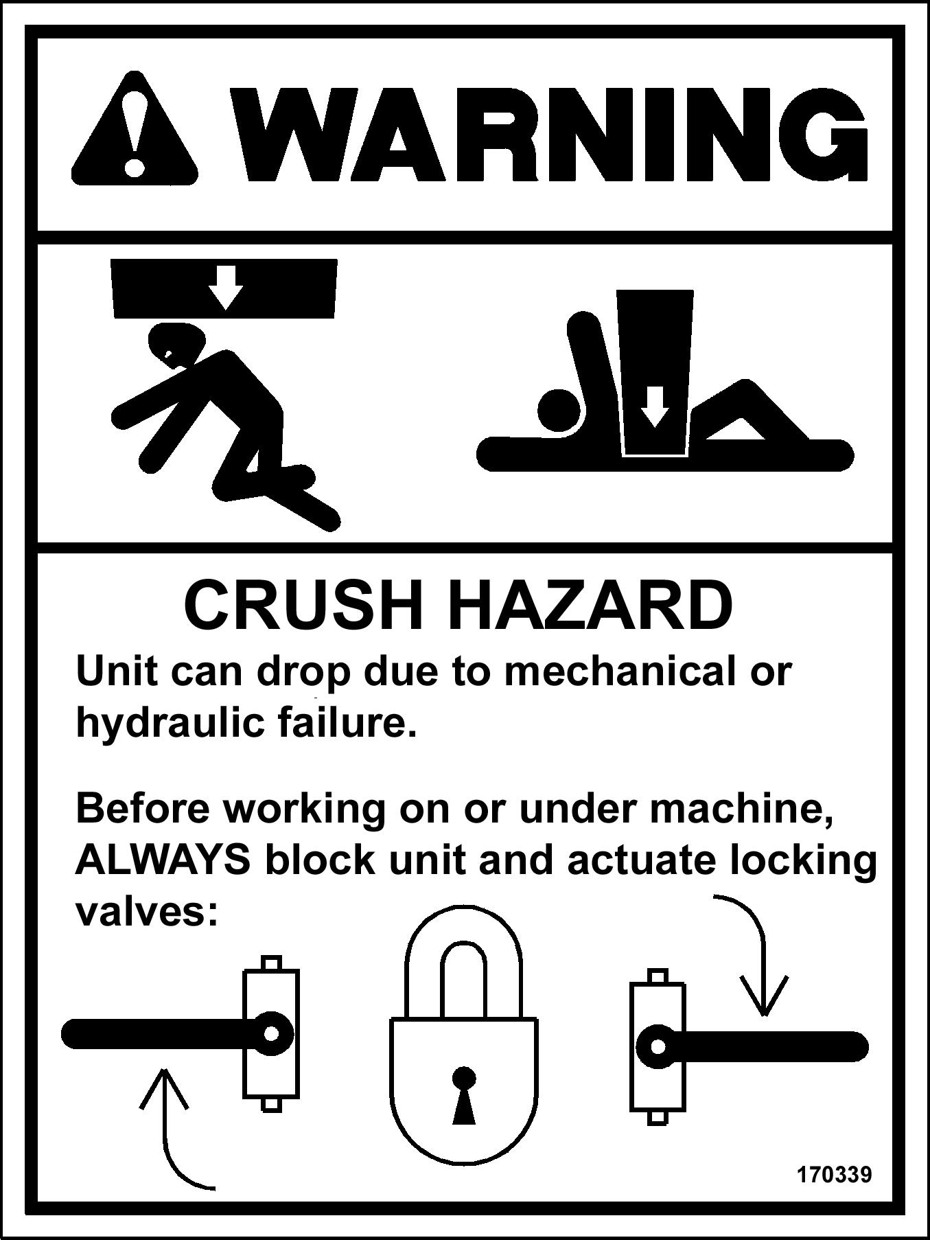
BEFORE performing any work on the disc mower conditioner, and BEFORE removing any guards or opening any covers or shields, BE SURE to exercise the MANDATORY SAFETY SHUTDOWN PROCEDURE (page 8). Also, BE SURE to replace ALL guards, shields and covers BEFORE operating the unit.
HITCHJACK (Fig. 4)
Miscellaneous Guards
Various latched and hinged guards, shields, curtains and covers are provided on the Disc Mower Conditioner to enable access for lubrication, service and adjustment.
On tractor drawbar attaching models, a hitchjack is furnished with the Disc Mower Conditioner to support the machine when the tractor is disconnected as well as to facilitate aligning the hitch with the tractor drawbar for hookup. When the jack is NOT being used to support the Disc Mower Conditioner, it can be removed and relocated to a “storage” position on the conditioner tongue.
Warning
BE SURE the locking pin is properly seated into the holes through the jack tube and the “Support Position” hub on the drawbar BEFORE disconnecting the mower conditioner from the tractor.
HEADER LIFT SYSTEM (Fig. 5)

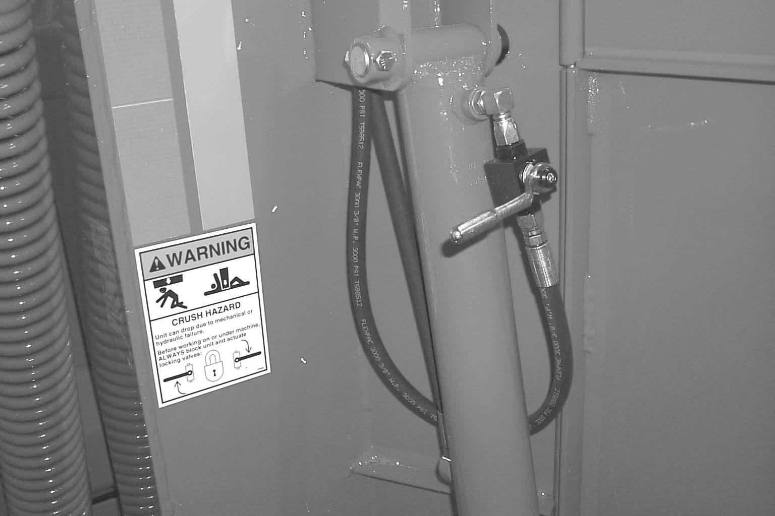
The Disc Mower Conditioner uses a remotely controlled (from the tractor seat) single-acting hydraulic cylinder “master-slave’’ system, to raise and lower the header. Before transporting the unit, BE SURE to raise the unit as high as possible and activate the transport lock valves on each side of the unit.
Warning
BEFORE transporting the disc mower conditioner, raise the unit as high as possible and engage both transport lock valves.
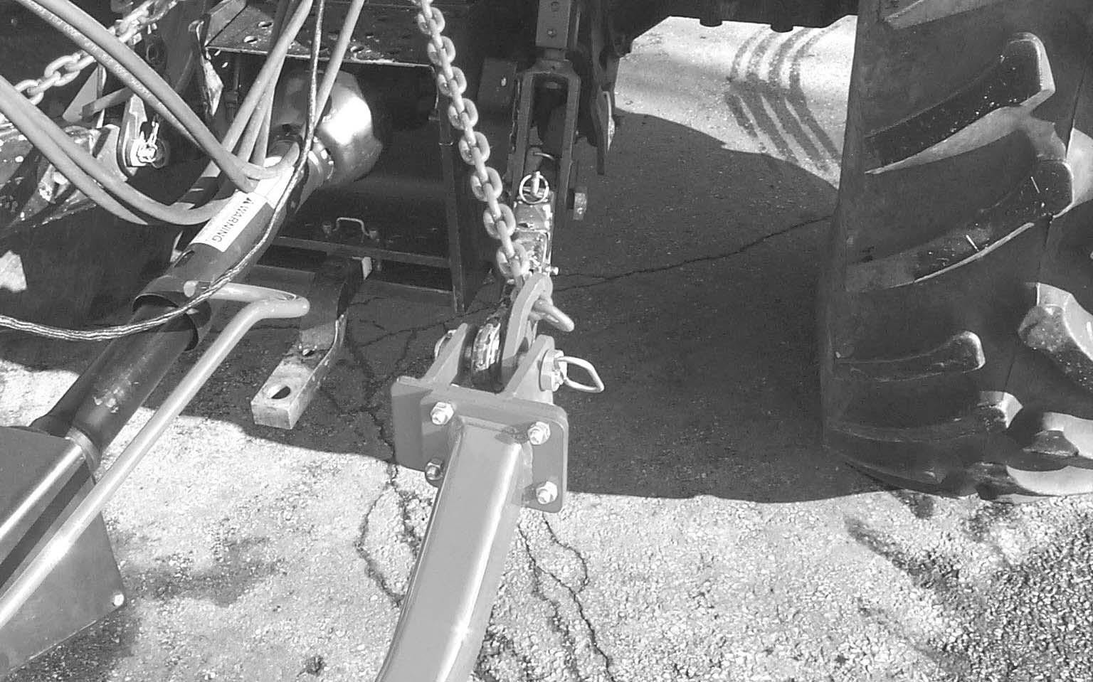
SAFETY CHAIN (Fig. 6)
Warning
ALWAYS follow state and local regulations regarding a safety chain (NOT an elastic or nylon/plastic tow strap) when towing farm equipment on public highways! A safety chain should always be used, to retain the connection between the towing and towed machine, in the event of separation of the primary attaching system. BE SURE to check with local law enforcement agencies for your own particular regulations.

As required or when desired, the Disc Mower Conditioner should be equipped with a safety chain for transporting the unit on public highways. A sturdy chain loop is welded to the side of the drawbar to facilitate anchoring the chain. Refer to the Optional Equipment & Accessories chapter for ordering information.
TRANSPORT LIGHTS (Fig. 7)
The Disc Mower Conditioner is equipped with transport lights as standard equipment. For your safety and the safety of others, it is recommended that you use the transport lights when traveling on public roadways. If your tractor is not equipped with a seven-prong auxiliary lighting receptacle, see your tractor dealer for installation of the required wiring. For additional information and regulations on transport lighting, check with your local law enforcement agency or your GEHL dealer.
TELESCOPING DRIVE COUPLER (Fig. 4)
The front telescoping drive is equipped with a springloaded locking device to positively lock it onto the tractor PTO shaft. The locking device stays depressed against spring tension when the PTO is not attached to the tractor. Slide the yoke onto the tractor PTO shaft releasing the locking device. Move the yoke ahead or back until the lock engages into the groove of the PTO shaft. When towing the Disc Mower Conditioner behind a vehicle that does not have a PTO drive shaft to secure the front drive line to, the drive Line MUST be removed from the Disc Mower Conditioner. DO NOT move Disc Mower Conditioner with the front drive line setting on drive line storage prop.
Warning
BE SURE that the telescoping PTO coupler is properly secured to the tractor PTO shaft and unit tower shaft BEFORE starting the tractor engine.
TRANSPORT LOCK VALVES (Figs. 1,
2 & 5)
When the Disc Mower Conditioner is to be transported on a public highway, BE SURE to raise the unit all the way up and actuate both right and left header lift system transport lock valves. BE SURE to also swing the drawbar to the centered transport position and place the transport lock valve in the “Transport” position.
Chapter 6 Operation Caution
BEFORE starting the tractor engine and running the disc mower conditioner for the first time, review and comply with ALL safety recommendations set forth in the SAFETY chapter of this manual.
Emergency Shutdown
In an emergency or in case a foreign object enters the header area, STOP cutting material IMMEDIATELY by disengaging the tractor PTO. Then, exercise the MANDATORY SAFETY SHUTDOWN PROCEDURE (page 8) BEFORE leaving the tractor seat to remedy the problem.
Warning
BE SURE ALL factory installed guards and shields are properly secured in place BEFORE starting the tractor engine. BE SURE that NO people are within 100 feet (30 m) of the unit when engaging the PTO. Never operate with curtain in raised position. Do NOT engage PTO unless unit is in the working position.
START-UP
To avoid unnecessary strain on the Disc Mower Conditioner drive line components, ALWAYS engage the tractor PTO slowly with the tractor engine at less than half throttle. Bring the unit to PTO speed BEFORE starting to cut. Always operate at PTO speed! Attempting to operate at higher than PTO speed could cause excessive vibration, wear and early component failure. In addition, operating the unit at slower than PTO speed will cause poor windrow formation and increase the chances of plugging.
Ground Speed
The Disc Mower Conditioner can be operated in a wide range of ground speeds depending on crop conditions and/or terrain. Any change in ground speed should be made by changing tractor gears and NOT by increasing or decreasing tractor engine RPM. Slow down when turning or traveling over rough ground.
Unplugging
It is possible for the Disc Mower Conditioner to plug in two different areas. It can become plugged in the disc area slipping the drive line clutch, or the unit can become wrapped in the conditioner rotor causing the belt to slip or the drive line clutch to slip.
Plugged Discs
To clear a plugging condition in the area of the discs:
1.Shut off the PTO.
2.Raise the header all the way up.
3.Exercise the MANDATORY SAFETY SHUTDOWN PROCEDURE (page 8).
4.Actuate both header transport lock valves.
5.Carefully clear the plug from the cutterbar area.
6.If the plugging occurs frequently, refer to the Troubleshooting chapter for additional directives.
Wrapped Conditioning Rotor
To clear wrapping from the Conditioning Rotor, proceed as follows:
1.Raise the unit fully.
2.Exercise the MANDATORY SAFETY SHUTDOWN PROCEDURE (page 8).
3.Actuate both header transport lock valves.
4.Open front covers on the header and remove excess material from the rotor by cutting with a suitable device.
5.Clear all crop from in front of the rotor. Be sure that no foreign objects are in front of the cutterbar or the rotor.
IMPORTANT: MAKE SURE to close covers before resuming cutting. Tongue will damage covers unless closed.
6.If the plugging occurs frequently, use this manual as a guide to check the following. (See the Troubleshooting chapter for additional information.):
– Tractor speed
– Condition of cutterbar knives.
– Position of the conditioning hood.
– Conditioner belt tension
– Swathboard and windrow sheet adjustment.
Starting The Field
After the field has been checked and is known to be free of obstructions, it can be opened by cutting the first swath in either direction. However, it is recommended to make two or three rounds first to expose any potential hazards around the edge of the field. Then, to cut and condition the backswaths by operating in an opposite direction around the field.
Steering
Steering the DC2512 is controlled by the tractor remote hydraulic system and allows the Mower Conditioner to follow directly behind the tractor, or make a full cut to either side, or an infinite number of positions in between.
Warning
Do not activate steering system without being sure no person or object will be hit as frame and header move.
The hydraulic hoses should be connected to the tractor so that by moving the tractor control lever forward, the Mower Conditioner steers right; by reversing the lever, the Mower Conditioner steers left. The controls are operated momentarily for steering and must be returned to OFF or NEUTRAL position as soon as the Conditioner reaches the desired path of travel. The second control lever, when moved back, lifts the header from the cutting position and when moved forward, lowers the header.
The center pivot provides the operator the opportunity to move the Mower Conditioner into field position easily, allowing right angle turns in either direction, steering around objects on both sides, and straight line field cutting on either side of tractor, as shown in Fig. 8.
180 Degree Turnaround
When it is desired to cut back and forth on one side of the field, approximately 4 to 6 cutting widths are required on each end of the field to make a 180 degree turnaround. The turn is accomplished as follows: Beginning at Position 1 in Fig. 9, the tractor is guided away from the uncut crop while the Disc Mower Conditioner is guided straight ahead until cutting through the end. As soon as the discs cut through, raise the header to lift the skid shoes clear of the cut crop and then begin to steer the Disc Mower Conditioner to the direction away from the uncut crop. At Position 2, the
Turnaround
tractor is guided back towards the uncut crop. In turning, MAKE SURE that the inside tractor tire does not contact the tongue of the Disc Mower Conditioner. In Positions 3 and 4, continue the turn towards the uncut crop with the Disc Mower Conditioner steered towards the outside of the circle, being aware of the tongue and tire caution, At Position 5, the tractor has completed the circle and the front wheels are turned to line up with the last cut windrow to straddle it. At this point, the Disc Mower Conditioner direction should be changed to line up with the edge of the uncut crop. Also, be prepared to lower the header to cutting height.
Disc Mower Conditioner to the extreme direction away from the uncut crop. As the tractor passes the corner, steer it sharply back towards the corner, but MAKE SURE that the inside tractor tire does not contact the tongue. Guide the tractor to straddle the last cut windrow. As the Disc Mower Conditioner completes its turning, be ready to steer it towards the uncut crop and align the header with edge of the uncut crop.
OVERLOAD PROTECTION (Fig. 11)
The Disc Mower Conditioner is protected with a slip clutch on the main driveline to protect the cutterbar and the impeller.

Turning Square Corners
The following procedure and diagram shown in Fig. 10 are intended only as a guide to aid the operator in setting up a turning procedure for the particular tractor being used. Distances are not specified due to the variations in tractor maneuverability. As the tractor approaches the corner, guide the tractor sharply away from the crop. The header is steered to maintain a straight cut ahead as the tractor moves away from the crop. As soon as the header cuts past where the new corner will be, steer the
Chapter 7 Adjustments
Warning
BEFORE performing any adjustments on this unit, exercise the MANDATORY SAFETY SHUTDOWN PROCEDURE (page 8).
The DC2512 Disc Mower Conditioner has been designed and factory adjusted to function properly under most field operating conditions. However, due to the wide range of operating conditions encountered, some additional adjustments may be required.
Warning
BEFORE adjusting the cutting height, exercise the MANDATORY SAFETY SHUTDOWN PROCEDURE (page 8).
HEADER FLOTATION (Fig. 12)
NOTE: BE SURE to place the header in the operating position before adjusting the flotation.
The header flotation is adjusted by varying the setting of the flotation spring on each end of the header. Lower the header to the operating position, loosen the jam nuts and tighten or loosen the spring bolts to achieve the desired flotation. In rocky or rough conditions, the flotation should be set lighter to protect the cutterbar. At higher mowing speeds, heavier settings follow terrain better. The flotation should be set as light as possible but heavy enough to follow the ground.
IMPORTANT: Any change of cutting height or drawbar height will change the header flotation. BE SURE to readjust the flotation, if necessary, to avoid damage.
1
2
3
CUTTING HEIGHT (Fig. 13)
The cutting height can be adjusted from 3/4″ (19 mm) to 3-1/2″ (89 mm) using the disc angle adjustment.
NOTE: Any change to the cutting height requires that the flotation be checked and readjusted, as necessary.
DISC ANGLE (Figs. 13 & 14)
The disc angle is adjustable from 0° (3-1/2″, 89 mm cutting height) to 8° down (3/4″, 19 mm cutting height). In rocky or rough conditions, use a flatter or 0° disc angle to protect the disc blades. In down, tangled and lodged crops, use a steeper or 8° disc angle to obtain a clean cut.
To change the disc angle, it is necessary to move the rear pivot of the top link rearward (0°) or forward (8°). To prepare to adjust the Disc angle, raise the unit to the transport height, engage the transport lock valves but do NOT remove hydraulic pressure from the system.

Warning
Exercise the MANDATORY SAFETY SHUTDOWN PROCEDURE (page 8) BEFORE adjusting the disc angle.
To change the disc angle, place the clevis pin in the desired height location shown in Figure 14. The pin acts as a downstop when hydraulic pressure is removed from the unit to change from transport to operating position. Applying lift system pressure will raise the Cutterbar to the highest position before raising the conditioner.

IMPORTANT: A disc angle change will change the header flotation. To avoid damage, BE SURE to readjust the header flotation after changing the disc angle.
IMPORTANT: DO NOT place adjusting clevis pin in a hole behind the sliding plates when the header is tilted forward or damage may occur.
Skid Shoes
The skid shoes are located on the underside of the cutterbar frame and are NOT adjustable.
″ (19
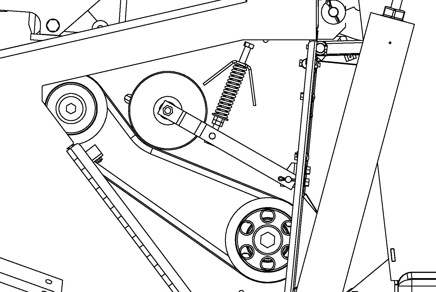
CONDITIONER ROTOR SPEED (Fig. 15)
Conditioning occurs as plants scrape together when accelerating through the conditioning hood. This disturbs the waxy outer layer of the plant stem and speeds up moisture evaporation.
Conditioning intensity can be adjusted by changing the rotor speed. Two rotor speeds are available (850 or 1200 rpm) depending on the position of the drive sheaves 1 and 2. The machine is delivered from the factory on high speed: Small sheave on the rotor and the large sheave on the input drive shaft.
High Speed (1000 rpm) – Ideal for most crops. Low Speed (850 rpm) – Ideal for tender crops or if leaf loss occurs at high speed.
To change rotor speed:
1.Remove rotor drive belt by loosening idler spring until rotor belt can be removed.
NOTE: It may be necessary to remove a sheave in order to remove the belt.
NOTE: The input drive shaft requires two shim washers to properly clamp the sheave. Position the washers on either side of the sheave to properly align the drive sheave with the rotor sheave.

2.Remove cap screws, washers and sheaves 1 and 2.
3.Install sheave removed from the rotor on the input drive shaft. Install sheave removed from the input drive shaft on the rotor. Install washers and cap screws. Tighten cap screws.
4.Install conditioner drive belt and tighten idler spring tension adjustment Nut 3 until the spring length equals 3-1/2″ (89 mm).
5.Tighten Jam Nut 4 securely.
CONDITIONER ROTOR BELT TENSION (Fig. 15)
Conditioner rotor belt tension should be checked weekly and adjusted if necessary. When properly adjusted, the spring length should be 3-1/2″ (89 mm).
1.Loosen jam nut 4.
2.Turn idler spring tension adjustment nut 3 until the spring length equals 3-1/2″ (89 mm).
3.Tighten jam nut 4 securely.
CONDITIONING HOOD ADJUSTMENT (Fig. 16)
A hood is used above the flail conditioner to control, condition and direct the crop toward the rear of the unit. In light crop conditions, the hood can be moved closer to the rotor conditioner to make sure that the flails are making contact with the crop stems. The hood position is controlled with a single lever on the right side of the header behind the access door.

Lower the lever to lower the hood. When the hood is lowered to the lowest position, maximum crop conditioning will occur. Raise the lever to raise the hood for minimum crop conditioning.
WINDROW TO SWATH ADJUSTMENT (Figs. 17 & 18)
The Disc Mower Conditioner will make anything from a narrow windrow to a wide swath, by moving the adjustable deflector up or down. The deflector can be adjusted using the deflector adjustment hand crank. In order to raise the deflector for a narrow windrow, turn the crank clockwise. In order to lower the deflector for a wide swath, turn the crank counterclockwise. Maximum swath width achievable is 100″ (2540 mm). Fine tune windrow width setting by adjusting forming chamber sides. Narrow windrow width is 37″ (940 mm).

Chapter 8 Lubrication
General Information Warning
NEVER lubricate the machine when any part of the unit is in motion. ALWAYS BE SURE to exercise the MANDATORY SAFETY SHUTDOWN PROCEDURE (page 8), BEFORE lubricating the machine.
A sufficient amount of oil or grease will prevent excessive part wear and early failure.
IMPORTANT: Whenever service is performed on hydraulic components (valves, cylinders, hoses, etc.) or Transmissions, care must be taken to prevent discharging fluid onto the ground. Catch and dispose of fluid per local waste disposal regulations.
CUTTERBAR (Fig. 19)

IMPORTANT: The oil in the Cutterbar MUST be changed after the first 10 hours of operation.
It is difficult to accurately check the oil in the cutterbar. If in doubt as to the amount of oil contained in cutterbar, do NOT add oil. Instead, drain and refill the cutterbar. The oil should be changed every 200 hours or at least annually (more often if operated under heavy loads). The cutterbar MUST be drained completely so that the exact volume of oil required can be put back into the cutterbar. The following procedure MUST be followed:
1.Operate the Disc Mower Conditioner for 10 minutes so that the Cutterbar reaches operating temperature.
2.Raise the Disc Mower Conditioner to the transport position and engage the transport lock valves.
3.Park the Disc Mower Conditioner so that the left rear corner of the cutterbar is the lowest point on the cutterbar.
4.Exercise the MANDATORY SAFETY SHUTDOWN PROCEDURE (page 8).
5.Remove the skid shoe from the left end of the Cutterbar. Remove the drain plug from the bottom of the cutterbar and the filler plug located on top, rear of the cutterbar. See Fig. 19. Allow the oil to drain completely. Wait for the dripping to stop.
6.Reinstall the Drain Plug and the Skid Shoe. Refill Cutterbar with 5.25 pt (2.5 L) of SAE #80W90EP gear lube.
The cutterbar should be checked daily for oil drips and dust accumulation around the seals. Oil drips or dust accumulation indicate that the seals are leaking. Oil which is tan in color and foams excessively indicates that it has water present.
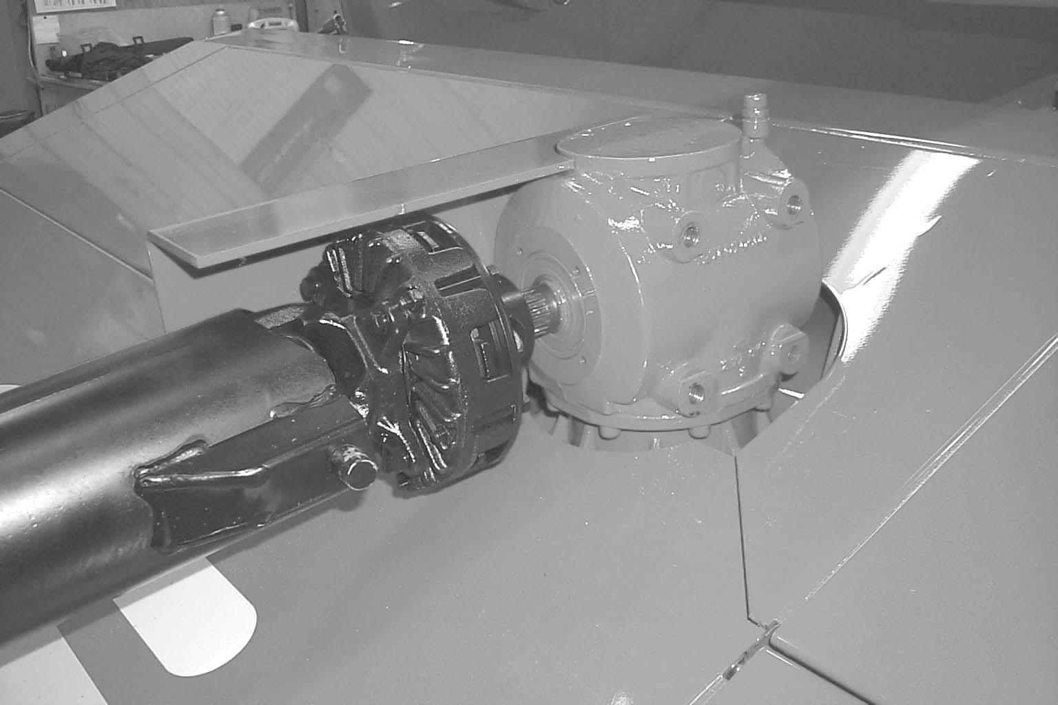
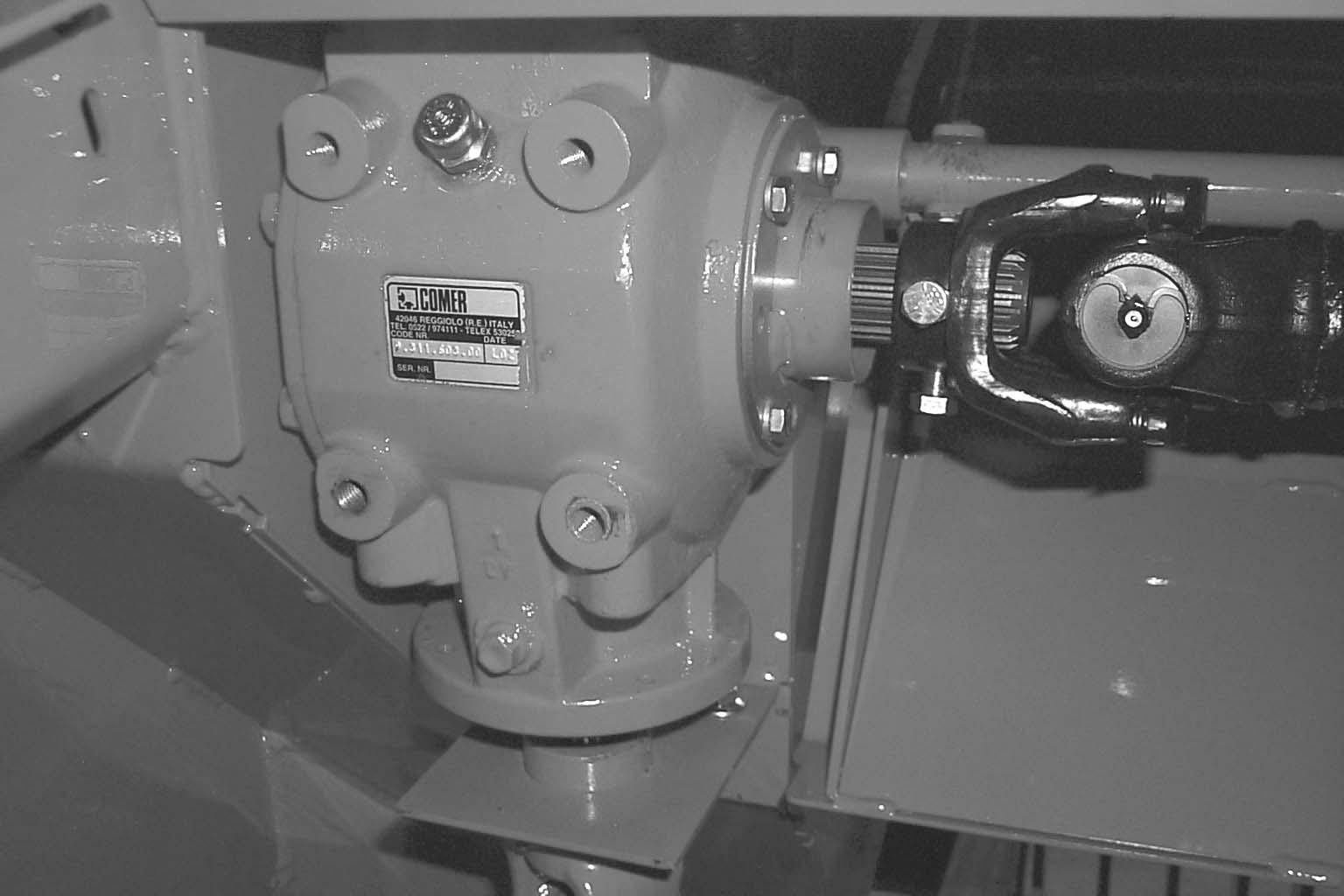
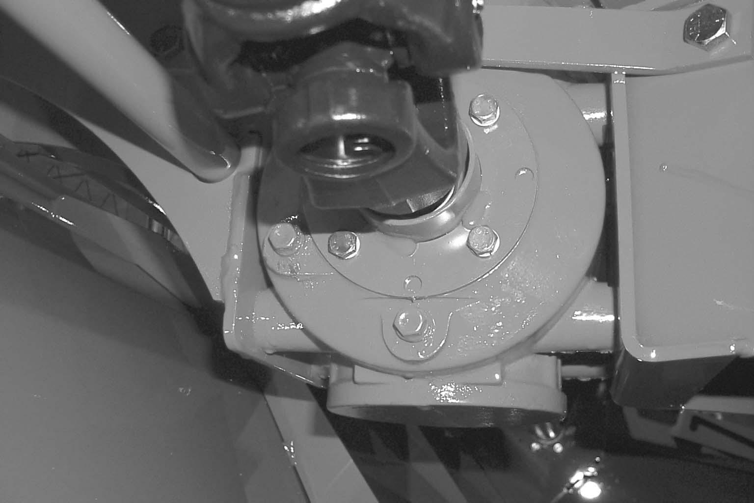
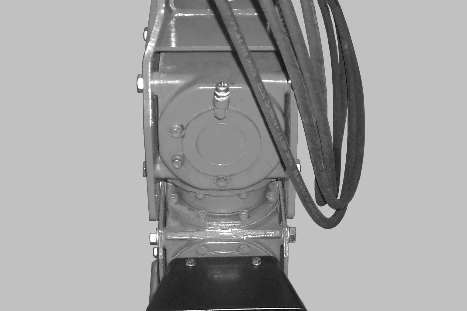
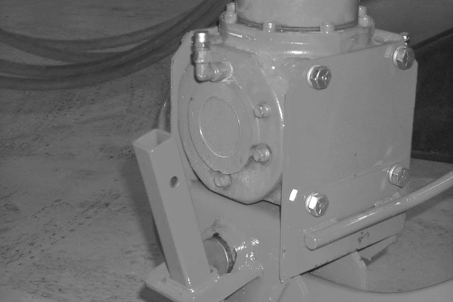
GEARBOXES (3, or 5 with 2-Point Swivel Hitch option) Check Daily (Figs. 20, 21, 22, 23 & 24)
The Disc Mower Conditioner must be down (in a cutting position) before oil levels are checked. Level plugs are provided for checking the oil level in the gearboxes. The correct oil level range is when the oil is up to the level plug with the header down and rotated level (all the way back). The oil should be changed every 200 hours of operation or annually (more often if operated under heavy loads).
The gearboxes use SAE #80W90EP Gear Lube.
Cutterbar Gearbox34 oz. (1.00 L)
Top Header Gearbox29 oz. (0.85 L) . . . . . . . .
Bottom Header Gearbox88 oz. (2.60 L) . . . . .
Swivel Hitch – Top Gearbox37 oz. (1.1 L) . .
Swivel Hitch – Bottom Gearbox56 oz. (1.7 L)
Cutterbar Gearbox
The cutterbar gearbox is located on the right hand side of the unit under the right hand cover. The breather/fill plug is accessible without removing the cover. To gain access to the drain plug, two bolts, lock washers and the cover must be removed. The level plug is accessible by opening the right hand hinged access panel.


Warning
DO NOT operate with the cutterbar gearbox cover removed. Crop will wrap around the gearbox shaft and damage the oil seal resulting in cutterbar gearbox failure.
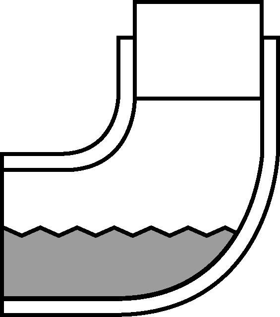
Bottom Header Gearbox
The bottom header gearbox is located in the middle of the unit under the right hand cover. The fill plug is located on the top, rear corner of the bottom header gearbox. The proper oil level will be approximately half–way up the lower portion of the elbow as shown.

Top Header Gearbox
The top header gearbox is located in the middle of the unit. The breather/fill plug, drain plug and level plug are located on the rear of the upper header gearbox.

Top and Bottom Hitch Gearboxes
The top and bottom hitch gearboxes are located on the front of the tongue. The breather/fill plug, drain plug and level plug are located on the rear of the bottom gearbox and on the front of the top gearbox.
The gearboxes should be checked occasionally for oil drips and dust accumulation around the seals. Oil drips or dust accumulation indicate that the Seals are leaking. Oil which is tan in color and foams excessively indicates that it has water present.
NOTE: The oil in the gearboxes MUST be changed after the first 10 hours of operation.
Sealed Bearings
Sealed bearings are used throughout the machine to provide trouble-free operation, with a minimum of maintenance and lubrication. These sealed bearings are lubricated for life and re-lubrication is NOT required, NOR should it be attempted.
Greasing
IMPORTANT: Grease all fittings at the intervals of operation listed, before and after storing the unit, and as otherwise listed. Use a good grade of lithium base grease.
Wipe dirt from the fittings before greasing to prevent any dirt from being forced into the bearings or pivots. Replace any missing fittings. To minimize dirt build-up, avoid excessive greasing.
NOTE: In addition to the fittings, inspect and repack the wheel bearings at least once a season.
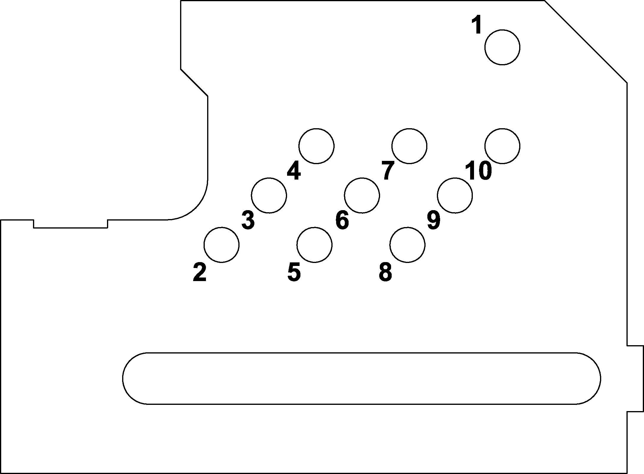
Grease Fitting Locations
Grease Every 10 hours (or Daily)
1.Telescoping PTO Drive Crosses (as many as 11 Places)
2.Telescoping PTO Drive Tube (2 Places)
3.Overrunning Clutch (1 Place)
4.Inner Left Pusharm (2 Places)
5.Inner Right Pusharm (2 Places)
6.Right and Left Wheel Leg Pivots (2 Places)
7.Cutterbar U-joints and spline (3 Places)
Grease Every 50 hours (or Weekly)
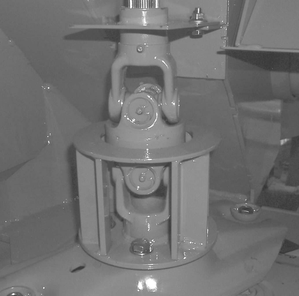
8.Hitch Center Pivot (1 Place)
9.Cross Shaft Spline and Cross (5 Places)
10.Conditioning Hood Pivots (3 Places)
11.Swath Board Adjustment Threads
12.Swivel Gearbox Hitch Pivot (1 Place) (2-point hitch only)
NOTE: To grease the rear telescoping drive Tube (Step 2.), swing the header fully left or right and locate the hole in the inner shield tube. Align the hole with the slot in the outer tube and swing the header until the slot and hole are aligned. Rotate the driveline by hand until the grease fitting lines up with the hole.