10 minute read
CHAPTER 9 SERVICE

General Information Warning
BEFORE servicing this unit, exercise the MANDATORY SAFETY SHUTDOWN PROCEDURE (page 8).
NOTE: The following information is also referred to in the Troubleshooting chapter of this manual. It should be understood that all services detailed in this chapter are owner-operator responsibilities. Certain service routines, where indicated, should only be performed by (or under the direction of) an authorized GEHL equipment dealer.
SEALED BALL BEARING REPLACEMENT (Fig. 25)
Sealed ball bearings are used on various shafts, around the unit. This type of bearing is generally retained, in place, with a self-locking eccentric collar. The lock collar has a counter bored recess, which is eccentric with the collar bore. This eccentric recess engages or mates with an eccentric end of the bearing inner ring, when the bearing is assembled on the shaft. The bearing is engaged, on the inner ring cam, by the collar. This assembly grips the shaft tightly with a positive binding action that increases with use. The collar set screw provides supplementary locking.
A bearing can be removed from the shaft by unscrewing the set screw, placing a punch in the drift pin hole in the direction opposite shaft rotation, and tapping on the punch in order to loosen the self-locking collar.
Install bearings with self-locking collars in the following manner:
1.Place the bearing and collar on the shaft with the cam surfaces next to each other. Tighten the bolts on the bearing retainers.
2.Mate the cam of the lock collar with the cam of the bearing inner ring.
3.Press the locking collar against the bearing wide inner ring and turn it, in the direction of shaft rotation, until it tightly engages. Tighten the collar further by tapping on a punch inserted in the drift pin hole.
IMPORTANT: Overtightening the collar may result in damage.
4.Last, tighten the set screw in the locking collar.
A – Bearing
B – Set Screw
C – Collar Cam
D – Wide Inner Cam Ring
E – Drift Pin Hole
F – Eccentric Self Locking Collar
Fig. 25
Conditioner
Rotor Belt Tension (Fig. 26)
The conditioner rotor belt idler tension is controlled by an adjustable idler spring. The properly adjusted spring length should be 3-1/2” (89 mm).
1.Loosen jam nut.
2.Adjust idler spring tension adjustment nut until proper spring length is attained.
3.Tighten jam nut securely.
Rotor Belt Replacement (Fig. 26)
1.Loosen idler spring tension until rotor belt can be removed.
NOTE: It may be necessary to remove the rotor drive sheave in order to remove the belt.
2.Install new conditioner drive belt and tighten idler spring tension adjustment Nut 3 until the spring length equals 3-1/2″ (89 mm).
3.Tighten Jam Nut 4 securely.
Cutterbar
All service to the internal parts of the cutterbar MUST be performed by (or under the direction of) an authorized GEHL equipment dealer.
The disc bearing housing assemblies are serviceable as complete units or select individual components. Should this be required, contact your Gehl dealer.
DISCS, KNIVES AND HARDWARE
Discs, knives, bolts and nuts are fabricated from high quality steel and undergo a special heat treatment process to ensure a tough wear resistance and hence a longer life. To avoid creating hazardous out-of-balance forces, ALWAYS replace missing, damaged or worn knives and hardware in pairs!
IMPORTANT: Worn or damaged items MUST be replaced immediately with genuine GEHL service parts, otherwise the warranty is void.
Cutterbar Inspection
The cutterbar should be inspected for damage or wear on a regular basis, such as when turning or replacing knives. Inspect the cutterbar more frequently when operating in known rocky conditions.
1.Inspect the external components for damage paying particular attention to the knives and discs. Broken knives and bent or cracked discs are a result of contact with solid foreign objects, and may indicate a possible internal damage. A disc out of time may also indicate internal damage; the discs are properly timed when they are positioned 90° to each other.
Warning
2 – Small Rotor Drive
3 – Idler Spring Tension Adjustment Nut [Properly Adjusted Spring Length should be 3-1/2” (89 mm)]
Sheave Alignment
The sheaves are aligned at the factory and should NOT need adjustment. If sheaves are not properly aligned, contact your Gehl dealer for proper instructions.
The bottom leading edge of worn discs can become very sharp. Wear gloves to prevent injury.
2.While wearing protective gloves, carefully grab both ends of each disc, and try to “rock” the disc up and down. A small amount of movement is normal. An excessive amount of movement may be the result of a loose spindle nut or could indicate a worn housing or bearings. Disc spindles with excessive disc “rock” should have the disc and spindle nut checked for proper torque.
Knife Hardware (Fig. 27)
If any of the following conditions exist, the knife retaining hardware MUST be replaced. See Fig. 27 for details.
1.When a visible deformation is found.
2.When the locking compound on the bolt threads has worn away or if the locking compound has become inoperative due to contamination by water, oil or dirt.
3.When wear on the bolt head reaches the contact area of the knife.
4.When a wear groove deeper than 1/8″ (3 mm) has formed on the bearing shoulder of the knife bolt.
5.When wear on the nut reaches a depth equal to half the height of the nut.
6.When the retaining hardware has been removed five times.
2.The width of a knife, measured at a distance of 3/8″ (10 mm) away from the edge of the disc, MUST be greater than 3/4 of the original width of the knife. (Fig. 28)
3.The hole in knife for retaining bolt MUST NOT become worn oval by more than 1/16″ (2 mm).
1 – Acceptable Bolt with Locking Compound Intact
2 – Unacceptable Bolt with Wear Groove
3 – Unacceptable Bolt with Edge Wear
4 – Acceptable Nut
5 – Unacceptable Nut with Edge Wear
Fig. 27
Removal & Replacement of Blades (Fig. 28)

Knives should be inspected systematically each time before the Disc Mower Conditioner is operated. Failure to replace knives as required will result in an increase in the risk of accidents, a deterioration in the quality of cut and a risk of damage to the cutterbar. both knives on each disc MUST be replaced in pairs to maintain balance if any of the following conditions exist (Fig. 28):
1.If any sign of cracking is found.
A – 3/8″ (10 mm)
B – MUST Be Greater Than 3/4 Width of Knife Here
C – Maximum Out-of-Round 1/16″ (2 mm)
Fig. 28
When replacing knives on the Disc Mower Conditioner, the following steps MUST be followed:
1.Clean around each nut to be removed.
2.Place a block of wood between the discs so the discs will NOT rotate when removing the bolts.
3.Remove nuts with an 6-point, 3/4” socket. Position disc to allow blade bolt to drop through access hole in front center of skid shoe.
4.Clean the hole before installing new blade.
5.Fit new knives or turn knives to use second cutting edge. BE SURE that each knife is positioned with the small arrow pointing in the direction of rotation of the disc that the knife is to be fitted to.
6.MAKE SURE the bolt is in good condition BEFORE reusing.
7.Torque nuts to 90 ft-lbs. (122 N⋅m).
Warning
Use ONLY genuine GEHL service parts.
NOTE: To ensure proper knife retention, the retaining hardware MUST be replaced after having been removed five times.
Warning
ALWAYS replaces damaged knives in pairs. NEVER attempt to straighten a bent knife.
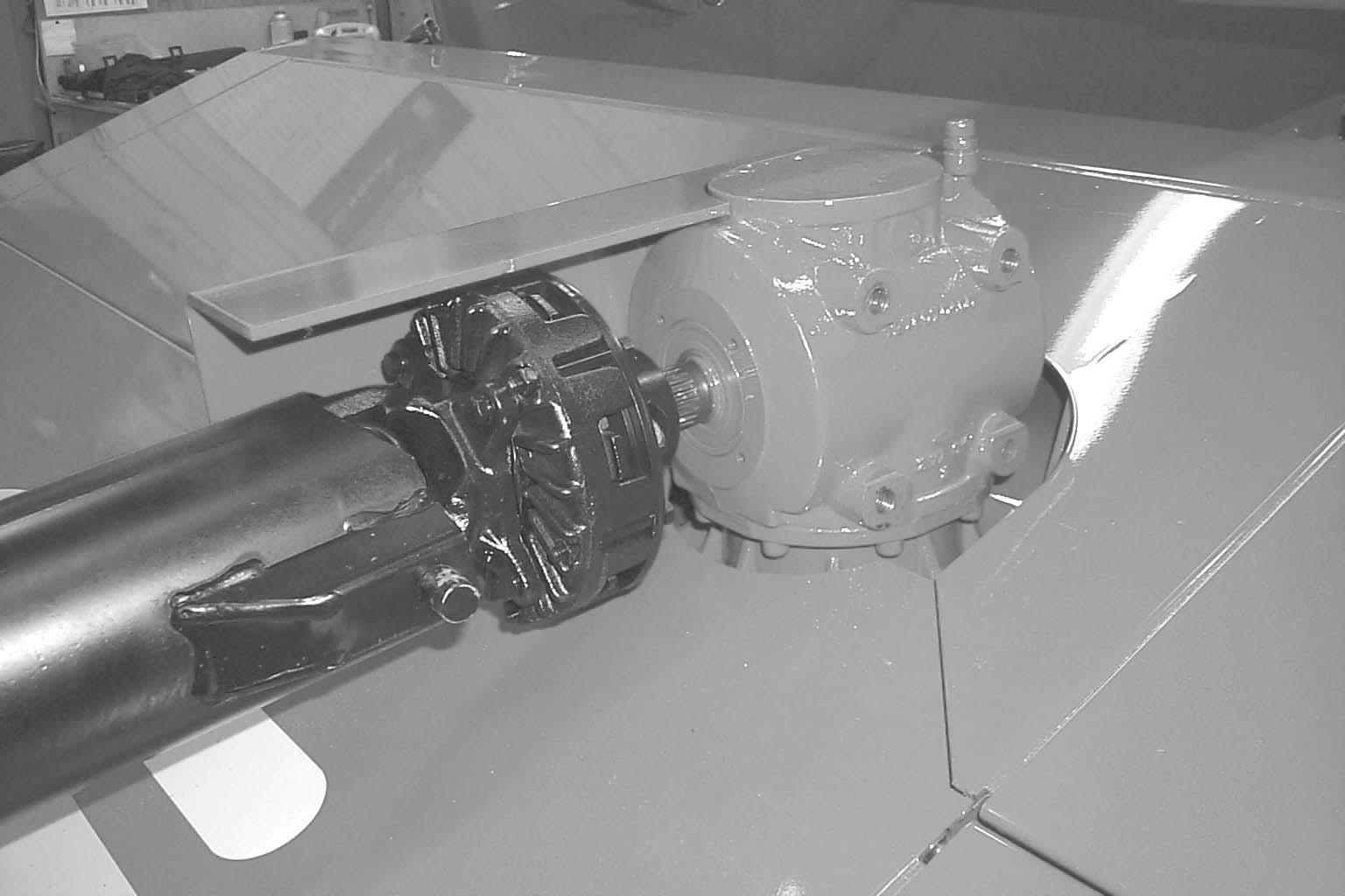
Disc Bearing Housing Removal and Replacement (Fig. 29)


The gear, shaft, bearing, housing and hub that drive the discs are available as complete assemblies. The drive spindle assembly has a machined groove on the outside of the drive flange as shown. The non-drive spindle does not have any markings. When replacing components of these assemblies, make sure to apply Loctite 271 to the bottom spindle nut and torque the nut to 285 ft-lbs. (386 N m). When replacing an assembly, apply silicone sealant around bolts and housing and make sure to position the spindle properly to its adjacent spindles and apply Loctite to nuts and torque to 60 ft-lbs. (81 N⋅m) in a cross-corner pattern. See Fig. 29.
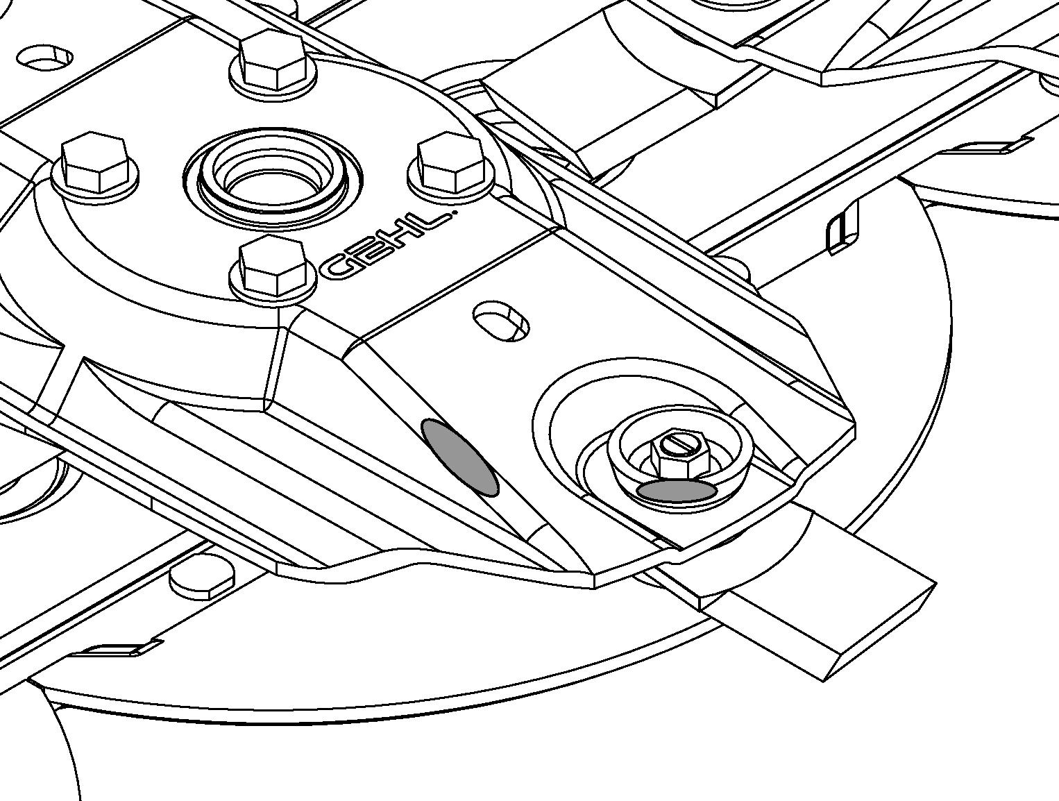
Disc Removal & Replacement (Figs. 30 & 31)
1.Place a block of wood between the discs so the discs will NOT rotate when removing the bolts.
2.Remove the bolts and flat washers.
Fig. 30
Fig. 31
3.Remove the disc. If the disc is tight, pry up with two levers at opposite sides of the disc.
4.Replace the disc MAKING SURE that it is rotated 90° from the next disc and that each blade is positioned with the small arrow pointing in the direction of rotation of the disc. Refer to the Service Parts Manual for the proper positioning of discs. Secure with the bolts and flat washers. Torque to 60 ft-lbs. (81 N⋅m).
NOTE: Disc assemblies must have a minimum clearance of .040″ (1 mm) between the bottom of the knife bolt and the top of the cutterbar and skid shoes. See Figure 31 for details.
NOTE: If a disc shows signs of wear after a considerable amount of acreage has been cut, it is advisable to replace it. Contact your dealer’s Service Department for assistance if the disc assembly-to-cutterbar clearance is less than specified.
Extending Disc Life (Fig. 32)
Under certain conditions, when mowing in abrasive soils, the disc can wear to the point of perforation. If unusual wear is detected prior to perforation as shown in Fig. 32, discs may be moved to a cutting station that rotates in an opposite direction. Proceed as follows:
1.Remove disc according to “Disc Removal & Replacement” topic of this chapter. Remove knives from disc.
2.Locate cutting station that rotates in opposite direction.
3.Install disc according to “Disc Removal & Replacement” topic of this chapter. Install new knives BEING SURE that each knife is positioned with the small arrow pointing in the direction of rotation.
IMPORTANT: If the disc is worn to the point of perforation, the disc MUST be replaced. DO NOT make weld repairs to the discs, as this will affect disc strength and balance.
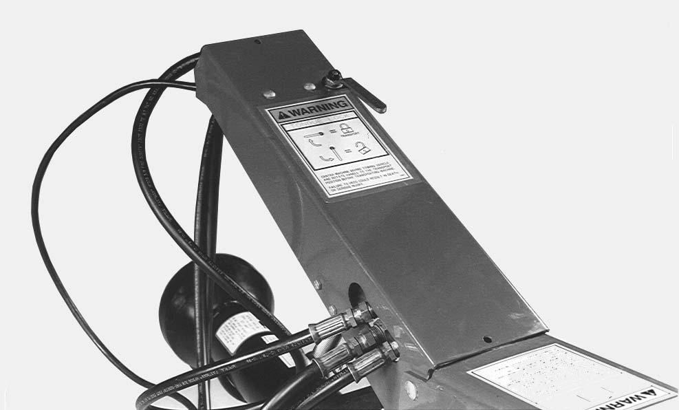
Hydraulic Tongue Cylinder Warning
Do NOT remove hydraulic tongue control cylinder with conditioner header off the ground. The tongue can rotate and cause crush injury.
HYDRAULIC LIFT CYLINDERS (Fig. 33)
IMPORTANT: Whenever service is performed on hydraulic components (valves, cylinders, hoses, etc.), care must be taken to prevent discharging fluid onto the ground. Catch and dispose of fluid per local waste disposal regulations.
The Disc Mower Conditioner lift system consists of a “master-slave” cylinder arrangement, as shown. With a “master-slave” set-up, the hydraulic oil, from the rod end of the master cylinder, goes into the base end of the slave cylinder. Because of this arrangement, both cylinders will extend equally, under any load.
With a “master-slave” arrangement, the cylinders can become out-of-phas such that the machine will raise unevenly (left end higher or lower than the right end). Use the following steps to re-phase the lift cylinders:
1.Completely raise and lower the unit several times, keeping the tractor hydraulic lever engaged, until NO cylinder movement is observed.
NOTE: The cylinders will move very slowly while equalizing.
2.If the unit is still unequal, proceed to step 3 or 4, depending on the problem.
Warning
BE SURE there is NO pressure in the lines when loosening the fittings. Hydraulic fluid, under pressure, can penetrate the skin. If injured by escaping fluid, see a doctor at once. Injected fluid MUST BE surgically removed by a doctor familiar with this type of injury or gangrene may result.
3.If the slave cylinder (right) will NOT raise fully, when the master cylinder (left) is fully raised, loosen the fitting into the slave cylinder (bleed point as shown). With the fitting loose, slowly raise the unit, until oil appears at the fitting. Then, re-tighten the fitting and repeat step 1.
4.If the master cylinder (left) will NOT raise fully, when the slave cylinder (right) is fully raised, loosen the fitting into the slave cylinder (bleed point as shown). With the fitting loose, remove approximately 4 oz (120 cc) of oil for every one inch (25 mm) of cylinder length difference. Then, re-tighten the fitting and repeat step 1.
If the hydraulic cylinders become un-phased frequently during use, it will be necessary to replace the piston seals in the master cylinder. Only replace the slave gland seals if it is leaking externally.
NOTE: A leaking tractor valve may cause one or both hydraulic cylinders to raise slowly while cutting.
Telescoping Drives
IMPORTANT: For safety reasons, service on the telescoping PTO Drives should ONLY be performed by (or under the direction of) an authorized GEHL equipment dealer.
Over time, the telescoping drive universal joints may become worn and noisy and require service. As necessary, remove the drive(s) from the Disc Mower Conditioner and take them to your dealer.
TIRES & WHEELS
Tires should be inflated to 30 PSI (210 kPa). The wheel lug nuts should be torqued to 90 ft-lbs. (124 N m). The wheel bearings should be torqued to 8 ft-lbs. (11 N m), while oscillating the wheel 90°. Then, back off and retorque to 4 ft-lbs. (5 N⋅m). The slotted nuts should be backed off one cotter pin slot.
Check the tire pressures after every 50 hours of operation. Tires should be inflated to 30 PSI (210 kPa). Wheel lug torque should be checked after every 50 hours of operation and tightened to 90 ft lb (124 N m) torque.
Caution
Gehl Company does not sell replacement Tires. In addition, tire mounting, repair and replacements should ONLY be attempted by a qualified tire manufacturer’s representative or by properly trained personnel following the tire manufacturer’s instruction. If you do not have such instructions, contact your tire dealer or Gehl Company.
Warning
Inflating or servicing tires can be dangerous. Whenever possible, trained personnel should be called to service and/or mount tires. In any event, to avoid possible death or serious injury, follow the safety precautions below:
• BE SURE the rim is clean and free of rust.
• Lubricate both the tire beads and rim flanges with a soap solution. Do NOT use oil or grease.
• Use a clip-on tire chuck with a remote hose and gauge which allows you to stand clear of the tire while inflating it.
• DO NOT place your fingers on the tire bead or rim during inflation.
• NEVER inflate beyond 35 PSI (240 kPa) to seat the beads. If the beads have NOT seated by the time the pressure reaches 35 PSI, deflate the assembly, reposition the tire on the rim, relubricate both parts and re-inflate it. Inflation pressure beyond 35 PSI with unseated beads may break the bead or rim with explosive force sufficient to cause death or serious injury.
• After seating the beads, adjust the inflation pressure to the recommended operating pressure listed.
• Do NOT weld, braze, or otherwise attempt to repair or use a damaged rim.