2 minute read
PWP SYSTEM OPERATIONAL TROUBLESHOOTING

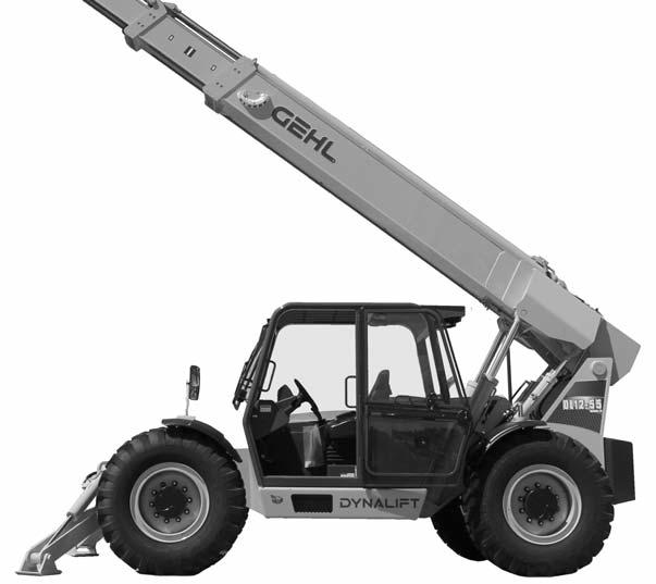
from Gehl DL SERIES GEN2 Dynalift DL7 DL9 DL11 DL12 Telescopic Handler Operator's Manual 50960102 - PDF
Problem
PWP System switch lamp flashes when switch is pressed to “ON.”
Parking brake did not engage when PWP System switch was pressed to “ON.”
Carriage tilt and auxiliary functions continue operating when the PWP System switch is pressed to “ON.”
Transmission does not remain de-clutched when shifted into “Forward” or “Reverse” when the PWP switch is “ON.”
Possible Cause
Remedy
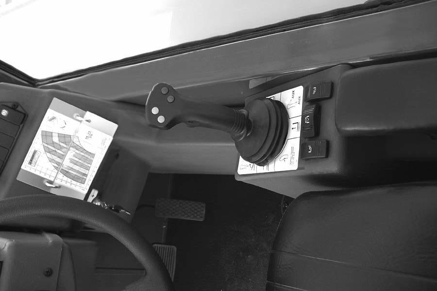
Boom control functions do not operate.
PWP System is not activated.
With PWP System switch “ON,” apply service brakes for three seconds until PWP switch lamp is lit continuously.
PWP System switch lamp flashes when switch is turned “OFF.”
Parking brake switch lamp stays “ON” when PWP System switch is “OFF.”
Machine is not level.
PWP System remote shutdown switch is disengaged.
40’ and 44’ models: PWP System remote shutdown switch is not plugged into the connector at the end of the boom.
55’ model: Low or dead batteries in PWP System remote shutdown switch.
PWP System level sensor unplugged or faulty.
Level the machine.
Engage the PWP System remote shutdown switch.
Plug in and engage the PWP System remote shutdown switch. Replace batteries and engage the PWP System remote shutdown switch.
Contact your Gehl dealer for assistance.
PWP System is not de-activated.
With engine running, apply service brakes for three seconds until PWP switch lamp goes off.
Chapter 9
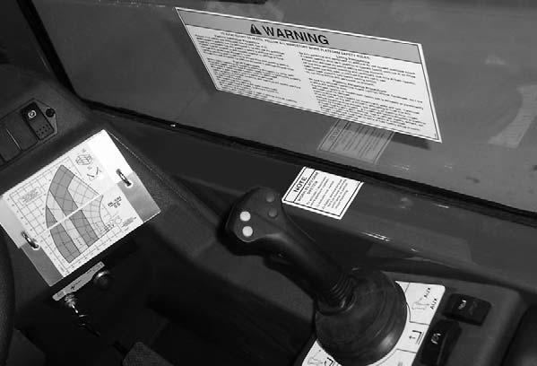
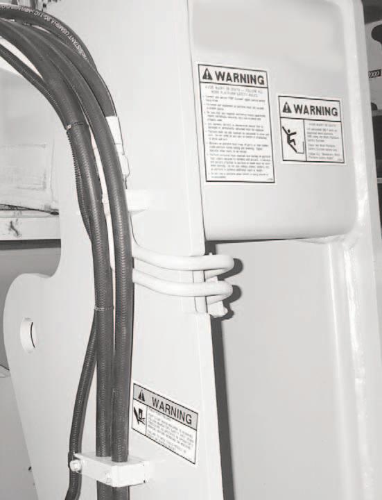
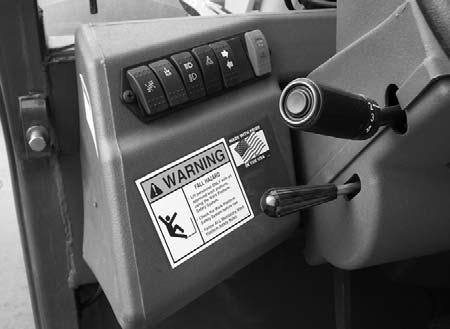
Decal Locations
General Information
Caution
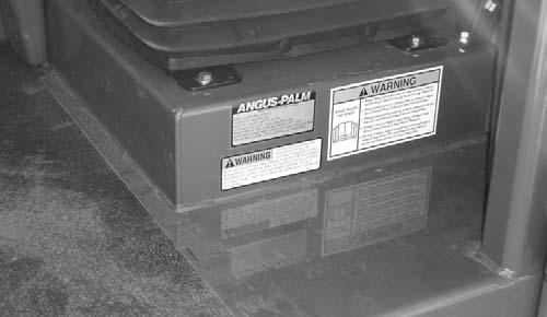
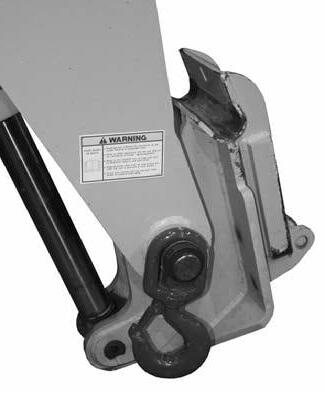
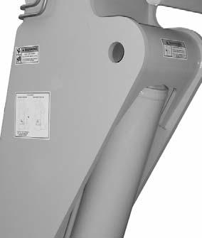
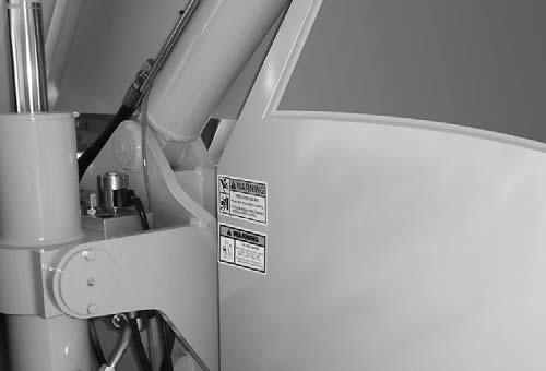
ALWAYS read and follow the safety precautions and information shown on decals. If any decals are damaged or unreadable, or if the unit is repainted, the decals must be replaced. If repainting, BE SURE that all decals that apply to your machine are affixed in their proper locations.
Decal locations information is provided to assist in the proper selection and application of new decals, in the event the original decal become damaged or the machine is repainted.
For correct replacement of decals, compare the location photographs to the machine before starting to refinish the unit. Check off each required decal using the illustration reference number to find the part number, description and quantity in the list. Refer to the appropriate illustration for replacement location.
If there is a decal on a part that is being replaced, be sure that the decal is applied to the replacement part.
NOTE: Refer to the SAFETY chapter of this manual for the specific information provided on the various safety decals.

New Decal Application
Before applying the new decals, surfaces must be free from dirt, dust, grease and other foreign material. To apply a solid-formed decal, remove the smaller portion of the decal backing paper and apply this part of the exposed adhesive backing to the clean surface while maintaining proper position and alignment. Slowly peel off the other portion of the backing paper while applying hand pressure to smooth out decal surface. To apply a pre-mask decal, first remove the backing paper to expose the adhesive side of the decal. Then, properly orient and position the decal onto the clean mounting surface. After the decal is firmly applied and smoothly pressed down, peel off the top covering paper.
Paint Finish
Use this list to order paint for refinishing:
167788One Gal. Yellow
1677896 (12-oz. Spray Cans) Yellow
167754One Gal. Gun-Metal Gray
1677556 (12-oz. Spray Can) Gun-Metal Gray
Decal Kits
50221040Decal Kit, DL7 GEN2 w/o PWP
50221041Decal Kit, DL7 GEN2 w/ PWP
50221042Decal Kit, DL9 GEN2 w/o PWP
50221043Decal Kit, DL9 GEN2 w/ PWP
50221044Decal Kit, DL11-44 GEN2 w/o PWP
50221045Decal Kit, DL11-44 GEN2 w/ PWP
50221046Decal Kit, DL11-55 GEN2 w/o PWP
50221047Decal Kit, DL11-55 GEN2 w/ PWP
50221048Decal Kit, DL12-40 GEN2 w/o PWP
50221049Decal Kit, DL12-40 GEN2 w/ PWP
50221050Decal Kit, DL12-55 GEN2 w/o PWP
50221051Decal Kit, DL12-55 GEN2 w/ PWP
NOTE: Decals may be purchased in kits or individually.
NOTE: Decal kits contain decals for both control configuration. Refer to the following reference pages to determine the correct control decals for the machine.
Note: See Load Zone Charts section of this manual for individual load zone chart part numbers.


DECAL LOCATIONS - PWP EQUIPPED UNITS

REF.DESCRIPTIONDL7DL9DL11DL12
2PERSONNEL
4PERSONNEL
5PWP LOAD ZONE CHARTSee NoteSee NoteSee NoteSee Note 6PWP SYSTEM103028103028103028103028
Note: See Load Zone Charts section of this manual for individual PWP load zone chart part numbers.