27 minute read
A-DAILYOR EVERY10 HOURS OF SERVICE


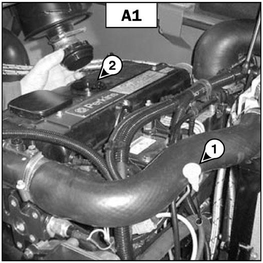
A1 -ENGINE OILLEVEL CHECK
Park the telescopic handler on level ground with the engine stopped, and let the oil drain into the oil pan.
-Open the engine cover.
-Remove the dipstick (1) (fig. A1).
-Wipe the dipstick and check for the correct level at the upper mark.
-If necessary, add oil (see chapter: 6MAINTENANCE: LUBRICANTS AND FUEL) at the filler port (2) (fig. A1).
-Visually check that there is no leakage of oil from the engine.
A2 -ENGINE COOLANT LEVEL CHECK
Park the telescopic handler on level ground with the engine stopped, and allow the engine to cool.
-Open the engine cover.
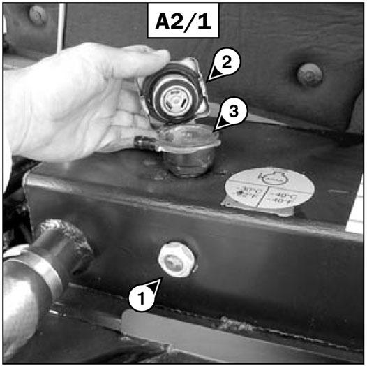
-Check the correct level in the middle of sight gauge (1) (fig. A2/1).
-If necessary, add coolant (see chapter: 6 - MAINTENANCE: LUBRICANTS AND FUEL).
-Slowly turn the cap of the radiator (2) (fig. A2/1) counter-clockwise to the safety stop.
-Allow the pressure and vapor to escape.
-Press down and turn the cap to release the cap.
-Add coolant at the filler neck (3) (fig. A2/1) up to the middle of sight gauge (1) (fig. A2/1).
-Lubricate the filler neck slightly to ease closing and opening of the radiator cap.
-Visually check that there are no leakage from the radiator and hoses.
Warning
To avoid the risk of spraying and scalding, wait until the engine has cooled down before removing the cooling system filler plug. If the coolant is very hot, add only hot coolant 176°F (80°C). In an emergency, you can use water as a coolant, and then change the coolant as soon as possible (see chapter: 6 - MAINTENANCE: F1 - COOLANT).
A3 -FUELLEVEL CHECK
Keep the fuel tank full, to reduce condensation due to atmospheric humidity.
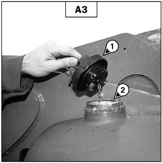
-Remove cap (1) (fig. A3).
-Fill the fuel tank with clean fuel (see chapter: 6MAINTENANCE: LUBRICANTS AND FUEL), filtered through a strainer or a clean, lint-free cloth, through the filler neck (2) (fig. A3).
-Replace the cap (1) (fig. A3).
-Visually check that there is no leakage from the tank and hoses.
Warning
Never smoke or have an open flame nearby during filling operations or when the tank is open.
Never refuel while the engine is running.
IMPORTANT: The fuel tank is vented through the filler cap. When changing it, always use an original part, with a vent.
NOTE: Alocking fuel filler cap is available as an OPTION.
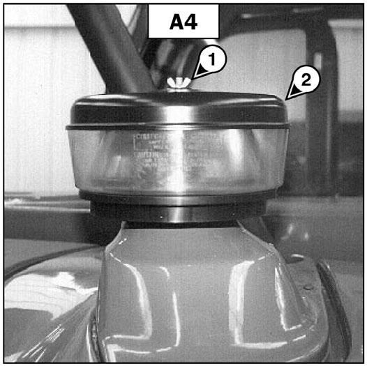
A4 -CYCLONIC PRE-FILTER CLEAN
The cleaning interval is given as a guide; however, the pre-filter must be emptied as soon as impurities reach the MAX level on the collector bowl.
-Loosen nut (1) (fig. A4), remove cover (2) (fig. A4) and empty the collector bowl.
-Visually check that there is no leakage of oil from the transmission.
A6 -TIRE PRESSURES AND WHEEL NUTS TORQUE CHECK
-Check the condition of the tires, to detect cuts, bulges, wear, etc.
-Check the torque of the wheel nuts.
IMPORTANT: Loose wheel nuts can cause damage and failure of the wheel bolts and distortion to the wheels.
Wheel nuts tightening torque:
• Front wheels: 465 ft.-lbs. (630 Nm) ± 15 %
• Rear wheels: 465 ft.-lbs. (630 Nm) ± 15 % Check and adjust the tire pressures if necessary (see chapter: 1 - SPECIFICATIONS).
-Clean the pre-filter unit with a clean dry cloth and reassemble the unit.
IMPORTANT: When cleaning the pre-filter, take care not to let impurities into the dry air filter.
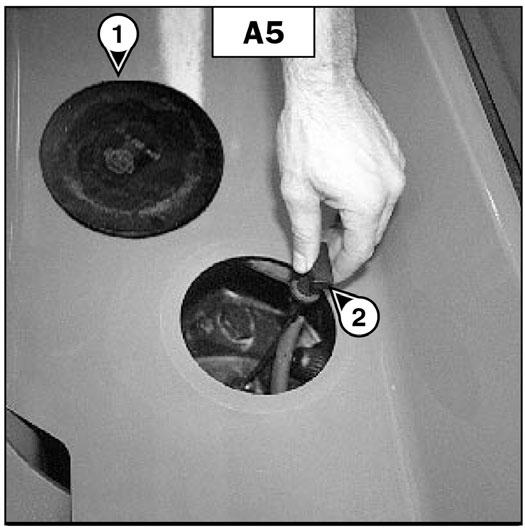
A5 -TRANSMISSION OILLEVEL CHECK
Park the telescopic handler on level ground with the boom raised, the engine stopped and cold. Check the oil level within five minutes of the engine being stopped.
-Remove the plastic cap (1) (fig. A5).
-Remove the dipstick (2) (fig. A5).
Warning
Check that the air hose is correctly connected to the tire valve before inflating. Keep everyone away during inflation. Follow the recommended tire pressures.
Warning
Inflating or servicing tires can be hazardous. Whenever possible, only trained personnel should service and mount tires. To avoid possible death or serious injury, follow the safety precautions below:
1.Be sure the rim is clean and free of rust.
2.Lubricate both the tire beads and rim flanges with a soap solution. DO NOT use oil or grease.
3.DO NOT place your fingers on the tire bead or rim during inflation. Use a clip-on tire chuck with a remote hose and gauge, which allows you to stand clear of the tire while inflating it.
-Wipe the dipstick and check for the correct level between the MIN and MAX marks.
-If necessary, add oil (see chapter: 6 - MAINTENANCE: E3 TRANSMISSION OIL).
4. NEVER inflate beyond 35 psi (240 kPa) to seat the beads. If the beads have not seated by the time the pressure reaches 35 psi (240 kPa), deflate the assembly, reposition the tire on the rim, relubricate both parts and re-inflate. Inflation pressure beyond 35 psi (240 kPa) with unseated beads may break the bead or rim with explosive force sufficient to cause death or serious injury.
5.After seating the beads, adjust the inflation pressure to the recommended operating pressure listed.
6.DO NOT weld, braze, or otherwise attempt to repair and use a damaged rim.
A7 -BOOM WEAR PADS CLEAN - GREASE
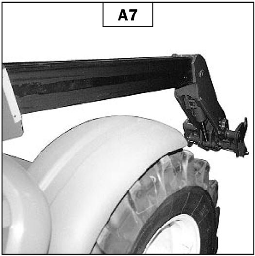
To be carried out every 10 hours during the first 50 hours of service, then once every 250 hours.
-Extend the boom completely.
-With a brush, apply a coat of grease (see chapter: 6 - MAINTENANCE: LUBRICANTS AND FUEL) on the four sides of the telescoping sections (fig. A7).
Warning
Manufacturers of push-pull control cables advise taking the following operation and maintenance precautions:
Do not adjust the control cable with the engine running.
Agradual or sudden increase in the no-load friction (cable disconnected at both ends) of a control cable is an indication of an impending or present performance problem. The control cable should be replaced.
Agradual or sudden decrease in the useable travel is a indication of an impending or present performance problem. The cable should be replaced.
Control cables that have moisture inside of them and/or have frozen should be replaced. Do not apply heat to thaw or dry control cables.
Control cable are lubricated for the life of the control cable. Do not remove the seals or lubricate the control cable.
Control cables are designed to be nonrepairable. Do not attempt to repair control cables.
-Telescope the boom several times in order to spread the grease evenly.
-Remove any excess grease.
IMPORTANT: If the telescopic handler is used in an abrasive environment (dust, sand, coal…), use lubricating oil instead. Consult your dealer.
A8 -GENERALMACHINE OPERATION AND CONDITION CHECK
Are any decals missing or damaged? Are all guards, shields and covers in place? Do all controls function smoothly and properly? Are there any abnormal vibrations or noises? Are any hose or fitting connections leaking? Is the engine exhaust color normal?
Failure to heed could result in death or serious injury.
B -EVERY50 HOURS OF SERVICE
Perform the operations described previously as well as the following operations:
B1 -DRYAIR FILTER CARTRIDGE CHECK - CLEAN
In case of use in a very dusty atmosphere, there are pre-filtration cartridges (see chapter: 6 - MAINTENANCE: FILTER CARTRIDGES AND BELTS). Also, the checking and cleaning period of the cartridge must be reduced.
IMPORTANT: If the clogged filter indicator light comes on, this operation must be carried out as quickly as possible (1 hour maximum). The car- tridge must not be cleaned more than seven times, after which the cartridge must be changed.
-For the disassembly and reassembly of the cartridge, see chapter: 6 - MAINTENANCE: D3DRYAIR FILTER CARTRIDGE.
-Clean the filter cartridge using a compressed air jet (max. pressure 30 psi (2 bar) directed from the top to the bottom and from the inside toward the outside at a minimum distance of 1 inch (25 mm) from the cartridge wall.
-Cleaning is completed when there is no more dust on the cartridge.
IMPORTANT: Keep the safe distance of 1 inch (25 mm) between the air jet and the cartridge to avoid tearing or making a hole in the cartridge. The cartridge must not be blown out near the air filter box. Never clean the cartridge by tapping it against a hard surface. (Protect your eyes during this procedure.)
-Clean the cartridge seal surfaces with a damp, clean lint-free cloth and grease with a silicone lubricant.
-Visually check the outer condition of the air filter and its mounts. Also verify the condition of the hoses and their connections.
IMPORTANT: Do not clean the dry air filter cartridge by washing it. Do not clean the safety cartridge located inside the filter cartridge. Instead, replace it if it is dirty or damaged.
B2 -RADIATOR CLEAN
IMPORTANT: In a dirty atmosphere, clean the radiator every day. Do not use a water jet or highpressure steam, because this could damage the radiator fins.
-Open the engine cover.
-In order to prevent the radiator becoming clogged, clean the radiator with a compressed air jet directed from inside to outside. This is the only way to clean the core of debris.
-If necessary, clean the screen on the engine cover.
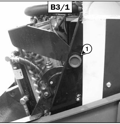
B3 -AIR CONDITIONING CONDENSER CORE CLEAN
IMPORTANT: In a dirty atmosphere, clean the condenser core every day. Do not use a water jet or high-pressure steam, because this could damage the fins.
-Open the engine cover.
-Loosen the knurled screw (1) (fig. B3/1) and swing out the filter and condenser unit.
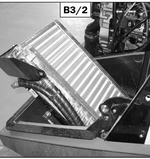
-Clean the core with a blast of compressed air aimed from the inside toward the outside (fig. B3/2). This is the only effective way of cleaning the core.
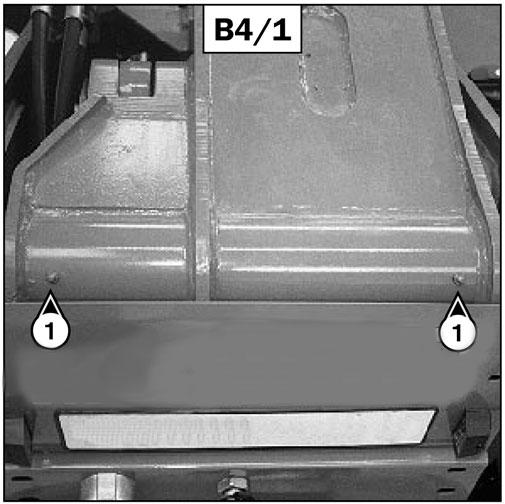
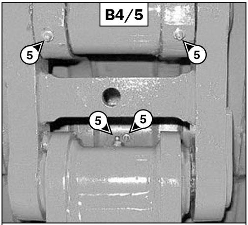
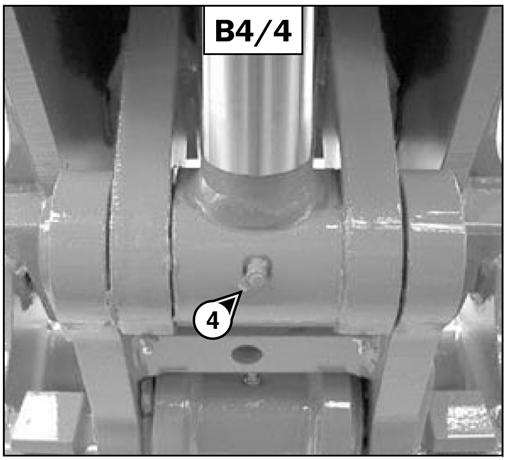
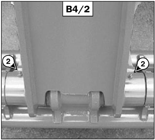
B4 -BOOM GREASE
To be performed weekly, even if the telescopic handler has been operated for less than 50 hours during the week.
IMPORTANT: In the event of prolonged use in an extremely dusty or caustic atmosphere, reduce the service interval to 10 working hours or daily.
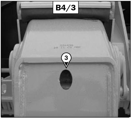
Clean and lubricate the following points with grease (see chapter: 6 - MAINTENANCE: LUBRICANTS AND FUEL). Remove any excess grease.
-Grease fittings for the boom pivot shaft (2) (fig. B4/1).
-Grease fittings of the carriage pivot (2) (fig. B4/2).
-Grease fitting for the tilt cylinder base end (1) (fig. B4/3).
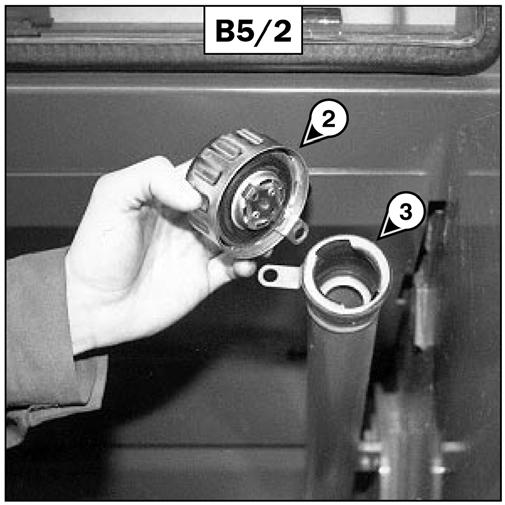
B5 -HYDRAULIC OILLEVEL CHECK
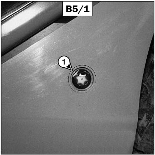
Park the telescopic handler on level ground with the engine stopped, and the boom retracted and lowered as far as possible.
-Refer to sight gauge 1 (fig. B5/1).
-Grease fitting for the tilt cylinder rod end (1) (fig. B4/4).
-The oil level is correct when it is at the level of the red point.
-Grease fittings for the carriage connecting rod shaft (2) (fig. B4/5).
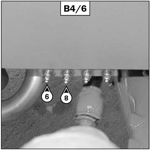
-Grease fitting for the lift cylinder base end (1) (fig. B4/6).
-If necessary, add oil (see chapter: 6 - MAINTENANCE: LUBRICANTS AND FUEL).
-Remove filler cap 2 (fig. B5/2).
-Add oil at filler neck 3 (fig. B5/2).
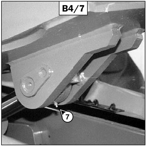
-Grease fitting for the lifting cylinder rod end (1) (fig. B4/7).
-Grease fitting for the slave cylinder base end (1) (fig. B4/6).
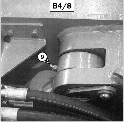
-Grease fitting for the slave cylinder rod end (1) (fig. B4/8).
-Replace the cap.
-Visually check that there is no leakage from the reservoir and pipes.
Always maintain the oil level at the maximum, because cooling depends on oil flowing through the reservoir.
B6 -BRAKE FLUID LEVEL CHECK
Park the telescopic handler on level ground.
- Loosen screw 1 (fig. B6/1) and remove the access panel for the brake fluid reservoir and windshield washer tank 2 (fig. B6/1).

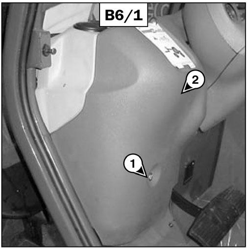
-Visually check the level.
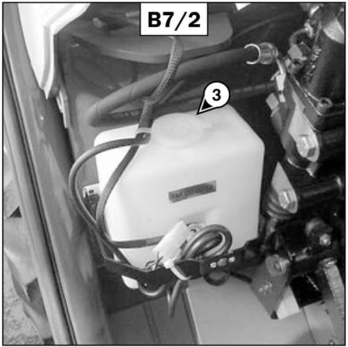
-If necessary, add windshield washer fluid (see: 6MAINTENANCE: LUBRICANTS AND FUEL) at filler neck (3) (fig. B7/2).
B8 - CAB DOOR GREASE
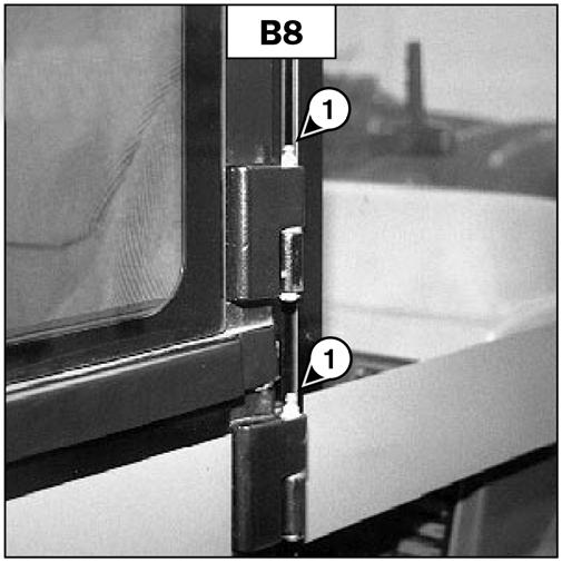
Clean and lubricate the points (1) (4 fittings) (fig. B8) with grease (see chapter: 6 - MAINTENANCE: LUBRICANTS AND FUEL). Remove any excess grease.
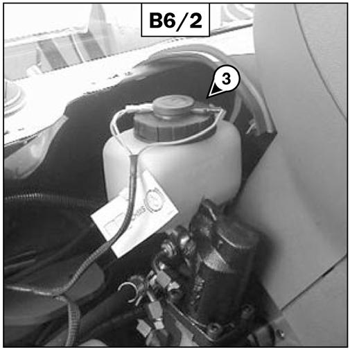
- The level is correct when it is at the MAX level on the reservoir.
-If necessary, add oil (see chapter: 6 - MAINTENANCE: LUBRICANTS AND FUEL) at the filler neck 3 (fig. B6/2).
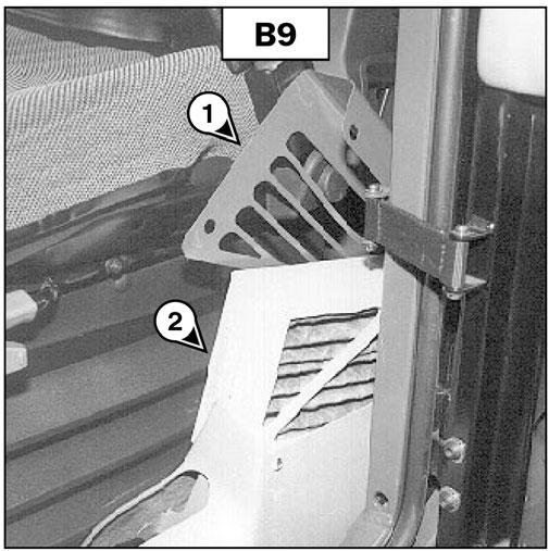
B9 -CAB VENTILATION FILTER CLEAN
-Lift up protective casing (1) (fig. B9).
-Lift out cabin ventilation filter (2) (fig. B9).
-Visually check that there is no leakage at the reservoir and connections.
B7 -WINDSHIELD WASHER FLUID LEVEL CHECK
-Loosen screw (1) (fig. B7/1) and remove the access panel for brake fluid reservoir and windshield washer tank (2) (fig. B7/1).
-Clean the filter with a compressed air jet.
-Check its condition and change if necessary (see: 5 - MAINTENANCE: FILTER CARTRIDGES AND BELTS).
-Reinstall the filter and protective casing.
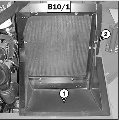
B10 -BATTERYELECTROLYTE LEVEL CHECK
Check the electrolyte level in each cell of the battery. NOTE: If the telescopic handler is working in a high temperature environment, check the level more frequently than every 50 hours of service.
-Open the engine cover.
-Open battery cowl (1) (fig. B10/1) and hold it open with the locking device (2) (fig. B10/1).
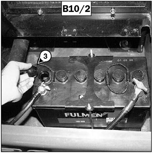
-Remove the caps (3) (fig. B10/2) from each cell of the battery.
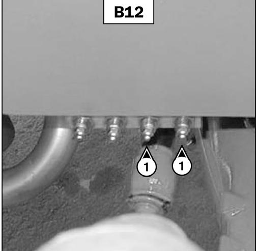
B12 -REAR AXLE OSCILLATION
GREASE
-The level is correct when it is 1/2” (1.3 cm) above the top of the plates in the battery.
-If necessary, top up the cells with clean distilled water that has been stored in a glass container.
-Clean and dry caps (3) (fig. B10/2), and replace and tighten.
-Check the terminal connections and lightly coat them with petroleum jelly to prevent corrosion.
-Close the battery cowl.
Warning
Handling and servicing a battery can be hazarous. Take the following precautions:
-Wear protective goggles.
-Keep the battery horizontal.
-Never smoke or work near an open flame.
-Work in a well-ventilated area.
-In the event of electrolyte being spilled onto the skin or splashed in the eyes, rinse thoroughly with cold water for 15 minutes and call a doctor.
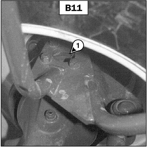
B11 -FRONT AND REAR AXLE SPINDLES
GREASE
Clean and lubricate the points (1) (8 fittings) (fig. B11) with grease (see chapter: 6 - MAINTENANCE: LUBRICANTS AND FUEL). Remove excess grease.
Clean and lubricate the points (1) (2 fittings) (fig. B12) with grease (see chapter: 6 - MAINTENANCE: LUBRICANTS AND FUEL). Remove any excess grease.
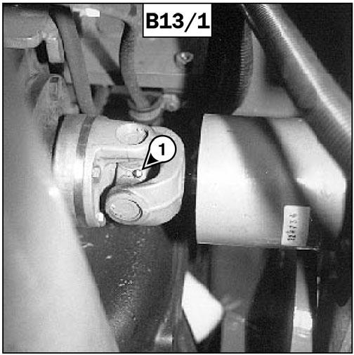
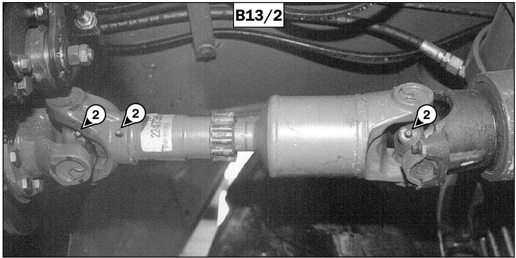
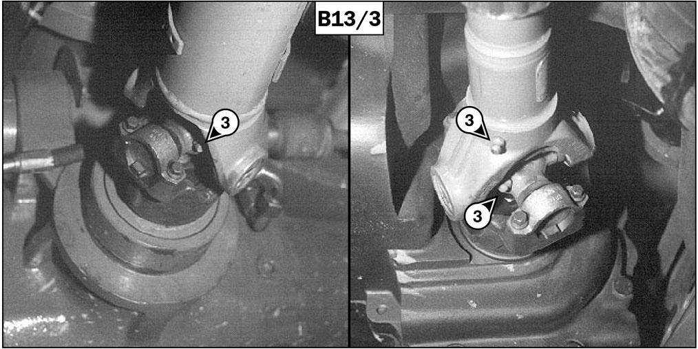
B13 -TRANSMISSION UNIVERSAL JOINTS
GREASE
Clean and lubricate the following points with grease (see chapter: 6 - MAINTENANCE: LUBRICANTS AND FUEL) Remove any excess grease.
1-Grease fittings for the universal joint between engine and angle gear box (2) (fig. B13/1).
2-Grease fittings for the universal joint between the transmission and front axle (3) (fig. B13/2).
C - EVERY250 HOURS OF SERVICE
Perform the operations described previously as well as the following operations:
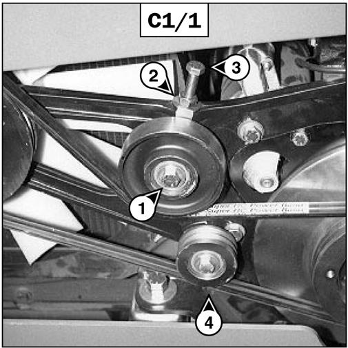
C1 -FANBELT TENSION
CHECK - ADJUST
-Open the engine cover.
-Check the belt for signs of wear and cracks, and change if necessary (see chapter: 6 - MAINTENANCE: FILTER CARTRIDGES AND BELTS).
-Loosen screw (1) (fig. C1/1) on the tension pulley.
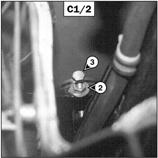
-Loosen lock nut (2) (fig. C1/1 and C1/2) and screw (3) (fig. C1/1 and C1/2).
-Bring the belt just into contact with pulley (4) (Fig. C1/1) (check this operation by feel).
-Mark the head of screw (3) (fig. C1/1 and C1/2) and tighten, turning it five times.
-Tighten the lock nut (2) (fig. C1/1 and C1/2).
-Retighten screw (1) (fig. C1/1) on the tension pulley.
IMPORTANT: When changing the fanbelt, tighten screw (3) (fig. C1/1 and C1/2) one-and-a-half turns, after having allowed the engine to idle for 30 minutes.
C2 -ALTERNATOR/CRANKSHAFT BELT TENSION
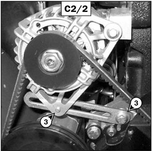
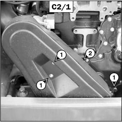
CHECK - ADJUST
-Open the engine cover.
-Loosen the fastening screws (1) (fig. C2/1).
-Remove the protective guard (2) (fig. C2/1).
-Check the belt for signs of wear and cracks, and replace if necessary (see chapter: 6 - MAINTENANCE: FILTER CARTRIDGES AND BELTS).
-Check the belt tension between the pulleys of the crankshaft and the alternator.
-Under normal pressure exerted with the thumb of 10 lbf. (45N), the movement should be approximately 3/8” (10 mm).
-Adjust if necessary: a.Loosen screws (3) (fig. C2/2) two to three turns. b.Pivot the alternator assembly to obtain the belt tension required. c.Retighten screws (3) (fig. C2/2).
-Replace the protective guard (2) (fig. C2/1).
IMPORTANT: If the alternator belt is replaced, check the tension again after 20 hours of operation.
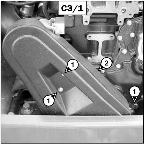
C3 -COMPRESSOR BELT TENSION CHECK - ADJUST
-Open the engine cover.
-Remove the fastening screws (1) (fig. C3/1).
-Remove the guard (2) (fig. C3/1).
-Check the belt for signs of wear and cracks, and replace if necessary (see chapter: 6 - MAINTENANCE: FILTER CARTRIDGES AND BELTS).
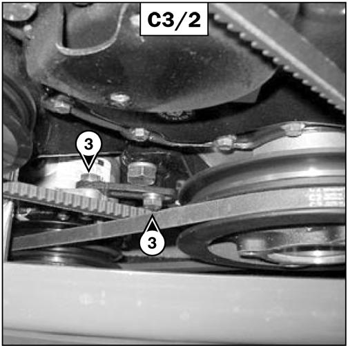
-Check the belt tension between the pulleys of the crankshaft and the compressor.
-Under normal pressure exerted with the thumb of 10 lbf. (45N), the movement should be approximately 3/8” (10 mm).
-Adjust if necessary: a.Loosen screws (3) (fig. C3/2) two to three turns. b.Pivot the compressor assembly to obtain the belt tension required. c.Retighten screws (3) (fig. C3/2).
-Replace the protective guard (2) (fig. C3/1).
-If necessary, add oil (see chapter: 6 - MAINTENANCE: E5 - ANGLE GEAR BOX OIL).
C5 -PARKING BRAKE CHECK - ADJUST
Park the telescopic handler on a slope of less than 15% with the rated load in the transport position.
-Check the tightening adjustment by applying the parking brake to position A(fig. C5).
-The adjustment is correct if the telescopic handler is held stationary on a slope.
-Adjust if necessary.
-Press and release the brake pedal, then release the parking brake, putting it in position B (fig. C5).
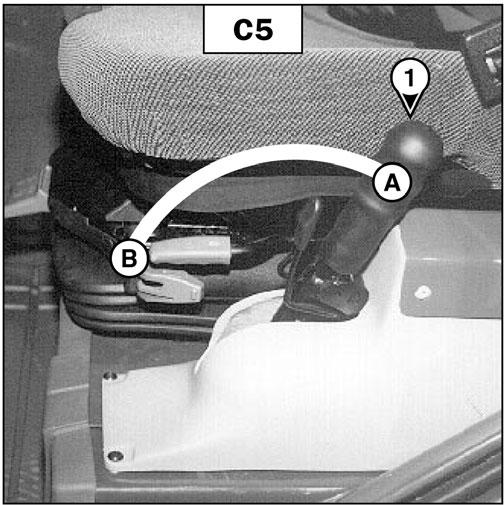
-Progressively tighten the end piece of the lever (1) (fig. C5) and recheck braking adjustment.
-Repeat the operation until the correct braking adjustment is obtained.
C6 -CAB VENTILATION FILTER CHANGE
-Lift up protective casing (1) (fig. C6).
IMPORTANT: If the compressor belt is changed, check the tension again after the first 20 hours of operation.
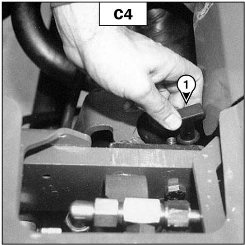
C4 -ANGLE GEAR BOX OILLEVEL CHECK
Park the telescopic handler on level ground with the boom raised and the engine stopped.
-Remove level plug (1) (fig. C4).
-Wipe the dipstick and check for the correct level between the MIN and MAX marks.
-Lift out cabin ventilation filter (2) (fig. C6) and install new replacement filter (see chapter: 6MAINTENANCE: FILTER CARTRIDGES AND BELTS).

-Replace the protective casing.
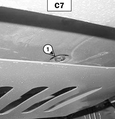
C7 -HEATER CONTROLVALVE CLEAN
-Because the control valve (1) (fig. C7) is located under the cab, it is possible for it to become spattered with mud and obstructed. Clean if necessary.
C8 -FRONT AND REAR AXLE DIFFERENTIALOILLEVEL CHECK
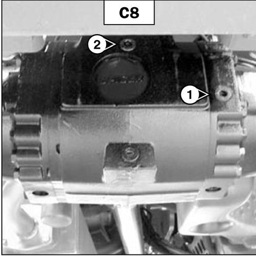
Park the telescopic handler on level ground with the engine stopped.
-Remove level plug (1) (fig. C8). The oil should be flush with the edge of the hole.
-If necessary, add oil
(see chapter: 6MAINTENANCE:
LUBRICANTS AND FUEL) at the filler port (2) (fig. C8).
-Replace and tighten the level plug (1) (fig. C8) [tightening torque: 25 to 36 lbs.-ft. (34 to 49 Nm].
-Repeat the operation for both differentials.
C9 -FRONT AND REAR AXLE PLANETARIES OILLEVEL CHECK
Park the telescopic handler on level ground with the engine stopped.
-Check the level on both front axle planetaries.
-Place level plug (1) (fig. C9) in the horizontal position.
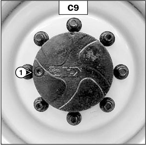
-Remove the level plug; the oil should be flush with the edge of the hole.
-If necessary, add oil (see chapter: 6MAINTENANCE:
LUBRICANTS AND FUEL) through the same hole.
-Replace and tighten the level plug (1) (fig. C9) [tightening torque: 25 to 36 lbs.-ft. (34 to 49 Nm].
-Repeat the operation on both rear axle planetaries.
D -EVERY500 HOURS SERVICE
Perform the operations described previously as well as the following operations.
D1 -ENGINE OIL DRAIN
Park the telescopic handler on level ground, let the engine run at idle for a few minutes, and then stop the engine.
Draining The Oil
-Open the engine cover.
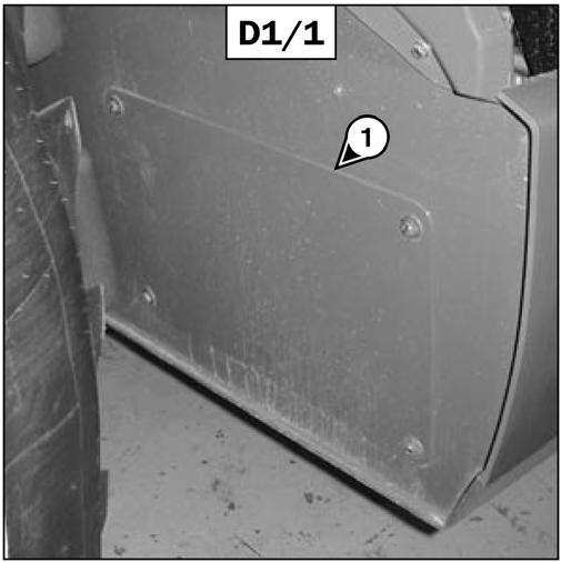
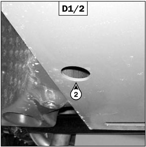
-Remove access panel 1 (fig. D1/1).
-Remove
-Remove properly
IMPORTANT: Dispose of the drain oil in an ecological manner.
D2 -ENGINE OILFILTER CHANGE
Replacing The Filter
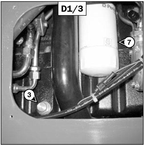
-Remove engine oil filter (7) (fig. D1/3); discard the filter and the filter seal.
-Clean the filter mounting surface with a clean, lintfree cloth.
-Fill the new oil filter (see chapter: 6 - MAINTENANCE: FILTER CARTRIDGES AND BELTS) with engine oil and lightly grease the seal.
-Install the new oil filter.
IMPORTANT: Tighten the oil filter by hand, and then secure the filter with a quarter turn more.
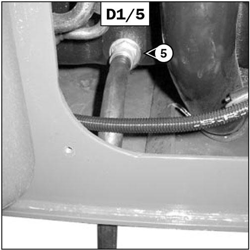
Refilling The Oil
-Loosen, clean and replace the drain hose (4) (fig. D1/4).
-Replace and tighten drain plug (3) (fig. D1/3).
-Replace access panel (1) (fig. D1/1).
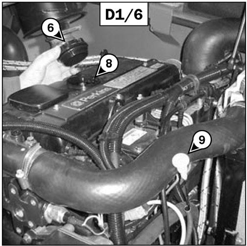
-Fill with oil (see chapter: 6 - MAINTENANCE: LUBRICANTAND FUEL) by filler port (8) (fig. D1/6).
-Wait a few minutes to allow the oil to flow into the crankcase.
-Start the engine and let it run for a few minutes.
-Check for possible leaks at the drain plug and the oil filter.
-Stop the engine, wait a few minutes and check that the level is at the upper mark on dipstick (9) (fig. D1/6).
-Top up if necessary.
D3 -DRYAIR FILTER CARTRIDGE CHANGE
In case of use in a very dusty conditions, the checking and cleaning period of the cartridge must be reduced to 250 hours.
IMPORTANT: Change the cartridge in a clean location, with the engine stopped. Never run the engine with the air filter removed or damaged.
-Open the engine cover.
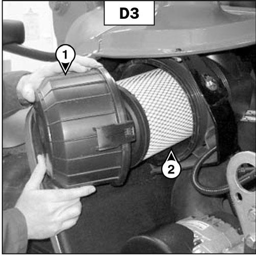
-Loosen the clips and remove cover (1) (fig. D3).
-Gently remove the cartridge (2) (fig. D3), taking care to avoid spilling the dust.
-Leave the safety cartridge in place.
-The following parts must be cleaned with a damp, clean lintfree cloth:
•The inside of the filter and cover.
•The inside of the filter inlet hose.
•The gasket surfaces on the filter and on the cover.
-Check pipes and connections between the air filter and the engine, and the connection and condition of the filter indicator.
-Before installing, check the condition of the new cartridge (see chapter: 6 - MAINTENANCE: FILTER CARTRIDGES AND BELTS).
-Install the cartridge onto the filter axis and push it in, pressing the edges and not the middle.
-Reassemble the cover, with the dust valve downward.
D4 -FUELFILTER CARTRIDGE CHANGE
-Open the engine cover.
-Carefully clean the outside of the filter and its holder, to prevent dust from getting into the fuel system.
Warning
Make sure the electrical system on the telescopic handler is disconnected, otherwise fuel will be released if the fuel pump is on.
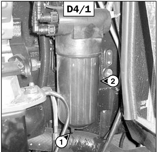
-Place a container under the filter and drain it via drain plug (1) (fig. D4/1).
-Loosen the body of filter (2) (fig. D4/1).
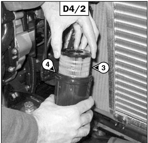
-Remove the filter cartridge by pressing the cartridge (3) (fig. D4/2) down against the pressure of the spring and turning it to the left.
-Insert a new cartridge (see chapter: 6 - MAINTENANCE: FILTER CARTRIDGES AND BELTS), by pressing the cartridge (3) (fig. D4/2) down against the pressure of the spring and turning it to the right to lock it into the body of the filter.
-Place the new seal (4) (fig. D4/2) onto the body of the filter and lubricate the contact surface using clean engine oil.
-Remount the body of the filter onto its holder. Hand-tighten it and then secure it with a quarter turn more.
-Close drain plug (1) (fig. D4/1) and remove the container.
-Before starting the engine, leave the ignition on for one minute, to give the fuel pump time to relieve air from the filter.
-Start the engine and make sure there is no leakage.
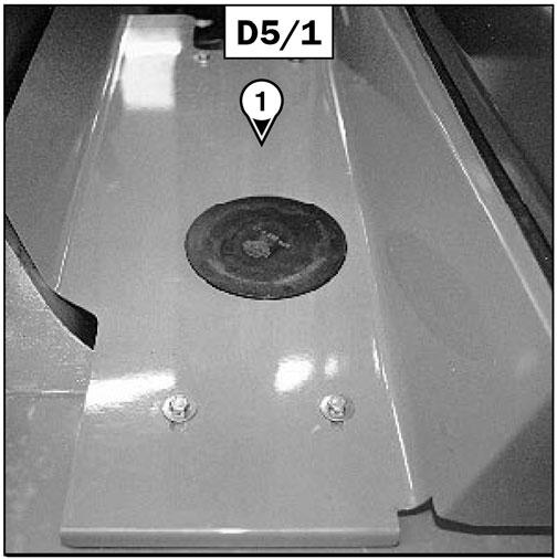
D5 -TRANSMISSION OILFILTER CHANGE
-Remove the cover plate (1) (fig. D5/1).
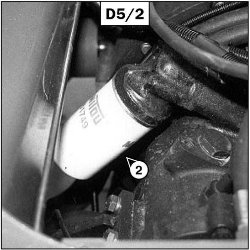
-Remove and discard the transmission oil filter (2) (fig. D5/2).
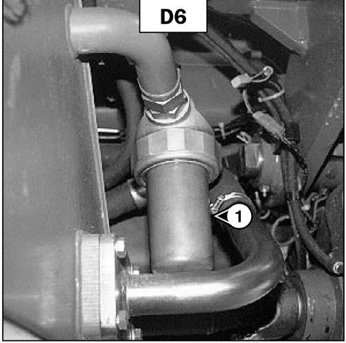
D6 -HYDRAULIC RETURN OILFILTER CARTRIDGE CHANGE
Stop the engine and relieve the pressure from the circuits by cycling the hydraulic controls.
IMPORTANT: Thoroughly clean the outside of the filter and its surroundings before servicing, to prevent contaminating the hydraulic system.
-Place a container under hydraulic filter drain (1) (fig. D6).
-Unscrew the body of the filter.
-Remove the hydraulic return oil filter cartridge and install a new replacement cartridge (see chapter: 6 - MAINTENANCE: FILTER CARTRIDGES AND BELTS).
-Make sure that the cartridge is correctly positioned, and replace the body of the filter.
Warning
Tighten the body of the filter by hand, and then secure the body of the filter with a quarter turn more.
D7 -COUNTER-BALANCE VALVE CHECK
-Carefully clean the filter head with a clean, lintfree cloth.
-Slightly lubricate the new seal and fit the seal on the filter.
-Fill the new transmission oil filter (see chapter: 6MAINTENANCE: FILTER CARTRIDGES AND BELTS) with oil (see chapter: 6 - MAINTENANCE: LUBRICANTS AND FUEL).
-Install the filter, making sure that the seal is correctly positioned and tightened.
IMPORTANT: Tighten the transmission oil filter by hand, and then secure the filter with a quarter turn more.
-Replace the cover plate (1) (fig. D5/1).
To be performed after the first 50 hours of operation and then every 500 hours.
Park the telescopic handler on level ground, apply the parking brake and shift the transmission into neutral.
Warning
Keep everyone well away during these inspections.
In all cases, the counter-balance valve must be repaired or replaced if hydraulic movement continues after the engine has been turned off.
Never use the telescopic handler with a defective counter-balance valve.
PURPOSE OF COUNTER-BALANCE VALVES
-The counter-balance valves protect the user from any risk due to a sudden drop in hydraulic pressure or failed hose.
TESTING EACH HYDRAULIC CIRCUIT
LIFTING CIRCUIT:
-Start the telescopic handler and raise the boom to about 45°.
-With the engine running at mid-speed, lower the boom. While the boom is lowering, turn off the engine. Movement should slow as the engine speed falls and stop when the engine stops.
TELESCOPING CIRCUIT:
-Start the telescopic handler and raise the boom as far as it will go, and extend the telescopic section completely.
-With the engine running at mid-speed, retract the boom. When retracting the boom, turn off the engine. Movement should slow as the engine speed falls and stop when the engine stops.
TILTCIRCUIT:
-Place a nominal load on the forks, and anchor it securely to prevent it from falling off during the test.
-Start the telescopic handler and tilt the carriage rearward, lifting the boom sufficiently to allow the carriage to tilt.
-With the engine running at mid-speed, tilt the carriage forward. While it is tilting, turn off the engine. Movement should slow down as the engine speed falls and stop when the engine stops.
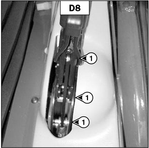
D8 -PARKING BRAKE LEVER MECHANISM
Grease
-Clean and lubricate pivot pins (1) (fig. D8) with oil (see chapter: 6 - MAINTENANCE: LUBRICANTS AND FUEL).
D9 -CAB VENTILATION FILTER CLEAN
-Lift up the protective casing (1) (fig. D9).
-Lift out the cabin ventilation filter (2) (fig. D9).

-Clean the filter with a compressed air jet.
-Check its condition and replace if necessary (see chapter: 6MAINTENANCE: FILTER CARTRIDGES AND BELTS).
-Reinstall the filter and protective casing.
D10 -BATTERYELECTROLYTE
Density Check
The electrolyte density varies depending on the temperature, but a minimum specific gravity of 1.260 at 60°F (16°C) must be maintained. In the shaded area (fig. D10), the battery is in a normal charged condition. Readings above this zone indicate that the battery needs to be recharged.
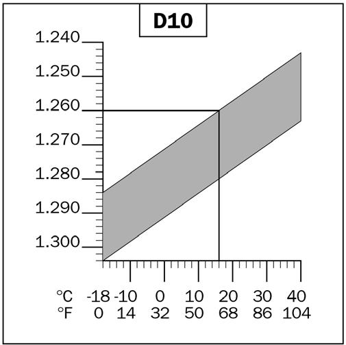
-Check the electrolyte density in each battery cell using a hydrometer. The density should not vary more than 0.025 units between cells.
-Do not perform this check immediately after topping up with distilled water. Recharge the battery for at least an hour before checking the battery electrolyte density.
Warning
Handling and servicing a battery can be hazardous. Take the following precautions:
-Wear protective goggles.
-Keep the battery horizontal.
-Never smoke or work near an open flame.
-Work in a well-ventilated area.
-In the event of electrolyte being spilled onto the skin or splashed in the eyes, rinse thoroughly with cold water for 15 minutes and call a doctor.
D11 -FRONT AND REAR AXLE DIFFERENTIALOIL DRAIN
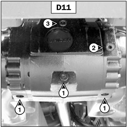
Park the telescopic handler on level ground with the engine stopped and the differential oil still warm.
IMPORTANT: Dispose of the drain oil in an ecological manner.
-Place a container under the drain plugs (1) (fig. D11) and unscrew the plugs.
-Remove level plug (2) (fig. D11) and filler plug (3) (fig. D11) to ensure that the oil drains properly.
-Replace and tighten drain plugs (1) (fig. D11) [tightening torque: 25 to 36 ft.-lbs. (34 to 49 Nm].
-Fill with oil (see chapter: 6 - MAINTENANCE: LUBRICANTS AND FUEL) at filler port (3) (fig. D11).
Park the telescopic handler on level ground with the engine stopped.
-Inspect the fuel system and tank for leaks.
-In the event of a leak, contact your dealer.
Warning
Never weld while alone, because welding can cause an explosion or a fire.
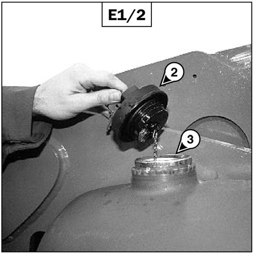
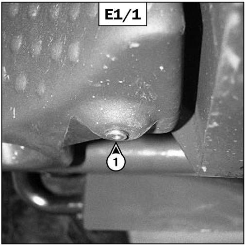
-Place a container under drain plug (1) (fig. E1/1) and unscrew the plug.
-Remove cap (2) (fig. E1/2).
-Drain out 2-1/2 gallons (10 litres) of clean fuel at filler port (3) (fig. E1/2).
-Replace and tighten drain plug (1) (fig. E1/1) [tightening torque: 21 to 29 ft.-lbs. (29 to 39 Nm).]
-Fill the fuel tank with clean fuel (see chapter: 6MAINTENANCE: LUBRICANTS AND FUEL) filtered through a strainer or a clean, lint-free cloth and replace the filler plug (2) (fig. E1/2).
-The level is correct when the oil level is flush with the edge of port (2) (fig. D11).
-Check for any leaks at the drain plugs.
-Replace and tighten level plug (2) (fig. D11) [tightening torque: 25 to 36 ft.-lbs. (34 to 49 Nm] and filler plug (3) (fig. D11) [tightening torque: 25 to 36 ft.-lbs. (34 to 49 Nm].
-Repeat this operation for the rear axle differential.
E - EVERY1000 HOURS OF SERVICE
Perform the operations described previously as well as the following operations:
E1 -FUELTANK
Clean Warning
Do not smoke or work near an open flame while performing these operations.
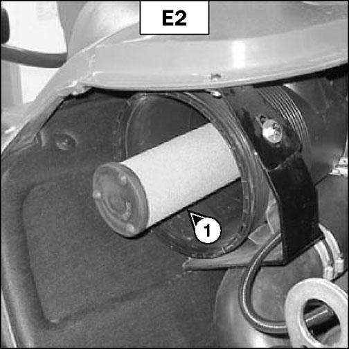
E2 -SAFETYDRYAIR FILTER CARTRIDGE CHANGE
-For the disassembly and reassembly of the cartridge, see chapter: 6 - MAINTENANCE: D3AIR FILTER CARTRIDGE.
-Gently remove the air filter safety cartridge (1) (fig. E2), taking care to avoid spilling the dust.
-Clean the gasket surface on the filter with a damp, clean lint-free cloth.
-Before mounting, check the condition of the new safety cartridge (see chapter: 6 - MAINTENANCE: FILTERS CARTRIDGES AND BELTS).
-Install the cartridge onto the filter axis and push it in, pressing the edges and not the middle.
NOTE: The period for changing the safety cartridge is given for information only. The safety cartridge must be changed after every two changes of the air filter cartridge
E3 -TRANSMISSION OIL
Drain
Park the telescopic handler on level ground with the engine stopped and the transmission oil still warm.
Draining The Oil
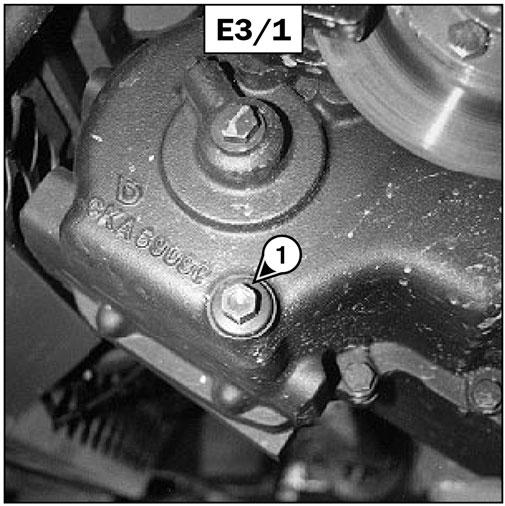
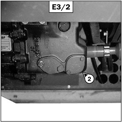
-Place a container under drain plug (1) (fig. E3/1) and under cover (2) (fig. E3/2) and unscrew the drain plug.
E4 -TRANSMISSION HOUSING STRAINER CLEAN CLEANING THE STRAINER
-Remove cover (2) (fig. E3/2) and set aside the oring joint and sealing washer.
-Allow the rest of the oil to drain.
-Remove and clean the strainer using a compressed air jet.
-Clean the magnetic section on the plate.
-Replace the assembly and tighten plate (2) (fig. E3/2) [tightening torque: 13 to 23 ft.-lbs. (18 to 31 Nm)].
Refilling The Oil
-Replace and tighten drain plug (1) (fig. E3/1) [tightening torque: 25 to 40 ft.-lbs. (34 to 54 Nm)].
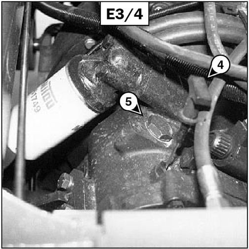
-Fill with oil (see chapter: 6 - MAINTENANCE: LUBRICANTS AND FUEL) at filler port (5) (fig. E3/4) and replace the plug.
-Start the engine and let it run for a few minutes.
-Check for leaks from the drain plug and cover.
-Stop the engine, and within five minutes of the engine being stopped, check on the dipstick (4) (fig. E3/4) for the correct level between the MIN and MAX marks.
-Top up if necessary.
-Replace the cover plate (3) (fig. E3/3).
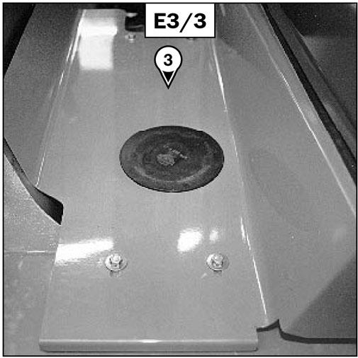
-Remove cover plate (3) (fig. E3/3).
-Remove dipstick (4) (fig. E3/4) and unscrew filler plug (5) (fig. E3/4) to ensure that the oil drains properly.
E5 -ANGLE GEAR BOX OIL
DRAIN
Park the telescopic handler on level ground with the engine stopped and the angle gear box oil still warm.
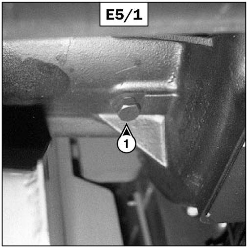
-Place a container under drain plug (1) (fig. E5/1) and unscrew the plug.
IMPORTANT: Dispose of the drain oil in an ecological manner.
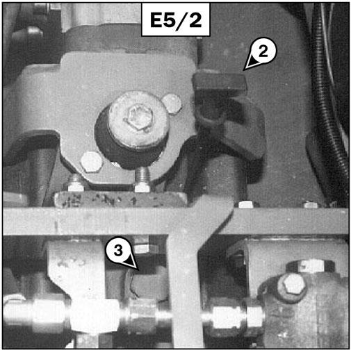
-Remove dipstick (2) (fig. E5/2) and unscrew filler cap (3) (fig. E5/2) to ensure that the oil drains properly.
-Replace and tighten drain plug (1) (fig. E5/1) [tightening torque: 15 to 21 ft.-lbs. (20 to 29 Nm)].
IMPORTANT: Dispose of the drain oil in an ecological manner.
-Fill with oil (see chapter: 6 - MAINTENANCE: LUBRICANTS AND FUEL) at filler port (3) (fig. E5/2) and replace the filler cap.
-Check for the correct level between the MIN and MAX marks on the dipstick (2) (fig. E5/2).
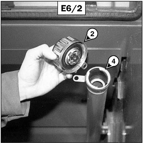
(see chapter: 6 - MAINTENANCE: FILTER CARTRIDGES AND BELTS).
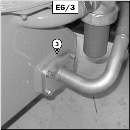
-Replace the strainer and tighten the suction strainer cover (3) (fig. E6/3) [tightening torque: 60 ft.lbs. (81 Nm)] making sure the seal is in the correct position.
-Check for any leaks at the drain plug.
E6 -HYDRAULIC OIL
DRAIN
Park the telescopic handler on level ground with the engine stopped and telescopic boom retracted and lowered as far as possible.
IMPORTANT: Before servicing, thoroughly clean the area surrounding the drain plugs and the suction cover on the hydraulic tank.
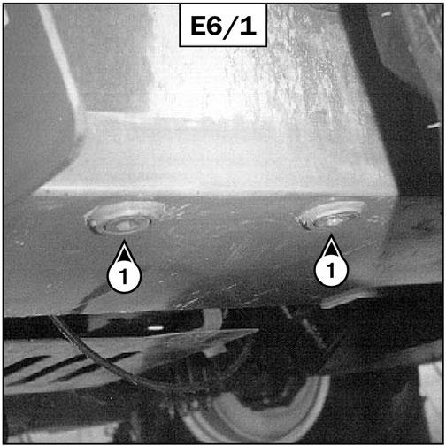
DRAINING THE OIL
-Place a container under drain plug (1) (fig. E6/1) and unscrew the plug.
-Remove filler cap (2) (fig. E6/2) to ensure that the oil drains properly.
E8 -FILTER CAPFOR HYDRAULIC OILTANK CHANGE
FILLING THE OILTANK
-Clean and reinstall the drain plug (1) (fig. E6/1) [tightening torque: 21 to 29 ft.-lbs. (29 to 39 Nm)].
-Fill with oil (see chapter: 6 - MAINTENANCE: LUBRICANTS AND FUEL) at filler port (4) (fig. E6/2).
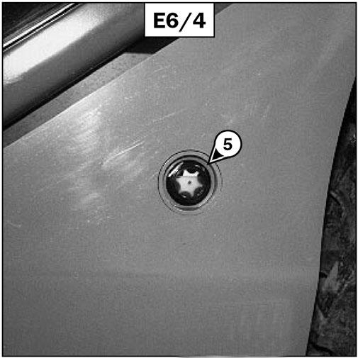
-Observe the oil level on dipstick (5) (fig. E6/4); the oil level should be at the level of the red point.
IMPORTANT: Dispose of the drain oil in an ecological manner.
E7 -SUCTION STRAINER FOR HYDRAULIC OILTANK CLEAN
CLEANING THE STRAINER
-Remove suction strainer cover (3) (fig. E6/3).
-Remove and clean the strainer using a compressed air jet. Check its condition and replace if necessary
-Check for any possible leaks at the drain plug.
-Replace filler plug (2) (fig. E6/2) with a new filler plug (see chapter: 6 - MAINTENANCE: FILTER CARTRIDGES AND BELTS).
E9 -SEAT BELT CHECK
SEATBELTWITH TWO ANCHOR POINTS
-Check the following points:
•Tightness of the anchor points on the seat
•Cleanliness of the belt and the locking mechanism
•Actuation of the locking mechanism
•Condition of the belt (cuts, curled edges)
RETRACTABLE SEATBELTWITH TWO ANCHOR POINTS
•The correct retracting of the belt
•Condition of the reel guards
•Roller locking mechanism when the belt is given a sharp pull
Warning
Under no circumstances should the telescopic handler be used if the seat belt is faulty (not latching, has cuts or tears, etc.). Repair or replace the seat belt immediately.
IMPORTANT: After an accident that involved stressing the seat belt, replace the seat belt.
E10 -FRONT AND REAR AXLE PLANETARIES OIL
DRAIN
Park the telescopic handler on level ground with the engine stopped and the planetaries still warm.
IMPORTANT: Dispose of the drain oil in an ecological manner.
-Drain and change both front axle plantaries:
•Place drain plug (1) (fig. E10) in position A.
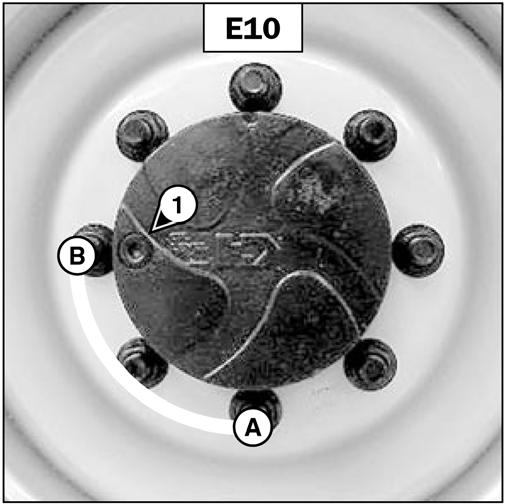
•Place a container under the drain plug and unscrew the plug.
•Let the oil drain fully.
•Place the drain port in position B, i.e., in a level position.
•Fill with oil (see chapter: 6 - MAINTENANCE: LUBRICANTS AND FUEL) by level port (1) (fig. E10).
•The level is correct when the oil level is flush with the edge of the hole.
•Reinstall and tighten the drain plug (1) (fig. E10) [tightening torque: 25 to 36 ft.-lbs. (34 to 49 Nm)].
•Repeat this operation on both rear axle planetaries.
F - EVERY2000 HOURS OF SERVICE
Perform the operations described previously as well as the following operations:
F1 -COOLANT
DRAIN
These operations are to be carried out as necessary, or every two years at the beginning of winter. Park the telescopic handler on level ground with the engine stopped and cold.
DRAINING THE COOLANT
-Open the engine cover.
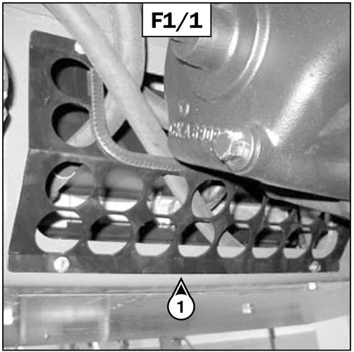
-Remove the shroud (1) (fig. F1/1).
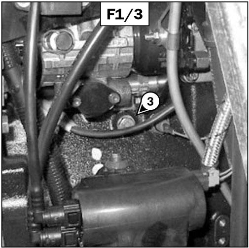
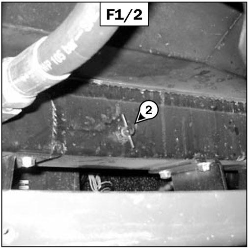
-Set a container under drain valve (2) (fig. F1/2) on the radiator and drain plug (3) (fig. F1/3) of the engine block and loosen them.
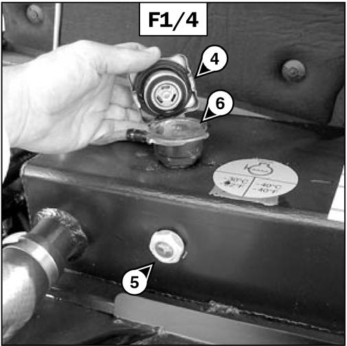
-Remove the radiator filler cap (4) (fig. F1/4).
-Let the coolant drain entirely while ensuring that the ports do not get clogged.
-Check the condition of the hoses as well as the clamping devices and change the hoses if necessary.
-Rinse the cooling system with clean water. Use a cleaning agent if necessary.
REFILLING THE COOLANT
-Tighten the drain valve (2) (fig. F1/2) and drain plug (3) (fig. F1/3) [tightening torque: 30 ft.-lbs. (40 Nm)].
-Slowly fill the cooling system with coolant (see chapter: 6 - MAINTENANCE: LUBRICANTS AND FUEL) to the middle of sight gauge (5) (fig. F1/4) through filler port (6) (fig. F1/4).
-Replace filler cap (4) (fig. F1/4).
-Run the engine at idle for a few minutes.
-Check for any leaks.
-Replace the shroud (1) (fig. F1/1)
-Check the level and refill if necessary.
IMPORTANT: The engine does not contain corrosion protection and must be filled during the entire year with a mixture containing 50% ethylene glycol-based antifreeze.
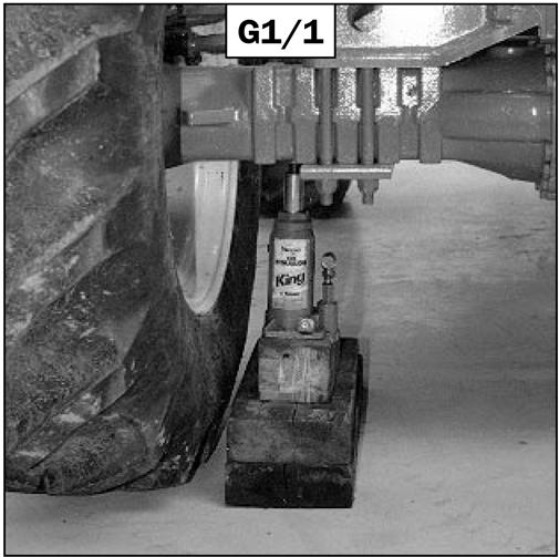
•Place the jack under the flared axle tube, as near as possible to the wheel and adjust the jack (fig. G1/1).
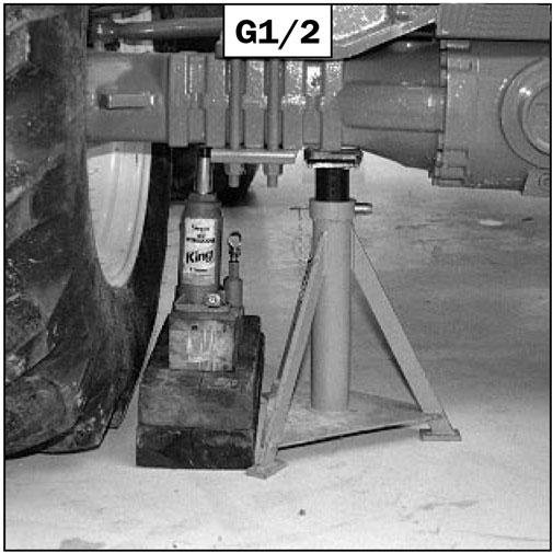
•Lift until the tire comes off the ground, and put the safety support in place under the axle (fig. G1/2).
•Completely loosen and remove the wheel nuts.
•Remove the wheel and roll it to the side.
•Install the new wheel on the wheel hub.
•Replace the nuts by hand. If necessary, grease them.
•Remove the safety support and lower the telescopic handler with the jack.
•Tighten the wheel nuts with a torque wrench (see chapter: 6 - MAINTENANCE: A- DAILYOR EVERY10 HOURS SERVICE for tightening torque).
G1 -WHEELS CHANGE
G -PERIODIC MAINTENANCE WARNING
In the event of a wheel being changed on a public highway, follow this procedure:
For this operation, use a hydraulic jack and a safety support.
•Stop the telescopic handler, if possible on even and hard ground. Apply the parking brake.
•To stop the telescopic handler (see chapter: 4OPERATING AND SAFETYINSTRUCTIONS: G - STOPPING THE TELESCOPIC HANDLER).
•Switch on the hazard warning lights.
•Block the telescopic handler in both directions on the wheel opposite to the wheel to be changed.
•Break loose the nuts of the wheel to be changed.
G2 -ADJUSTING FRONT HEADLAMPS
RECOMMENDED SETTING
Set the dipped beam to -2% in relation to the horizontal line of the headlamp.
ADJUSTING PROCEDURE
-Park the telescopic handler unloaded and in the transport position and facing to a white wall on flat, level ground (fig. G2).
-Check the tire pressures (see chapter: 1 - SPECIFICATIONS: SPECIFICATIONS).
-Place the shift lever in neutral and apply the parking brake.
CALCULATING THE HEIGHTOF THE DIPPED BEAM (H2):
-h1 = Height of the headlamp in relation to the ground
-h2 = Height of the dipped beam
-l = Distance between the headlamp and the wall
-h2 = h1 - (l x 2/100)
G3 -BLEEDING THE FUELSYSTEM
These operations are necessary only in the following cases:
-Acomponent of the fuel system is replaced.
-Adrained fuel tank.
-Running out of fuel.
Ensure that the fuel level in the tank is sufficient and bleed in the following order:
-Open the engine cover.
-Turn on the ignition for three minutes, to give the lift pump time to release air from the filter.
-Switch off the ignition key.
IMPORTANT: Do not engage the starter motor for more than 30 seconds. Let it cool between unsuccessful starting attempts.
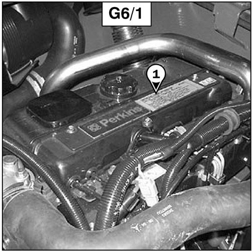
Bleeding The Injectors
-Remove the injectors cover (1) (fig. G3/1).
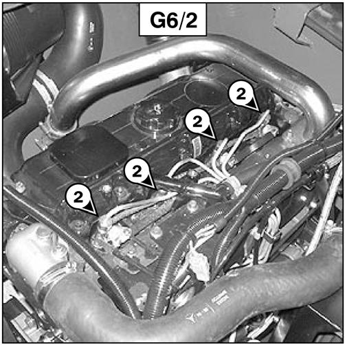
-Loosen the high pressure connectors (2) (fig. G3/2) of all the injectors.
-Tighten the connections while the diesel fuel is flowing out [tightening torque: 22 ft.-lbs. (30 Nm)].
-The engine is then ready to be started.
-Run the engine slowly for five minutes immediately after bleeding the fuel system, to ensure that the injection pump has been bled thoroughly.
NOTE: If the engine runs properly for a short time and then stops or runs irregularly, check for possible leaks in the low pressure circuit. If in doubt, contact your dealer.
-Activate the starter until the diesel fuel flows out free of air at the high pressure connectors (2) (fig. G3/2).