21 minute read
Chapter 5 INSTRUMENTS AND CONTROLS


Description
1 - OPERATOR’S SEAT
2 - SEATBELT
3 - CONTROLAND SIGNALLAMPPANEL
4 - BOOM-MOUNTED WORK LIGHTS (See page 36)
5 - SWITCH PANEL
6 - LIGHTSWITCH, HORN AND TURN INDICATOR SWITCH
7 - IGNITION SWITCH
8 - BRAKE FLUID RESERVOIR AND WINDSHIELD WASHER RESERVOIR ACCESS PANEL
9 - BRAKE FLUID RESERVOIR
10 - WINDSHIELD WASHER RESERVOIR
11 - FUSE AND RELAYS ACCESS PANEL
12 - FUSES AND RELAYS
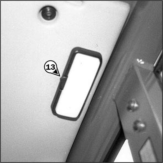
13 - CAB INTERIOR LIGHT
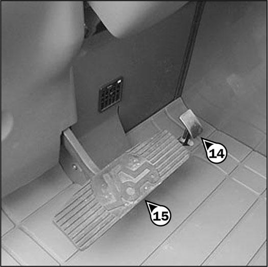
14 - ACCELERATOR PEDAL
15 - SERVICE BRAKE PEDALAND TRANSMISSION CUT-OFF
16 - SHIFTLEVER AND TRANSMISSION CUT-OFF
17 - FORWARD/REVERSE LEVER
18 - PARKING BRAKE LEVER
19 - STEERING SELECTOR LEVER
20 - JOYSTICK CONTROLAND TRANSMISSION CUT-OFF
21 - LOAD CHARTS
22 - AIR CONDITIONING CONTROLS
23 - CAB FILTER VENTILATORS
24 - WINDSHIELD DEFROSTER
25 - HEATING VENTS
26 - DOOR LOCK
27 - LOCK HANDLE FOR UPPER HALF DOOR
28 - RELEASE BUTTON FOR UPPER HALF DOOR
29 - HANDLE FOR REAR WINDOWOPENING
30 - MANUALHOLDER
31 - FRONTLIGHTS (See page 43)
32 - REAR LIGHTS (See page 44)
33 - ENGINE BLOCK HEATER (See page 44)
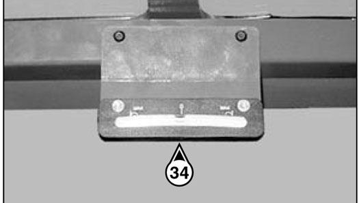
34 - INCLINOMETER
35 - STEERING WHEELPOSITION ADJUSTMENTHANDLE
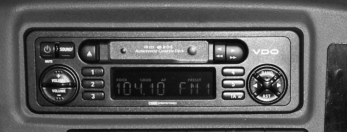
36 - RADIO
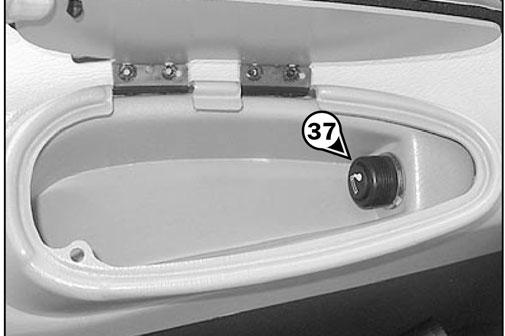
37 - CIGAR LIGHTER AND 12-VDC ACCESSORYOUTLET
38 - ATTACHMENTHYDRAULIC CONTROLFOR CONTINUOS OPERATION AND FLOWCONTROL.
TOWPIN (See page 45)
A- TOWING PIN
B - TRAILER ELECTRIC CONNECTOR
USE OF OPTIONS (See page 46)
1 - Boom Ride Control
2 - Reversible Fan
3 - Second Auxiliary Hydraulic Circuit With Hydraulic Attachment Locking
NOTE: All terms such as: RIGHT, LEFT, FRONT, REAR are meant for an observer seated in the operator’s seat and looking forward.
1 -OPERATOR’S SEAT (standard)
Designed for maximum comfort, this seat can be adjusted as follows:
WEIGHTADJUSTMENT(FIG. A)
It is recommended that the weight be adjusted when the operator is not sitting in the seat.
FORE AND AFTADJUSTMENT(FIG. D)
The depth of the seat may be adjusted to suit the individual.
-Refer to graduation (1) of the seat.
-Turn handle (2) depending on the operator’s weight.
NOTE: It is recommended that the weight should be checked and adjusted before starting the telescopic handler.
HEIGHTADJUSTMENT(FIG. B)
Raise the seat to the desired position, until the ratchet clicks. If the seat is raised above the last notch (stop), the seat drops down to the lowest position.
-Press the right-hand button while moving the seat to find the desired position.
EXTENDING THE HEADREST(FIG. E)
-The height of the headrest can be adjusted by pulling it upwards (the notches will click) up to the stop.
-The headrest can be removed by applying sufficient force to pull it off the stop.
LUMBAR ADJUSTMENT(FIG. F)
SEATCUSHION ANGLE ADJUSTMENT(FIG. C)
The angle of the seat cushion may be adjusted to suit the individual.
-Press the left-hand button while pushing on the seat or relaxing pressure on the seat to find a comfortable position.
This increases the comfort of the seat and the operator’s freedom of movement.
-Turn the handle either left or right to adjust the height or depth of the lumbar support.
ANGLE ADJUSTMENTOF THE BACKREST (FIG. G)
Dirt may adversely affect the correct functioning of the seat. For this reason, make sure the seat is always clean.
-To clean or change the cushions, simply remove them from the seat frame.
Avoid getting the cushion fabric wet when cleaning. Check the color-fastness of the fabric on a small hidden area before using any fabric or vinyl cleaner.
1 -PNEUMATIC OPERATOR’S SEAT (optional)
Designed for maximum comfort, this seat can be adjusted as follows.
WEIGHTAND SEATHEIGHTADJUSTMENT WEIGHTADJUSTMENT(FIG. A)
-Support the backrest, pull the lever and position the back-rest to find the desired position.
Warning
Support the backrest when making adjustments to prevent it from swinging completely forward.
LONGITUDINALADJUSTMENT(FIG. H)
It is advised that you adjust the seat according to your weight when sitting.
-Switch on telescopic handler ignition.
-Push or pull lever (1) until green appears in display (2) indicating correct adjustment according to your weight.
SEATHEIGHTADJUSTMENT(FIG. B)
When weight adjustment has been carried out, you can then modify seat height.
-Adjust the locking lever until you reach the position required. This then locks and the seat will not shift into another position.
MAINTENANCE (FIG. I)
Warning
To avoid causing any damage, do not activate the compressor for more than 1 minute.
-Keep the ignition switched on.
-Push or pull lever (1) until green appears in display (2) and adjust the height of the seat while checking that the green remains visible.
SEATBACKRESTANGLE ADJUSTMENT(FIG. C)
The back-rest angle of the seat may be adjusted to suit the individual.
-The head-rest can be removed by applying sufficient force to pull it off the stop.
LUMBAR ADJUSTMENT(FIG. F)
This increases the comfort of the seat and the operator’s freedom of movement.
Angle Adjustmentof The Backrest
(FIG. G)
-Press the left-hand button while pushing on the seat or relaxing pressure on the seat to find a comfortable position.
FORE AND AFTADJUSTMENT(FIG. D)
The depth of the seat may be adjusted to suit the individual.
-Press the right-hand button while raising or lowering the seat to find the desired position.
EXTENDING THE HEADREST(FIG. E)
-Support the backrest, pull the lever and position the back-rest to find the desired position.
Warning
Support the back-rest when making adjustments to prevent it from swinging completely forward.
HORIZONTALSHOCK ABSORBER (FIG. H)
In certain conditions (e.g., driving with a trailer) it is advised that a horizontal shock absorber be used. The operator’s seat is thus better able to absorb jerks in the direction of travel.
-The height of the head-rest can be adjusted by pulling it upwards (the notches will click) up to the stop.
-Position: 1 Horizontal shock absorber fitted.
-Position: 2 Horizontal shock absorber removed.
LONGITUDINALADJUSTMENT(FIG. I)
-Adjust the seat belt to your body shape, without squeezing your hips and without excess slack.
3 -CONTROLAND SIGNALLAMPPANEL INSTRUMENTS
-Adjust the locking lever until you reach the position required. This then locks and the seat will not shift into another position.
MAINTENANCE (FIG. J)
Dirt may adversely affect the correct functioning of the seat. For this reason, make sure the seat is always clean.
A-HOURMETER AND TACHOMETER
B -ENGINE COOLANTTEMPERATURE
Temperature zones
B1 - Blue zone: 32° - 122°F (0° - 50°C)
B2 - Green zone: 122° - 212°F (50° - 100°C)
B3 - Black/red zone: 212° - 221°F (100° - 105°C)
B4 - Red zone: 221° - 248°F (105° - 120°C)
NOTE: Red indicator lamp “E” comes on between zone B3 and B4.
C -FUELLEVEL
Red zone (C1) indicates that the reserve fuel supply is being used and that engine run time is limited.
SIGNALLAMPS
-To clean or change the cushions, simply remove them from the seat frame. Avoid getting the cushion fabric wet when cleaning. Check the color-fastness of the fabric on a small hidden area before using any fabric or vinyl cleaner.
2 -SEAT BELT
Warning
Do not use the telescopic handler if the seat belt is damaged (not latching, cuts, tears, etc.). Repair or replace the seat belt immediately.
-Sit properly on the seat.
-Check that seat belt is not twisted.
-Place the seat belt at hip level.
-Attach the seat belt and check that it latches.
When activating the electrical system of the telescopic handler, all the red lamps must light and the panel's buzzer must sound to indicate their good working order. If one of the red lamps or the buzzer does not function, carry out the necessary repairs.
D -RED TRANSMISSION OILPRESSURE LAMP
The lamp and the buzzer come on when the pressure in the transmission, when driving forward, is abnormally low. Stop the telescopic handler and look for the cause (insufficient transmission oil level, internal leak in the transmission, etc.).
NOTE: The signal lamp operates in forward travel conditions only. The signal should not be taken into account when the engine is running at idle or is stopped.
E -RED TRANSMISSION OILTEMPERATURE LAMP
The lamp and the buzzer come on when the torque converter oil temperature is abnormally high. Stop the telescopic handler and look for the cause of this overheating.
F -RED BRAKE FLUID LEVELLAMP
If the lamp and the buzzer come on when the telescopic handler is running, stop the engine immediately and check the brake fluid level.
In the event of an abnormal dropping of the fluid level, consult your dealer.
G -RED PARKING BRAKE LAMP
This lamp comes on when the parking brake is applied.
H -RED ALTERNATOR CHARGE LAMP
If the lamps E - F - H - I - J - K and the buzzer come on when the telescopic handler is running, stop the engine immediately and check the electrical circuit and the alternator belt.
I -RED ENGINE OILPRESSURE LAMP
If the lamp and the buzzer come on when the telescopic handler is running, stop the engine immediately and look for the cause (check oil level in engine crankcase).
J -RED ENGINE COOLANTTEMPERATURE LAMP
If the lamp and the buzzer come on when the telescopic handler is running, stop the engine immediately and investigate the cooling system for the cause of the malfunction.
K -RED LAMP- AIR FILTER OR HYDRAULIC RETURN FILTER CLOGGED
The lamp and buzzer come on when the air filter cartridge or the hydraulic return oil filter cartridge is clogged. Stop the telescopic handler and carry out the necessary repairs (see cleaning and replacement requirements in chapter 6 - MAINTENANCE: FILTER CARTRIDGES AND BELTS).
L-GREEN TURN INDICATOR LAMP
M -GREEN SIDELIGHTS LAMP
N -GREEN LOWBEAM LAMP
O -BLUE MAIN BEAM LAMP
4 -BOOM-MOUNTED WORK LIGHTS (OPTION)
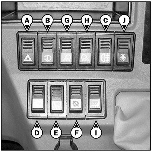
5 -SWITCH PANEL
A-WARNING LIGHTS
This switch enables the left and right turn indicators to be switched on simultaneously, with the ignition off, for use as a hazard indicator. The signal lamp indicates that the switch is being used.
B -BOOM-MOUNTED WORK LIGHTS (OPTION)
This switch lights the work lights mounted at the end of the boom. Pressing the bottom of the switch turns “ON” the boom work lights.
C -REAR FOG LIGHT
This switch lights the fog lights on the rear of the machine. The head lights must be on before this switch can be activated. Pressing the bottom of the switch turns “ON” the rear fog lights.
D -FRONTWINDSHIELD WIPER AND WINDSHIELD WASHER
Pressing the bottom of this switch to the first position operates the windshield wiper. Further pressing and holding the bottom of the switch simultaneously operates the windshield wiper and windshield washer.
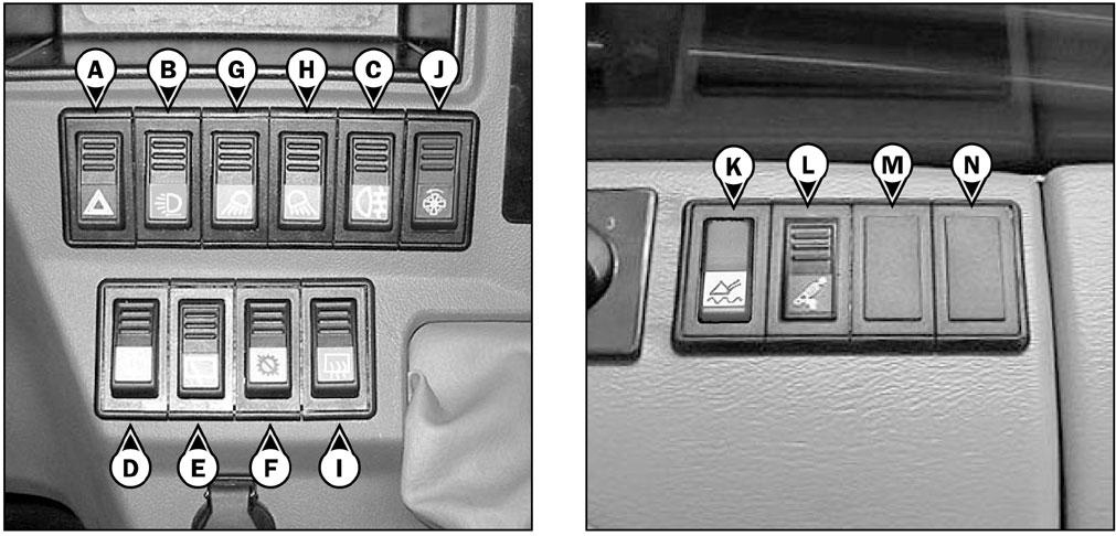
E -REAR WINDOWWIPER AND ROOF WINDOWWIPER
Pressing the top of the switch activates the roof window wiper. Pressing and holding the bottom of the switch activates the rear window wiper.
F -TRANSMISSION CUT-OFF
The switch selects transmission cut-off feature to either the service brake pedal or the joystick control lever.
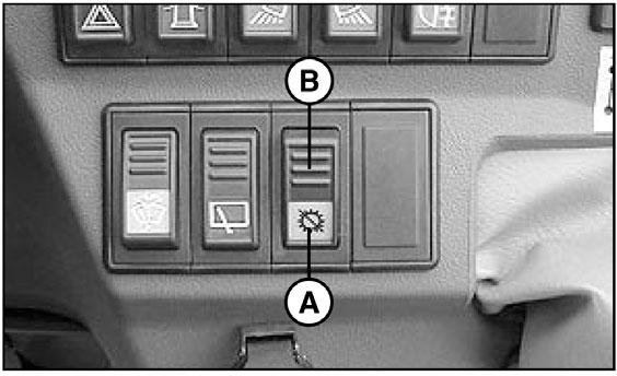
Position: AIndicator lamp on, transmission cut-off to service brake pedal enabled.
Position: B Indicator lamp off, transmission cut-off to joystick control lever enabled.
NOTE: In all cases, transmission cut-off can be effected by using the shift lever.
N -OPTION
6
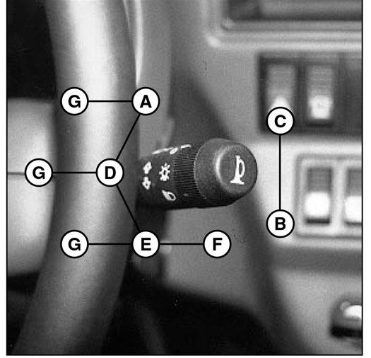
-LIGHT SWITCH, HORN AND INDICATOR SWITCH
The switch controls the visual and audible alarms.
A-All lights are off; the direction indicators do not flash.
B -The right turn indicators flash.
C -The left turn indicators flash.
D -The sidelights and the rear lights are on.
E -The low-beam headlights and the rear lights are on.
F -The high-beam headlights and the rear lights are on.
G -Flashes high-beam headlights when held in this position.
Pressing the end of the switch sounds the horn.
NOTE: The positions D - E - F- G can be used without the ignition being on.
USE OF TRANSMISSION CUT-OFF
Transmission cut-off to brake pedal (position A):
• When loading.
Transmission cut-off to joystick control lever (position
B):
• When driving.
• For inching and continuous stopping and starting (delicate handling). In order to optimize hydraulic movements, cut off transmission to the hydraulic controls lever.
• Starting up on a slope.
G -FRONTWORKING LIGHT
Pressing the bottom of this switch turns “ON” the front work lights located on the top front of the cab.
H -REAR WORKING LIGHT
Pressing the bottom of this switch turns “ON” the rear work light located on the top rear of the cab.
I -OPTION, REAR WINDOWDEFROSTING
J -OPTION, REVERSIBLE FAN
K -OPTION, RIDE CONTROL
L-ATTACHMENTHYDRAULIC LOCKING DEVICE
See chapter: 7 - ATTACHMENTS: INSTALLING ATTACHMENTS.
M -OPTION
7 -IGNITION SWITCH

The key switch has five positions:
P-Ignition off, parking position
O -Ignition switched off and engine stopped
I -Ignition on
II -Pre-heating
III -Start
When the engine starts, return to position I as soon as the key is released.
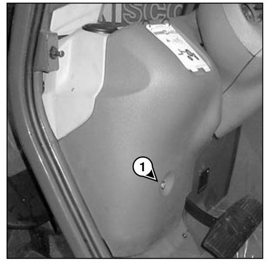
8 -BRAKE FLUID RESERVOIR AND WINDSHIELD WASHER ACCESS PANEL
-Loosen screw (1) and lift up the brake fluid and windshield washer access panel.


K1- Relay transmission cut-off to hydraulic controls
K2- Transmission cut-off relay
K3- Reverse gear relay
K4- Forward gear relay
K5- Buzzer
K6- OPTION
K7- OPTION
K8- Safety system starting switch relay
K9- Flashing unit
K13- Preheating engine relay
K15- Relay cutting power supply to proportional hydraulic controls
9 -BRAKE FLUID RESERVOIR
See chapter: 6 - MAINTENANCE: B - EVERY50 HOURS SERVICE.
10 -WINDSHIELD WASHER RESERVOIR
See chapter: 6 - MAINTENANCE: B - EVERY50 HOURS SERVICE.
11 -FUSE AND RELAYACCESS PANEL
-Lift up the fuse and relay access panel 11.
IMPORTANT: Replace a failed fuse with a new fuse of the same quality and capacity. Never use a repaired fuse.
12 -FUSES AND RELAYS
Asticker on the inside of the access panel gives a clear display of the use of the components described below.
K0- Air conditioning

F1- (10AMAX.) - Attachment hydraulic locking device (7.5A)
- Attachment hydraulic control forced operation (7.5A)
F2- (15AMAX.) - Working rear light (10A)
F3- (10AMAX.) - Rear windshield wiper (7.5A)
- Roof windshield wiper (7.5A)
F4- (10AMAX.) - Engine shut-off solenoid (7.5A)

F5- (10AMAX.) - OPTION (7.5A)
F6- (7.5AMAX.) - Alignment of the wheels (5A)
F7- (15AMAX.) - OPTION
F8- (15AMAX.) - Transmission control (15A)
- Transmission cut-off (15A)
- Reverse lights (15A)
- Backup alarm (15A)
F9- (10AMAX.) - Instrument panel (5A)
F10- (15AMAX.) - Backup alarm (15A)
- Stop switch (15A)
F11- (15AMAX.) - OPTION
F12- (10AMAX.) - Indicator power supply (10A)
F13- (35AMAX.) - Heater (30A)
F14- (25AMAX.) - Cigar lighter (10A)
F15- (25AMAX.) - OPTION
F16- (10AMAX.) - Air conditioner (7.5A)
F17- (15AMAX.) - OPTION
F18- (15AMAX.) - Front working head light (15A)
F19- (15AMAX.) - OPTION
F20- (10AMAX.) - OPTION
F21- (10AMAX.) - Front windshield wiper and windshield washer (10A)
F22- (15AMAX.) - OPTION
F23- (10AMAX.) - Right sidelights (7.5A)
- Sidelight indicator lamp (7.5A)
- Control panel lighting (7.5A)
F24- (10AMAX.) - Left sidelights (7.5A)
F25- (10AMAX.) - Right turn indicators (7.5A)
F26- (10AMAX.) - Left turn indicators (7.5A)
F27- (15AMAX.) - Low beam (15A)
- Low beam indicator lamp (15A)
- Rear fog light (15A)
F28- (15AMAX.) - High beam (15A)
- High beam indicator lamp (15A)
F29- (25AMAX.) - Hazard warning lights power supply (15A)
- Roof light (15A)
F30- (25AMAX.) - Light switch power supply, horn and indicators (25A)
F31- (20AMAX.) - Starter (20A)
F32- (5AMAX.) - Electro-proportional hydraulic control modules (3A)
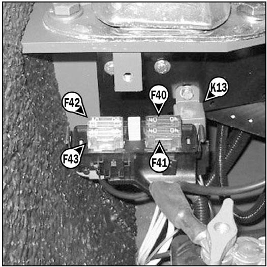
Remove casing 1 and cover 2 for access to fuses F40 to F43 and to relay K13
F40- (40AMAX.) - Telescopic Handler electrical equipment (40A)
F41- (40AMAX.) - Telescopic Handler electrical equipment (40A)
F42- (80AMAX.) - Preheating engine (80A)
F43- (80AMAX.) - Alternator (80A)
Depressing the brake pedal hydraulically activates the internal braking mechanism in the front and rear axles. Depending on the position of the transmission cut-off switch, power to the transmission is cut off. This allows greater engine acceleration and power to the hydraulic system without power to the drive axles while the service brake pedal is depressed. (see: chapter 5 - INSTRUMENTS AND CONTROLS: 5SWITCH PANEL).
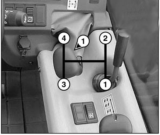
16 -SHIFT LEVER AND TRANSMISSION CUT-OFF
To shift gears, it is necessary to cut off the transmission by pressing the button (1) on the shift lever.

1st gear: To the right, rearward
2nd gear: To the right, forward
3rd gear: To the left, rearward
4th gear: To the left, forward
Shifting The Transmission
Because this telescopic handler has a torque converter, it is not necessary to always start up in 1st gear and progress up through the gears.
IMPORTANT: The choice of transmission gear should be made carefully according to the nature of the work being carried out. Apoor choice may result in an extremely rapid elevation of the transmission oil temperature through excessive slipping of the converter, which could lead to serious damage to the transmission. (It is essential to stop and change the working conditions if the transmission oil temperature indicator light comes on.) This poor choice may also result in a reduction in the telescopic handler's performance in forward speed. When the forward force increases, the forward speed in the chosen gear (for example, 3rd gear) may be lower than the forward speed that could be obtained with a lower gear (in 2nd instead of the 3rd).
In general, use the following gears according to the nature of the work being carried out:
• On the road: Start off in 3rd gear and shift up to 4th if the conditions permit. In hilly areas: Start off in 2nd gear and shift up to 3rd if the conditions permit.
• With a trailer on the road: Start off in 2nd gear and shift up to 3rd if the conditions permit.
• Material handling: Start in 3rd gear, or 2nd gear in restricted spaces.
• Earthmoving: Start in 1st gear.
• Loading (with bucket, manure fork, etc.): Start in 2nd gear.
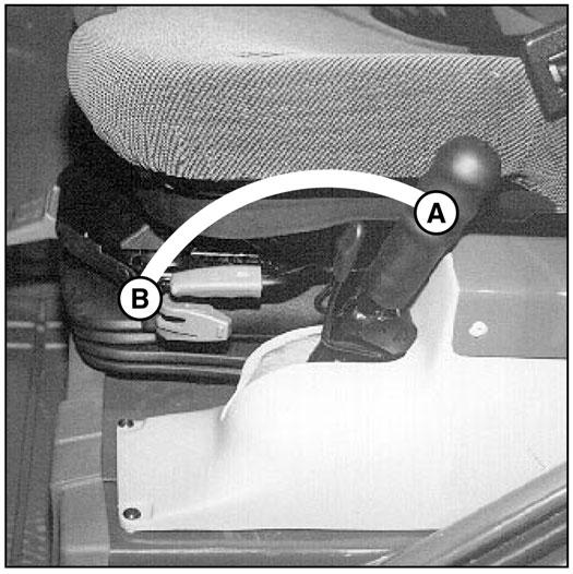
17 -FORWARD/REVERSE LEVER
This lever is used to change the direction of travel (forward or reverse).
NOTE: To prevent damage to the transmission, the telescopic handler should be traveling at a slow speed and not accelerating when changing the direction of travel.
When the forward/reverse lever is in the neutral position, a mechanical lock prevents an inadvertent shifting movement.
FORWARD: Lift slightly and push the lever forward (position A).
REVERSE: Lift slightly and pull the lever rearward (position B).
NEUTRAL: To start the telescopic handler, the lever must be in neutral (position C).
NOTE: The reverse lights and the backup alarm indicate that the telescopic handler is operating in reverse.
Procedure To Move The Telescopic Handler
The telescopic handler is equipped with an electronic unit that prevents the machine from moving unless the operator is seated in the seat.
To move the telescopic handler, the following sequence must be followed:
1 - sit in the operator’s seat, 2 - release the parking brake, and 3 - shift into forward or reverse.
To stop the telescopic handler, the following sequence must be followed:
1 - shift into neutral,
2 - apply the parking brake, and
3 - step out of the telescopic handler.
If this sequence is not followed (for example, leaving the operator’s seat without applying the parking brake), an alarm will sound. The operator must then shift into neutral and follow the sequence.
18 -PARKING BRAKE LEVER
To prevent inadvertent release, the lever is fitted with a safety lock.
-To apply the parking brake, pull the lever rearward (position A).
-To release the parking brake, release the safety lock and push the lever forward (position B).
A-STEERING SELECTOR LEVER
A1 - Front-wheel steer (highway traffic)
A2 - Front and rear wheels steer in opposite directions (4-wheel steer)
A3 - Front and rear wheels steer in the same direction (crab steer)
B -GREEN LAMPS FOR ALIGNMENT OF THE WHEELS
These lamps come on to indicate the alignment of the wheels in relation to the axles of the telescopic handler. The lamp B1 is for the front wheels, and the lamp B2 is for the rear wheels.
C -SWITCH FOR ALIGNMENT OF THE WHEELS
This switch enables alignment of the wheels. The indicator lamp indicates if it is ON.
Wheelalignmentprocedure
-Press the switch (signal lamp ON).
-Shift the hydraulic valve control lever for steering selection Ato position A2 (4-wheel steering).

-Turn the steering wheel and bring the rear wheels into alignment until the lamp B2 is ON.
-Shift the hydraulic valve control lever for steering selection Ato position A1 (highway use).
-Turn the steering wheel and bring the front wheels into alignment until the lamp B1 is ON.
Warning
19 -STEERING MODE SELECTION
Before selecting one of the three steering modes, bring the four wheels into alignment, i.e., in the straightahead position.
Before driving on roads, it is necessary to check the alignment of the rear wheels and to select front-wheel steering mode. The alignment of the rear wheels must be done regularly while driving the telescopic handler, with the help of the green lamps. In case of problems, consult your dealer.
20 -HYDRAULIC CONTROLS AND TRANSMISSION CUT-OFF
IMPORTANT : Do not attempt to alter the hydraulic system pressure by adjusting the pressure regulating valve. In the event of suspected malfunction, contact your dealer. ANYALTERATION MAYVOID THE WARRANTY.
Warning
Use the hydraulic controls carefully without jerking, to avoid accidents caused by sudden movement of the telescopic handler.
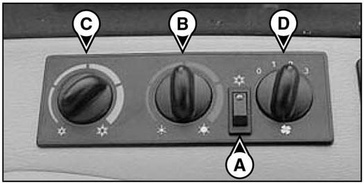
22 -HEATER / AIR CONDITIONER CONTROLS
IMPORTANT: The air conditioner only comes on when the telescopic handler has been started. When using the air conditioning, the doors and windows should be kept closed.
In cold weather: Warm the engine before switching on the compressor, to allow any refrigerant that has collected in the liquid state at the lowest point of the compressor circuit to turn into gas under the effect of the heat given off by the engine, because the compressor is liable to be damaged by liquid refrigerant.
In winter: To ensure proper operation and complete efficiency of the air conditioning unit, switch on the compressor once a week, if only briefly, to lubricate the internal seals.
LIFTING THE LOAD
-Pull the lever Arearward for lifting.
-Push the lever Aforward for lowering.
TILTING THE CARRIAGE
-Move the lever Ato the left for rearward tilt.
-Move the lever Ato the right for forward tilt.
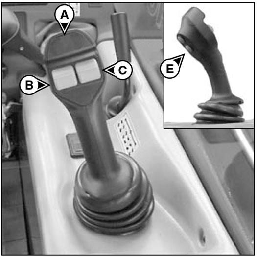
TELESCOPING THE BOOM
-Push the button B up for extension.
-Pull the button B down for retraction.
ATTACHMENT
-Move the button C up or down.
TRANSMISSION CUT-OFF
-Button E (see chapter: 5 - INSTRUMENTS AND CONTROLS: 5 - SWITCH PANEL).

21 -LOAD CHARTS
These charts include the description of the hydraulic controls and the load charts for the attachments used on the telescopic handler.

IMPORTANT: If the air conditioning does not seem to be working properly, have it examined by your dealer (see chapter: 6 - MAINTENANCE: HEVERYTWO YEARS). Never try to repair any problems yourself.
Description Of The Air Conditioning Controls
A-Switch with signal lamp indicating start-up and cut-out of the air conditioning system, if control "D" is in position 1, 2 or 3.
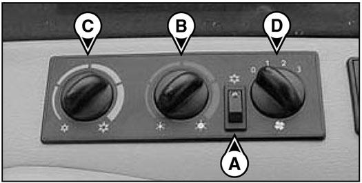
B -Heater air temperature control.
C -Conditioned air temperature control.
D -Air flow setting and fan speed control. In position "0" the air conditioning system no longer functions.
NOTE: Possible losses of water under the telescopic handler are due to condensate discharges caused by the drying effect of the air conditioning, especially with high outside temperatures and high relative humidity.
For the air conditioning to perform properly, the air intakes must not be blocked by frost, snow or leaves.
When the air conditioner is running, at least one of the cab air vents must be open to avoid the risk of freezing the evaporator.
Heating Mode
The controls must be adjusted in the following way:
A-Switch with signal lamp off,
B -At the selected temperature,
C -At the end of travel to the left, and
D -At the selected fan speed 1, 2 or 3.
For optimum effectiveness, close the heater vents.
Air Conditioning Mode
The controls must be adjusted in the following way:
A-Switch with signal lamp on,
B -At the end of travel to the left,
C -At the selected temperature, and
D -At the selected fan speed 1, 2 or 3.
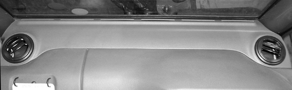
Defrosting Mode
The controls must be adjusted in the following way:


A-Switch with signal lamp on,
B -At the selected temperature,
C -At the selected temperature, and
D -At the selected fan speed 1, 2 or 3.
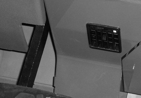
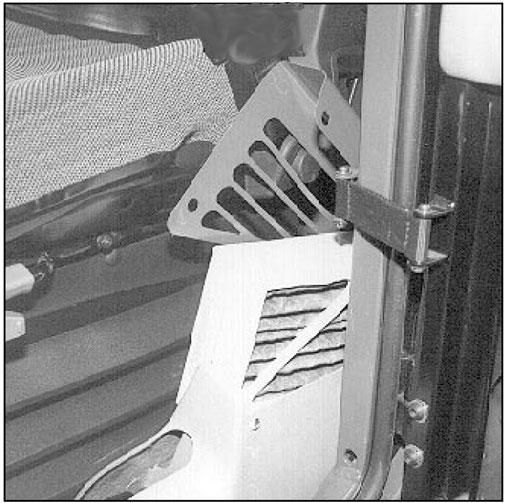
23 -CAB AIR FILTERS
See chapter: 6 - MAINTENANCE: D - EVERY500 HOURS SERVICE.
Vents
These heater vents enable the air to be directed to the interior of the cab and onto the side windows.


Two keys are provided with the telescopic handler to enable the cabin to be locked.

29 -HANDLE FOR REAR WINDOW OPENING
Emergencyexit
Use the rear window as an emergency exit if it is not possible to leave the cab by the door.
30 -MANUALHOLDER
Ensure that the Operator's Manual is in place in the document holder.
31 -FRONT LIGHTS
A- Left front indicator
B - Left front low beam
C - Left front high beam
D - Left front sidelight
E - Right front indicator
F - Right front low beam
G - Right front high beam
H - Right front sidelight

32 -REAR LIGHTS
A- Left rear indicator
B - Left rear stoplight
C - Left tail light
D - Left rear backup light
E - Left rear fog light
F - Right rear fog light
G - Right rear backup light
H - Right tail light
I - Right rear stoplight
J - Right rear indicator
Enables the operator to check that the telescopic handler is in a horizontal position.
35 -STEERING WHEELPOSITIONING HANDLE

This handle enables the angle and height of the steering wheel to be adjusted.
-Turn handle (1) toward Ato loosen and adjust steering wheel.
-Turn handle (1) toward B to lock steering wheel in the position required.


36 -RADIO
To prevent draining the telescopic handlers battery, the radio must be turned off when leaving the machine for extended periods of time. The radio remains on when the ignition key is turned to the off position. Press button 1 on the radio until the display on the radio goes out. Review the radio manual provided with your machine for further radio operation controls.

Continuous Hydraulic Movementof An Attachment
-Make sure the potentiometer (C) is set to 0 %.
-Push rocker switch (A) up or down (depending on the type of attachment), press button (B) and release switch (A). The red indicator lamp (1), flashes to indicate that it is in operation.

-Set the required flow rate using potentiometer (C).
-To stop continuous hydraulic movement of the attachment, push rocker switch (A) up or down, or press button (B). Indicator lamp (1) goes out.

-Set potentiometer (C) back to 0 %.
Warning
Never leave the cab without resetting the potentiometer (C) to 0 %. Before starting the telescopic handler, make sure the potentiometer is set to 0 %.
Warning
This device must only be used with attachments that require continuous hydraulic flow, such as a rotary broom or cement mixer. It is strictly forbidden to use it in material handling operations and other applications, such as with a winch.
Enables the attachment to be hydraulically locked to the carrier using the auxiliary hydraulic circuit. See chapter: 7 - INSTALLING ATTACHMENTS.
Tow Pin
Located at the rear of the telescopic handler, this device is used to attach a trailer. Its capacity is limited for each telescopic handler by the authorized gross vehicle weight, tractive effort and maximum vertical force on the coupling point. This information is given on the manufacturer's plate fixed to each telescopic handler (see chapter: 1 - SPECIFICATIONS AND CONTROLS: IDENTIFICATION OF THE TELESCOPIC HANDLER).
-To use a trailer, see current regulations in your state/province (maximum running speed, braking, maximum weight of trailer, etc.).
-Verify the trailer's condition before using it (tire condition and pressures, electrical connection, hydraulic hose, braking system).
Warning
Do not tow a trailer that is not in good working condition. Using a trailer in poor condition may affect the telescopic handler's steering and braking, and cause an accident.
Warning
If an assistant helps in connecting or disconnecting the trailer, this person must always be visible to the operator and wait until the telescopic handler has stopped, the parking brake is on and the engine is stopped before performing the operation.
A-TOW PIN
CONNECTING AND DISCONNECTING ATRAILER
Warning
Be careful not to get your fingers caught or crushed during this operation.
Do not forget to put clip (1) back in place. When disconnecting, make sure that the trailer is supported independently.
-To connect a trailer, position the telescopic handler as close as possible to the trailer hitch ring.
-Apply the parking brake and turn off the engine.

-Remove the clip (1), lift the trailer pin (2) and insert (or remove) the trailer hitch ring.

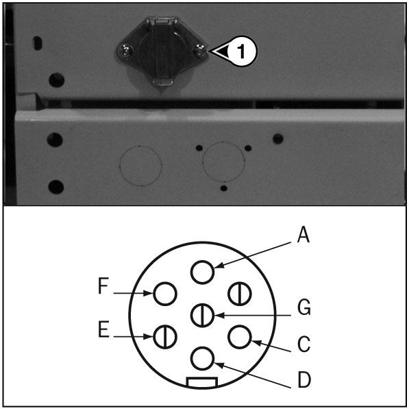
B -TRAILER ELECTRIC CONNECTOR
This 7-pin connector enables electrical power supply connection for a trailer or signal bar.
A- Left turn indicator
C - Ground
D - Right turn indicator
E - Right tail light
F - Rear stoplight
G - Left tail light
Use Of Options
1 -BOOM RIDE CONTROL
The boom is suspended to reduce shaking of the telescopic handler on rough ground (e.g. moving straw in a field).
Operation
-Set the forks or attachment on the ground and raise the front wheels a few inches only.
-Press switch Ato the A1 position, the visual indicator comes on indicating that boom ride control is activated.
-Press switch Ato the A2 position, the visual indicator goes out indicating that boom ride control is deactivated.
-When the engine is turned off, boom ride control is automatically deactivated.
Warning
Boom ride control is active to a lifting height of 9.75 feet (3 m) from the axis of articulation of the carriage with respect to the ground with the boom retracted. When you move beyond this height or make another hydraulic movement (tilting, telescoping, attachment), boom ride control is momentarily deactivated and the visual indicator of switch Agoes out.
2 -REVERSIBLE FAN
The fan blades are rotated to direct the air flow in the opposite direction through the radiator to clean chaff form the radiator.
Operation
-Start the engine.
-Press bottom of switch J. Green LED should come on.
-Timer is set to rotate the fan blades approximately every 3 minutes. Check by placing a piece of paper on radiator. During normal operation it draws air in and during cleaning it blows air out.
-To switch off, press top of switch J. Green LED should go out.
3 -SECOND AUXILIARYHYDRAULIC CIRCUIT WITH HYDRAULIC ATTACHMENT LOCKING
Enables the use of two hydraulic functions on the attachment circuit.
Operation
-Button one not pressed, button two controls the first auxiliary hydraulic function.

-Press button one, button two then controls the second auxiliary hydraulic function.
-Press switch three to lock the hydraulic function of button one. The lamp four lights to indicate this function is activated.