3 minute read
Chapter 7 DECALS


Generalinformation
Caution
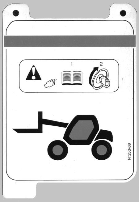
ALWAYS read and follow the safety precautions and information shown on decals. If any decals are damaged or unreadable, or if the unit is repainted, the decals must be replaced. If repainting, BE SURE that all decals that apply to your machine are affixed in their proper locations
When a decal is applied on a part that is to be replaced, make sure that the replacement part has the decal applied or apply a new decal.
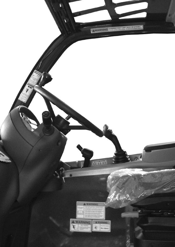
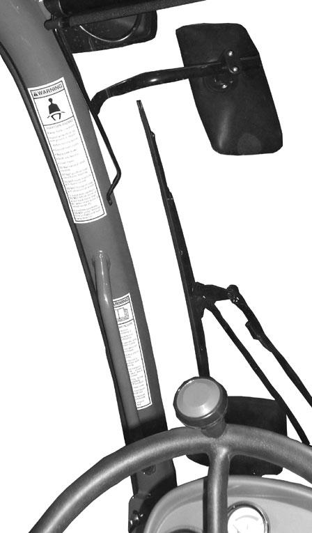
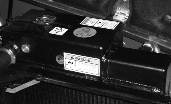
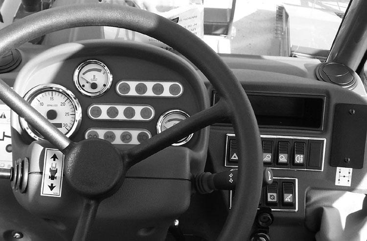
Decal location information is provided to assist in the proper selection and application of new decals, in the event the original decals become damaged or the machine is repainted.
For correct replacement of decals, compare the location photographs to the machine before starting to refinish the unit. Check off each required decal using the illustration reference number to find the part number, description and quantity in the list. Refer to the appropriate illustration for replacement locations.
NOTE: Refer to the Safety chapter of this manual for the specific information provided on the various safety decals.
New Decalapplication
Before applying new decals, surfaces must be free from dirt, dust, grease and other foreign material. To apply a solid-formed decal, remove the smaller portion of the decal backing paper and apply this part of the exposed adhesive backing to the clean surface while maintaining proper position and alignment. Slowly peel off the other portion of the backing paper while applying hand pressure to smooth out decal surface. To apply a die-cut decal, first remove the backing paper. Then, properly position the decal onto the clean mounting surface. After the decal is firmly applied and smoothly pressed down, remove the front covering paper.
Decal Kits
105160CT7-23 Turbo Telescopic Handler
NOTE: Decals may be purchased in kits or individually.

Introduction
Chapter 8
Attachments
-The telescopic handler can be used with interchangeable equipment, called attachments.
-Awide range of attachments, specially designed and suitable for the telescopic handler is available and approved by GEHL.
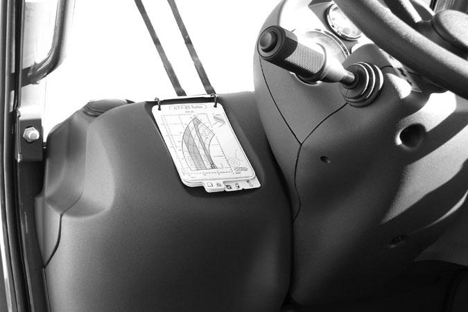
-Attachments are delivered with a load chart applicable to the telescopic handler. The operator's manual and the load chart should be kept in the place provided in the telescopic handler. For standard attachments, their use is covered by the instructions contained in this manual.
-Some particular uses require an adaptation of the attachment, which is not provided in the listed options. Consult your dealer.
Warning
Only attachments approved by the manufacturer are to be used on GEHLtelescopic handlers (see chapter: 7 - ATTACHMENTS: TECHNICALSPECIFICATIONS OF ATTACHMENTS). The manufacturer's liability will be denied in case of modification or adaptation without the manufacturer’s approval.
IMPORTANT: Certain attachments may, when the boom is lowered and retracted, come into contact with the front tires and cause damage to them, if the attachment is tilted forward. TO AVOID THIS RISK, EXTEND THE BOOM SO THAT SUCH CONTACT IS NOT POSSIBLE.
Warning
Maximum loads are defined by the capacity of the telescopic handler, based on the attachment’s mass and center-of-gravity. If an attachment has less capacity than the telescopic handler, never exceed the attachment’s limit.
Installing Attachments Warning
A-ATTACHMENT WITHOUT HYDRAULICS AND WITH HYDRAULIC LOCKING DEVICE
Installing An Attachment
-Ensure that the attachment is in a position for locking it to the carriage. If it is not correctly oriented, take the necessary precautions to safely position it.
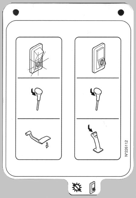
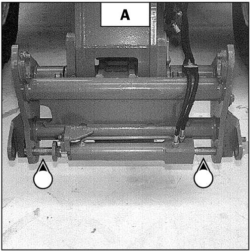
-Check that the pins on the locking cylinder are retracted (fig. A).
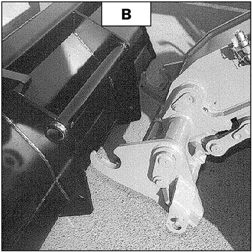
-Park the telescopic handler with the boom lowered in front of and in line with the attachment. Tilt the carriage forward (fig. B).
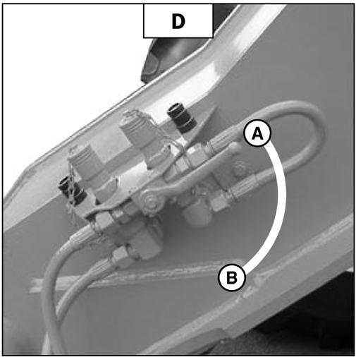
Always close the valve to position B (fig. D) after locking on the attachment, to avoid accidental unlocking, and to use the attachment safely.
Hydrauliclyreleasing
-Place the valve in position A(fig. D), with the hydraulic circuit for attachment locking “open.”
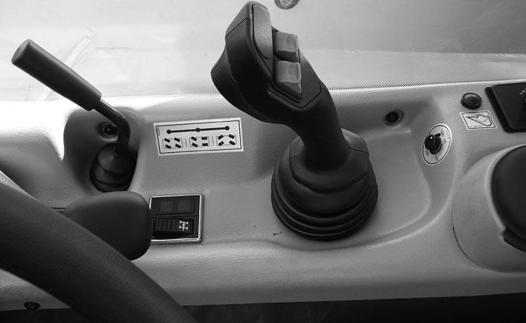
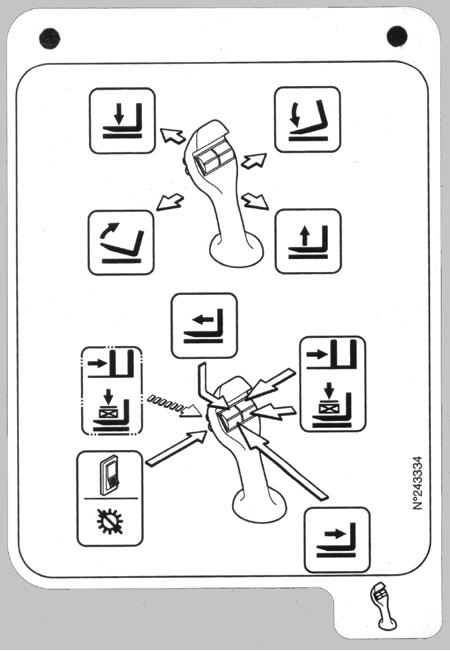
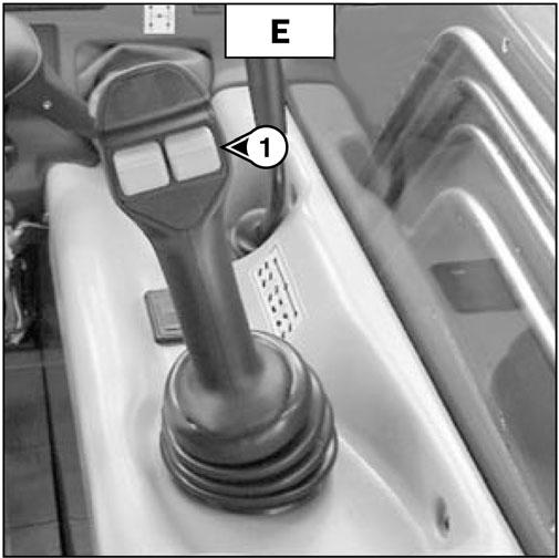
-Switch button (1) (fig. E) of the hydraulic control valve joystick down to completely release the attachment.
Removing An Attachment
-Proceed in the reverse order of paragraph INSTALLING AN ATTACHMENT
-Be sure to place the attachment flat on the ground and in a closed position.
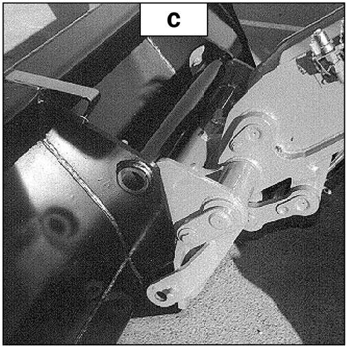
-Bring the carriage under the locking tube of the attachment, slightly lift the boom, and tilt the carriage rearward to position the attachment (fig. C).
-Lift the attachment off the ground to ease locking.
HYDRAULICLYLOCKING
-Place the selector valve in position A(fig. D), with the hydraulic circuit for attachment locking “open.”
-Switch button (1) (fig. E) of the hydraulic control valve joystick up to lock the attachment on the carriage.
-Close the valve to position B (fig. D), with the hydraulic circuit for attachment locking “closed.”
Deactivating The Hydraulic Release Control
Operators can change an attachment without leaving the operator’s station, by cutting the electrical power to the hydraulic control.
-Leave the valve in position A(fig. D).
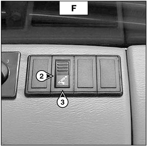
-Use switch (2) (fig. F) to cut the electrical power to the hydraulic control. The circuit is inactive when indicator (3) (fig. F) is “on.”
Warning
Always switch off the electrical power to the circuit using switch (2) (fig. F) after each change of attachment to avoid accidental release, and to use the attachment safely.


