
4 minute read
Operation


Lowering
Lower the loader unit as follows:
☞ Make sure no one is near the machine.
☞ Push and hold control lever 10 forward C
➥ Until the loader unit is completely lowered.
☞ Return control lever 10 to neutral.
IMPORTANT!
The hydraulic system of the machine is still pressurized even when the engine is not running. The hydraulic quick c ouplers can be released, but they cannot be re-attached because the hydraulic lines are pressurized. Therefore:
☞ Depressurize the sections of the system and hydraulic lines that you want to open before starting setup or repair work (e.g., fitting/removing an attachment).
Depressurize as follows:
☞ Apply the parking brake –see Parking brake [13] on page55.
☞ Turn off the engine.
➥ Do not turn off the ignition.
☞ Press and hold tip switches 77 and 78 on the control lever for about 5 – 8 seconds.
➥ Hydraulic lines are depressurized.
☞ Turn off the ignition and remove the ignition key.
Re-installing attachments
Fitting attachments onto the quickhitch facility
Re-installing attachments is described below for the standard bucket. If you are fitting or removing attachments with their own hydraulic functions, you must follow the information provided in the Operator’s Manual of the attachment.
WARNING!
The attachment must always be locked onto the quickhitch facility –Accident risk.
☞ Before working, be sure that the attachment is locked onto the quickhitch by using the lock cylinder. Be sure that you can see the lock pins on both sides of the mounting holes on the attachment.

Re-install as follows:
☞ Drive the machine up to the attachment.
☞ Lower loader unit E by pressing control lever 10 forward C
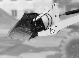
☞ Tilt the quickhitch facility forward by pushing control lever 10 to the right B
☞ Adjust the height of pin shanks G of the quickhitch facility so that they are under catch hooks F of the attachment.
☞ Drive the machine forward until pin shanks G of the quickhitch facility are directly beneath the catch hooks of attachment F
☞ Raise loader unit E until pin shanks G engage in pin shanks F of the attachment. To do this: Pull control lever 10 rearward D.
☞ Fully tilt in the quickhitch facility. To do this: Push control lever 10 to the left A .

Locking: attachments without hydraulic function
Secure the attachment with lock pins H of the quickhitch facility. To do this:
☞ Press tip switch 78 on the control lever.
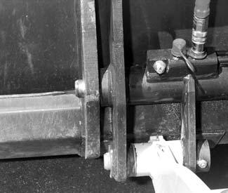
➥ Lock pin H engages in the mounting holes of the attachment.
➥ Make sure that the attachment is safely locked with lock pins H
☞ Lock the 3rd control circuit by using rocker switch 56:
➥ –see Locking 3rd control circuit on page82.
WARNING!
You must be able to see lock pins H on the left and right of the mounting holes on the attachment. The attachment is not safely locked unless you can see the lock pins.
Locking: attachments with hydraulic function
☞ Turn off the engine.
➥ Do not turn off the ignition.
☞ Apply the parking brake.
☞ Unlock the 3rd control circuit with the rocker switch 56 –see Locking 3rd control circuit on page82.
☞ Depressurize the 3rd control circuit
➥ –see Depressurizing the quick couplers on the loader unit on page83.
☞ Attach the hydraulic and electrical connections (if used) for the attachment by following its Operator’s Manual.
Connection of electrically operated attachments (option)
The machine can be fitted with a 4-pole front and/or rear socket. Rocker switch 53 turns the electric power supply on or off for electrically operated attachments (such as a spray water pump for a rotary broom).
Power supply for front attachments (option) ON ☞ Press rocker switch 53 down to position B.
➥ Power supply at the front socket is turned on.
➥ Indicator in switch comes on. OFF ☞ Press rocker switch 53 down to position A.
➥ Power supply is interrupted.
➥ Indicator turns off.
Removinganattachmentfromthe quickhitchfacility
WARNING!
The attachment must be placed on the ground so that it will not fall over when removed –
Risk of personal injury.
☞ Position the attachment so that after unlocking it will stand safely and not tip over.
Take the attachment off the quickhitch facility as follows:
☞ Be sure that the attachment is empty and up.
☞ Tilt in the quickhitch facility by pushing control lever 10 to the left A
☞ Lower the loader unit until the attachment is about 2–4“ (5–10cm) above the ground by pushing control lever 10 forward C
☞ Unlock the 3rd control circuit by using rocker switch 56: –see Locking 3rd control circuit on page82.
For attachments with hydraulic function
☞ Turn off the engine.
➥ Do not turn off the ignition.
☞ Apply the parking brake.
☞ Unlock the 3rd control circuit by using rocker switch 56:
–see Locking 3rd control circuit on page82.
☞ Depressurize the quick couplers:
–see Depressurizing the quick couplers on the loader unit on page83.
☞ Change over the quick couplers on the lock cylinder:
• Connect flexible line A onto the right plug D of the quickhitch facility.

• Connect flexible line B onto the left plug C of the quickhitch facility.
• Remove electrical connections (if necessary).
☞ Start the engine.
☞ Open the lock on the quickhitch facility. To do this:
➥ Press tip switch 77 on control lever 10
☞ Slightly tilt the quickhitch facility forward. To do this: Push control lever 10 to the right B
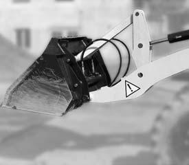
☞ Lower the loader unit. To do this:
➥ Push control lever 10 forward C
As soon as the pin shanks of quickhitch facility F are beneath the catch hooks of attachment E:
☞ Release the parking brake.
☞ Reverse the machine away from the attachment.
