6 minute read
Assembly


Check All Parts On Packing List
For Export Shipment assembly procedure, follow steps 1 through10.
For Domestic Shipment assembly procedure, follow steps 3 through 10.
Note: Use of the parts diagrams and parts listings in the Repair Parts catalog (# 5RPMAN294P) may facilitate assembly of the disk harrow.
STEP 1. ASSEMBLING GANGS
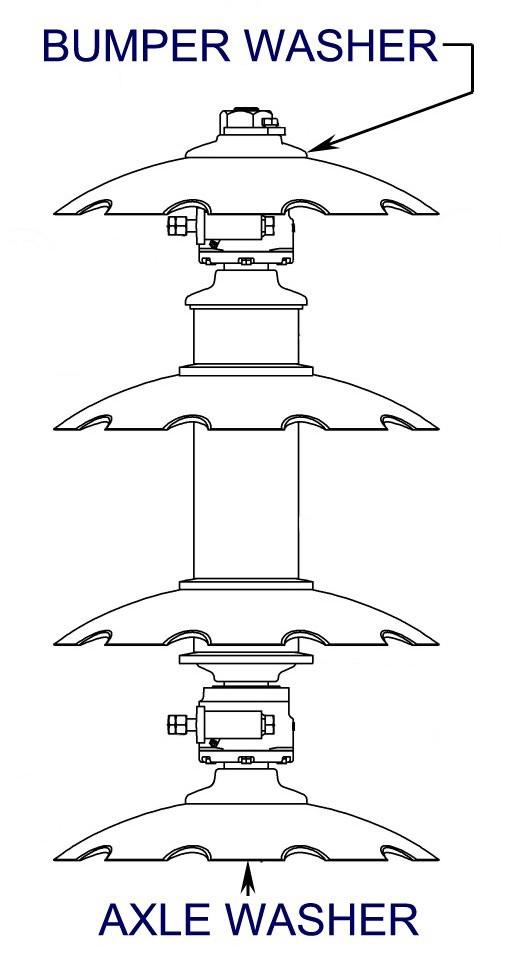
For shipping purposes, the bearings, spacers, axle washer, bumper washer, axle nuts and axle nut locks are shipped bundled together.
To assemble the gangs, these following steps should be observed.
Mount disk blades on each axle assembly as shown. The number of disks and spacers will vary for each size gang.
A. Remove the axle nut on the bumper washe r end of the shipping assembly. The bumper washer is the one that fits the convex surface of the disk blade.
B. Remove all bearings and spacers on the axle. This leaves only the bumper washer, an axle nut lock and one axle nut on the axle.
C. Important: Care should be taken to prevent damage to the axle threads as parts are slid off and on the axle.
D. Slide one disk blade down the axle until it contacts the axle washer. Note: The axle washer fits the concave side of the disk blade. Bearings and spacers have concave and convex ends. Curvatures must mate with disks or the gangs will not stay tight and damage will result. Now, slide a bearing onto the axle.
Assembly
STEP 1. ASSEMBLING GANGS - cont.
E. Raise the axle into a vertical position. Axle, blade and bearing will now stand in an upright position without being held. If the axle washer is not snug against concave side of the disk blade, it will be necessary to tilt axle and disk blade and slide a short 1" x 4" block of wood underneath the disk. Be sure to position it between the nut and the floor or ground. This assures that the threaded end of the axle will be visible when the gang is completely stacked. Note: If this procedure is not followed, the shaft will be too short and the nut cannot be installed.
CAUTION: G ang components are heavy. Two-person gang assembly is recommended. Follow Safety Guidelines.
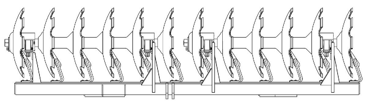
F. Refer to the Illustration and continue to slide the disks, spacers, and bearings down the axle exactly in the order shown. Important: Make sure that concave and convex faces on the washers, bearing assemblies, and disk spacers coincide with the faces of the disks. Note: Concave and convex flanges on the bearing assemblies are factory mounted to correspond to the front and rear gangs in order to have the grease fittings always facing to the rear. This makes it easier to grease the bearings.
G. After the last disk blade is in place, place the bumper washer onto the axle. Replace axle nut after applying lubricant to threads. Tighten nut to remove all slack. Final tightening will be done when the gang is in the horizontal position.
H. Use an overhead crane or hoist to lower disk gang to horizontal position on floor. Use chock blocks to prevent the gang assembly from rolling. Using the axle nut wrenches, tighten both axle nuts as tight as possible.
For best results and added leverage, place a four or five foot length of 2-inch pipe on each axle nut wrench to serve as handle extensions. It may be necessary to hit the pipe extension with a hammer to meet recommended lbs/ft of torque as set forth in the AXLE NUT TORQUES chart found in the MAINTENANCE section - TIGHTEN GANG
AXLE NUTS. Mount axle nut locks to axle and bumper washers and secure with hex bolts and lock washers.
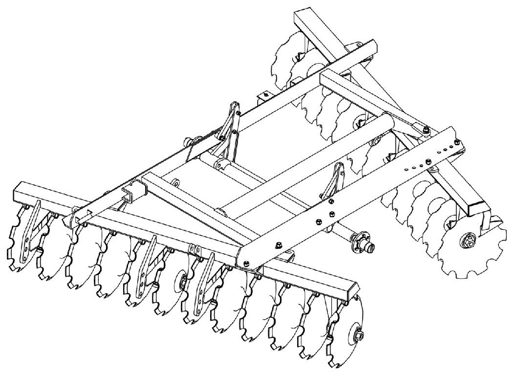
STEP 2. INSTALLING GANGS ON GANG CARRIERS
Where lifting facilities are available:
A. Position front gang assembly with concave side of disks to right, as viewed from the rear.
B. Position rear gang assembly with concave side of disks to left, as viewed from the rear.
C. Place gang carriers on corresponding gang assemblies and attach to bearing standards with the bearing hex bolts, hex jam nuts, hex nuts and bearing wear plates. Where lifting facilities are limited:
A. Position gang carriers upside down. Place gang assemblies on gang carriers and attach to bearing standards with the bearing hex bolts, hex jam nuts, hex nuts and bearing wear plates.
B. Turn completed assemblies of gangs and gang carriers right side up.
C. Install disk scrapers.
STEP 3. INSTALLING GANG C ARRIERS TO FRAME
Place the gang carriers in approximately the correct position on a flat surface and securely block them in an upright position. Place the frame on top of the gang carriers and bolt in place with hex bolts, lock washers, flat washers and hex nuts provided. Note: Place flat washers against all slotted holes. Inserting the pivot bolts first facilitates easy assembly. Gangs may then be pivoted to the desired angle beneath the frame and bolted in place with appropriate hardware.
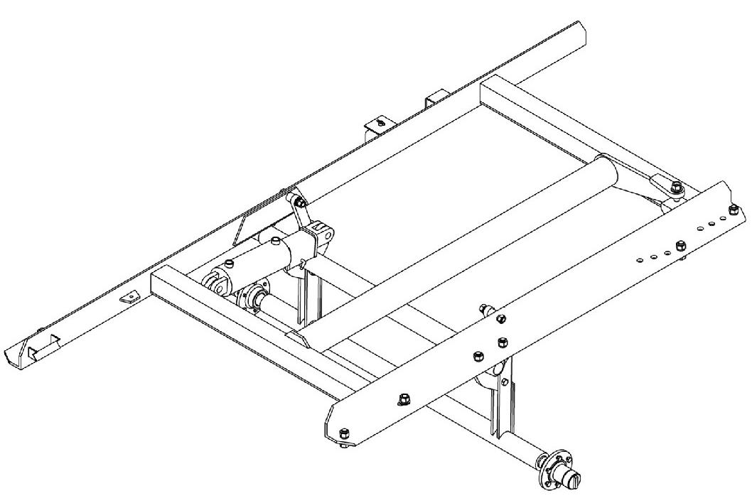
STEP 4. INSTALLING TRANSPORT ASSEMBLY
The transport assembly, with hubs in place, should be attached to the bell crank and guide link which are already in place on the frame. There are bearing studs and bushings provided with the transport assembly for attaching. Note: The transport assembly for Frontier Models DH4411 are included as part of the 5RPAW1400I Frame and Transport Assembly. Model DH4414 uses the 5RPAW4140A Frame Assembly and separate Transport Assembly 5RP3046787.
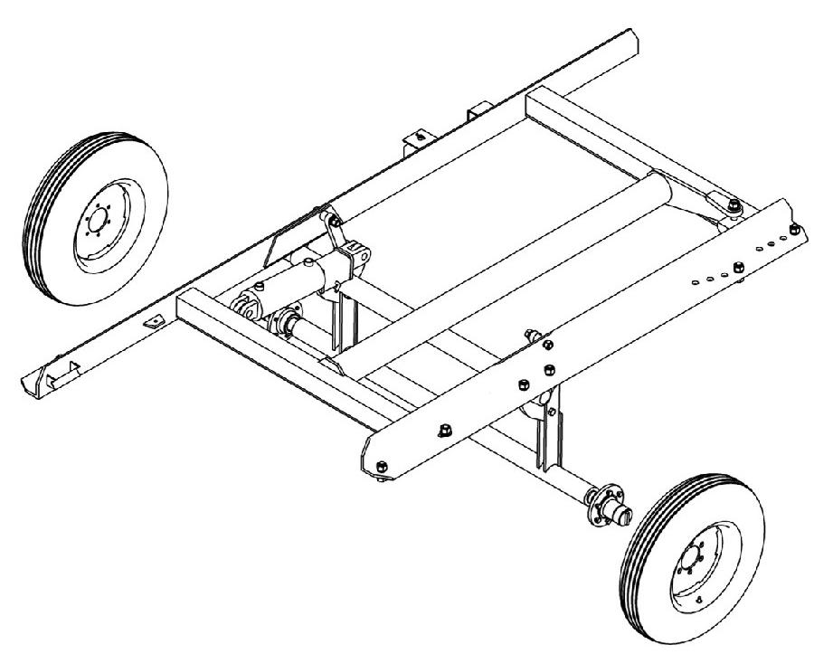
STEP 5. INSTALLING WHEEL ASSEMBLIES
The wheel and tire assemblies should be attached to the hubs with studs and lug nuts (8 or 10 per hub) provided on hub assemblies. Wheel bearings have been properly adjusted and lubricated at the factory. When you mount wheel assembly ont o hubs, make sure the valve stem is to the outside (lug bolt side). Inflate tires to recommended tire pressure for best flotation as stated in the MAINTENANCE section - TIRE PRESSURE CHART :
Note: Torque lugs on the 8-bolt hubs to 80-100 lb/ft. Torque lugs on the 10-bolt hubs to 250 lb/ft.
STEP 6. INSTALLING OFFSET BAR AND LEVELING SPRING ROD
A. Bolt the offset bar to the hitch plates on the front gang carrier with the bolts and bushings provided. Hitch plates are furnished with (3) three adjustment holes. For normal operation, set the offset bar so that it will be as close to level in the plowing position as possible when attached to the tractor drawbar.
B. The leveling spring rod assembly should be attached between the spring rod brackets located on the front gang carrier and those on the offset bar and secured with the hex bolts, lock washers and hex nuts. On model OD1314 the leveling spring attaches to a leveling bracket that is attached to the rod brackets located on the front gang carrie r. The other end is attached to the brackets on the offset bar.
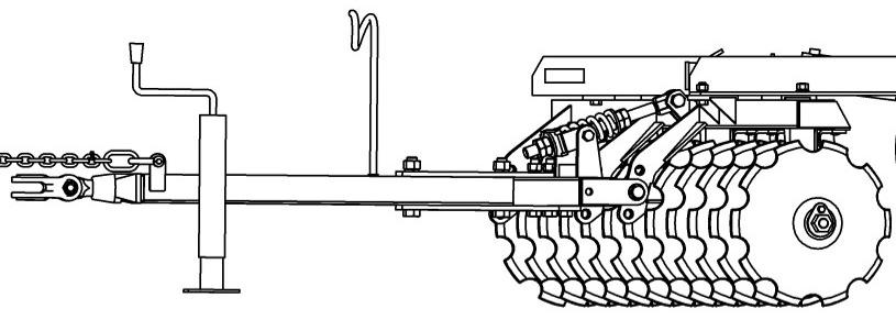
STEP 7. INSTALLING DRAWBAR
The drawbar is attached to the offset bar with bolts that go through the bottom drawbar plate first and then thru the top drawbar plate. Secure hex bolts with lock washers and hex nuts provided. Note: The drawbar plates should be placed so that the drawbar pull point is to the left of the center and approximately in line with the left frame rail (standing behind the disk and looking toward tractor). The final adjustment should be made, if needed, after the harrow has been put into operation.
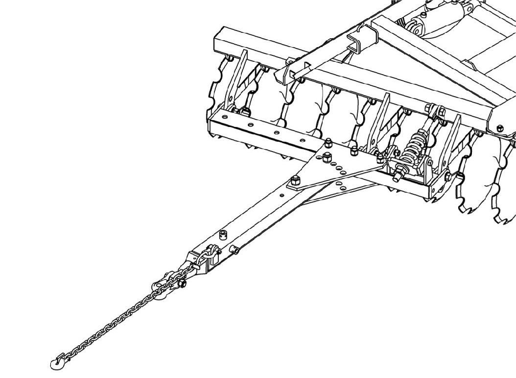
STEP 8. ATTACH JACK ASSEMBLY
Pin the jack stand to the hitch point located on the left hand side of the drawbar assembly. Whenever transporting or plowing, unpin jack and place in the convenient storage position located on top of the drawbar.
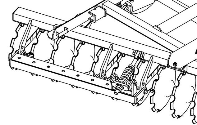
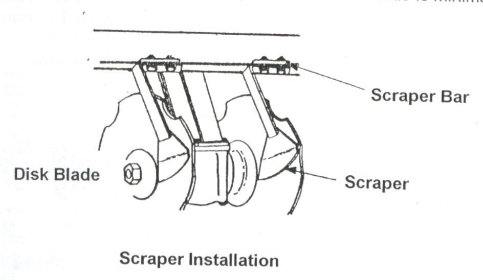
STEP 9. ADJUSTING THE SCRAPERS
Adjust the scrapers as shown in the Illustration. On domestic shipments, scrapers come from the factory mounted to the rear of the gang carriers and should be adjusted so that they do not come in contact with the disk blade as it turns. They should be slightly closer at the scraper point so that the trash build-up between the disk blades and the scrapers is minimal. The heel of the scraper needs to be approximately 1/4" from the disk blade.
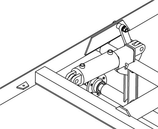
STEP 10. INSTALLING HYDRAULIC CONTROL GROUPS
A. The hydraulic cylinder should be attached to the harrow cylinder brackets with the pins provided. The base end of the cylinder connects to the front of the frame assembly and the rod end goes to the bell crank on the transport assembly.
B. Attach the hydraulic hose holder to the drawbar by inserting it through the hole located just in front of the top drawbar plate and secure with lock washer and hex nut.
C. After connecting the two hydraulic hoses and the right angle fittings to the cylinder ports, feed hoses through the hose holder and install quick couplers on the hose ends.