2 minute read
Assembly ATTACHMENT ASSEMBLY

from Frontier Hinge Wheel Off Set Disk Harrow DH4317 DH4320 Assembly & Operating Instruction Manual(5RPMA

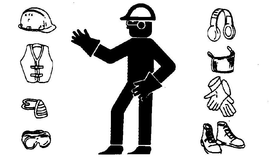
CAUTION: Wear protective clothing and safety equipment appropriate to the job. Work safely to avoid injury and observe all safety messages.
Read all assembly instructions and carefully observe illustrations.
Install Safety Chain
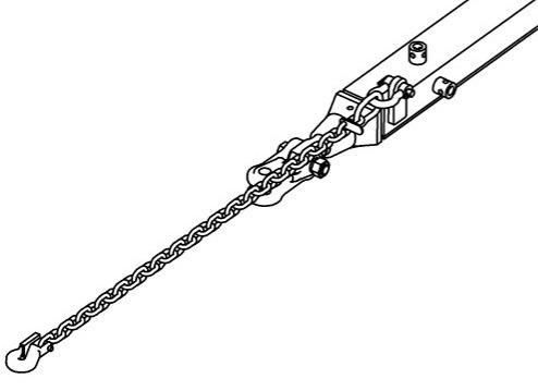
Attach safety chain by pinning shackle through hole in bracket on left front side of drawbar assembly. Secure with the shackle pin and cotter pin.
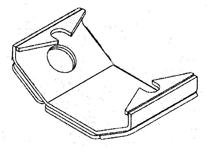
Bearing Wear Plate S
The heavy duty bearing wear plates come from the factory already installed on the bearing assemblies. If it becomes necessary to replace a wear plate, follow these instructions: Remove the mounting bolts from the bearing assembly, and place the bolt heads into the slots of the wear plate. Now, I nsert the mounting bolts through the bearings and secure to gang carrier bearing standards with the hex jam nuts and hex nuts provided.
Assembly
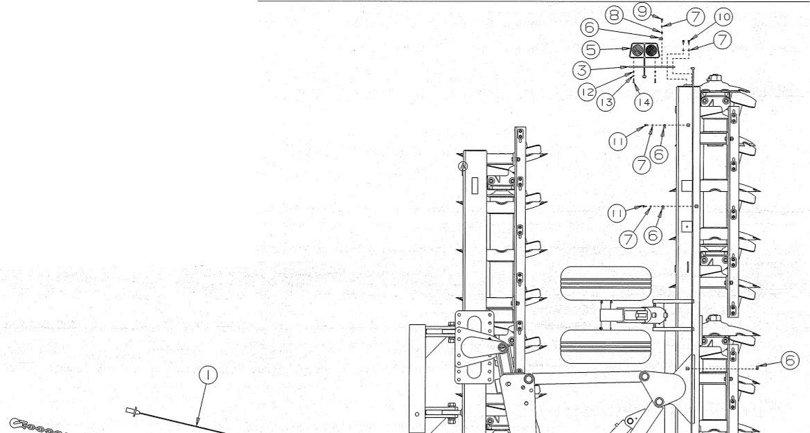
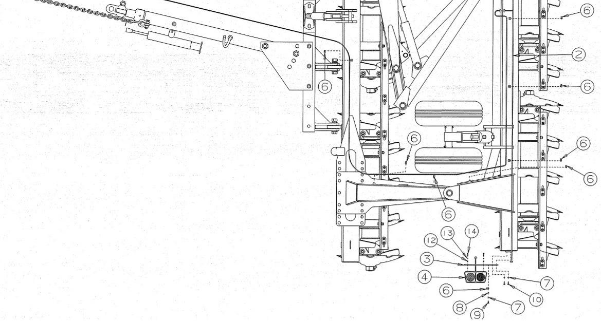
Install Warning Ligh Ts
Refer to Light Group Assembly shown in Repair Parts List Manual (Part # 5RPMAN296P) for specific parts details.
1. Attach light brackets to the ends of the rear gang carrier.
2. Attach the lights to the brackets so that the red lens faces rearward with the amber to the top, visible from both front and rear.
3. Connect the wishbone harness marked left and right to each of the lights.
4. Route the wishbone harness around the frame. The wire clamps will share the bolt used on the hydraulic hose clamps in some places. When installed make sure to tighten all hose clamps. Important: Insure that appropriate hoses are left slack as outlined in STEP E and STEP F of the INSTALL HYDRAULIC CONTROL GROUP assembly instructions.
5. Secure the wishbone harness with the clamps provided in the light group assembly.
6. Attach the straight harness to the wishbone harness.
7. Secure the straight harness to the drawbar with a clamp. Store the excess length and the plug in the hose mast.
Note : Refer to the illustration on the following pages.
Specifications
Specifications
SUGGESTED REPAIR PARTS (DH4317 & DH4320)
MANUALS (OPERATOR’S & PARTS)
If additional manuals are needed for the Frontier DH4317 and DH4320 Offse t Disk Harrows, they can be ordered from your Frontier dealer.
Specifications
SPECIFICATIONS - HEAVY DUTY OFFSET DISK MODELS
DH4317 & DH4320
FEATURES:
Patented hinge-wheel offset harrow line…built rugged and designed to meet today’s tough plowing needs.
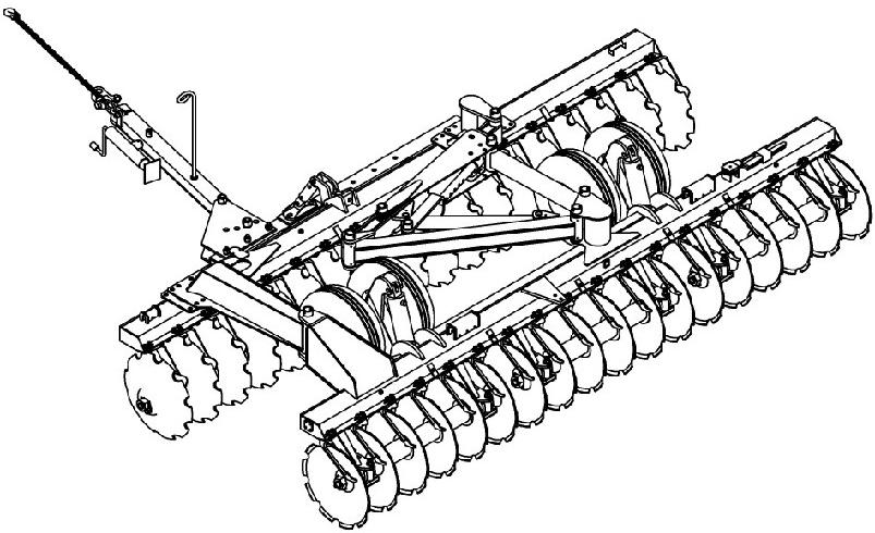
Combines the superior uniform leveling and mixing capability of the hinge harrow with the transportability of a wheel harrow.
Transport wheels with hydraulic control of gangs standard.
New gang assembly design positions the bearing and spacer assemblies behind the gang carriers. This placement provides additional clearance resulting in excellent trash handling capabilities, therefore less clogging.
Reinforced scrapers clean disks more thoroughly.
Full range of adjustment to control depth of penetration. Angle adjustment from 0 to 45 degrees.
Harrow weights from 390 lbs. (176kgs) to 417 lbs. (189kgs) per disk blade, depending on model.
Standard Equipment
32” (813mm) diameter, 3/8” (10mm) thick, cutout (notched), deep concavity disk blades. Adjustable disk blade scrapers.
Tongue jack.
Hydraulic control group includes hydraulic cylinders, hose holder and hoses with fittings and quick couplers to reach rear of tractor.
Heavy duty bearing wear plates.
New Industrial Tires.
Light Group
*Power Take Off Horsepower (PTO-HP) – The amount of horsepower, measured at the PTO respectively, required to move an implement through the soil. Note : HP range provided is an estimate. Power requirements will vary due to key operational conditions such as: soil type, field speed, soil moisture level, penetration depth and others.