3 minute read
Assembly

from Frontier Hinge Wheel Off Set Disk Harrow DH4317 DH4320 Assembly & Operating Instruction Manual(5RPMA

STEP 1. ASSEMBLING GANGS - CONT.
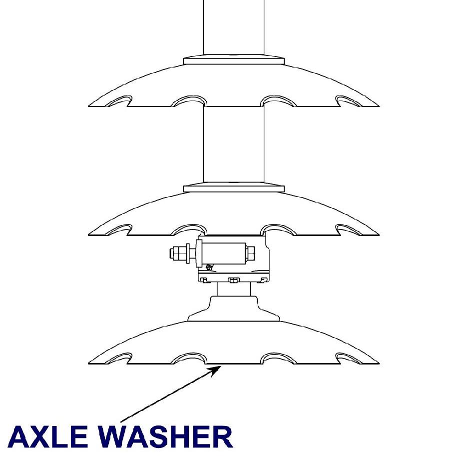
E. Raise the axle into a vertical position. Axle, blade and bearing will now stand in an upright position without being held. If the axle washer is not snug against concave side of the disk blade, it will be necessary to tilt axle and disk blade and slide a short 1" x 4" block of wood underneath the disk. Be sure to position it between the nut and the floor or ground. This assures that the threaded end of the axle will be visible when the gang is completely stacked. Note : If this procedure is not followed, the shaft will be too short and the nut cannot be installed.
CAUTION: Gang components are heavy. Two-person gang assembly is recommended. Follow Safety Guidelines.
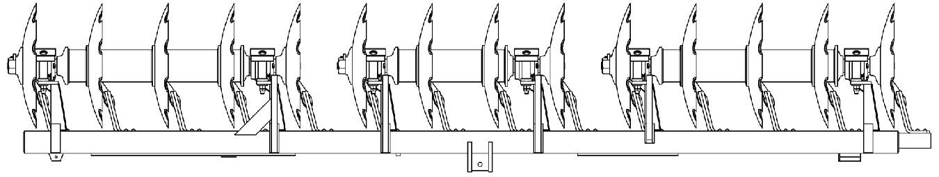
F. Refer to the illustration and continue to slide the disks, spacers, and bearings down the axle exactly in the order shown turn disk blades to make sure that the dimples lock in so the bearings and spacers set all the way against the disk blades. Important: Make sure that concave and convex faces on the washers, bearing assemblies, and disk spacers coincide with the faces of the disks. Note : Concave and convex flanges on the bearing assemblies are factory mounted to correspond to the front and rear gangs in order to have the grease fittings always facing to the rear. This makes it easier to grease the bearings.
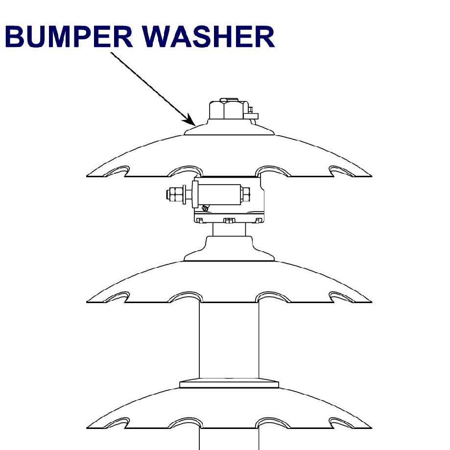
G. After the last disk blade is in place, place the bumper washer onto the axle. Replace axle nut after applying lubricant to axle threads. Tighten to remove all slack. Final tightening should be done in the horizontal position.
H. Use an overhead crane or hoist to lower the disk to the horizontal position on floor. Use chock blocks to prevent rolling. Using the axle nut wrenches, tighten both axle nuts as tight as possible.
For best results and added leverage, place a four or five foot length of 2-inch pipe on each axle nut wrench to serve as handle extensions. It may be necessary to hit the pipe extension with a hammer to meet recommended lbs/ft of torque as set forth in the Torque Chart found in the MAINTENANCE section - TIGHTEN GANG AXLE NUTS. Mount axle nut locks to axle and bumper washers and secure with hex bolts and lock washers.
STEP 2. INSTALLING GANGS ON GANG CARRIERS
Where lifting facilities are available:
A. Position front gang assembly with concave side of disks to right, as viewed from the rear.
B. Position rear gang assembly with concave side of disks to left, as viewed from the rear. Place gang carriers on corresponding gang assemblies and attach to bearing standards with the bearing, hex jam nuts, hex nuts and bearing wear plates.
Where lifting facilities are limited:
A. Position gang carriers upside down. Place gang assemblies on gang carriers and attach to bearing standards with the bearing hex bolts, hex jam nuts, and hex nuts.
B. Turn completed assemblies of gangs and gang carrier right side up. Install disk scrapers.
STEP 3. JOINING GANG CARRIERS
Position the rear gang carrier in a level, upright position by blocking up under the hitch plates and gang carrier. Attach pivot hinge at the hinge point with hinge pin (Note: Clean grease and paint from bushings before installing hinge pin).
Move front gang carrier into position and bolt pivot hinge to front gang carrier with bolts provided (Note: The machined 1 -1/4” x 3” high-tolerance bolts also serve as dowels. A portion of each bolt is not threaded). For operation in most soil conditions, it is recommended that the pivot hinge be bolted approximately in the center of the gang carrier bolting plate. Do Not Fully Tighten!
Install two grease fittings in pivot hinge and lubricate hinge pin.
STEP 4. INSTALLING STABILIZERS AND LATCH GROUP
Attach rear stabilizer and latch support beam to the rear gang carrier with pins provided. Swing the front stabilizer with stabilizer hinge over right plate on front gang carrier (Note : Loosen port plugs on angling cylinder to allow for extension of the cylinder during stabilizer assembly). Bolt stabilizer hinge into position with 1” x 3” bolts provided to coincide with position of pivot hinge (See illustration at right and on following page). Pivot hinge and stabilizer hinge should be bolted in the same relative position on the front gang carrier bolting plates. Important: Do not tighten fully until all bolts have been started!
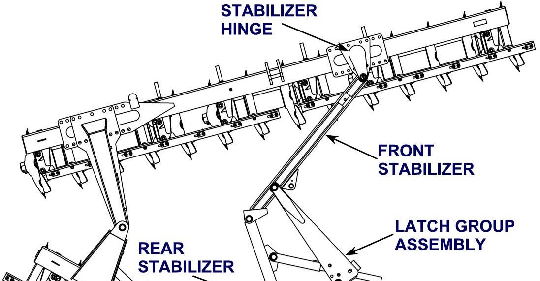
The latch support assembly works in conjunction with the hydraulic angle control system. Its function is to maintain the angle between the front and rear gangs when the harrow is in operation. It also holds the gangs parallel and supports the front gang during transport.

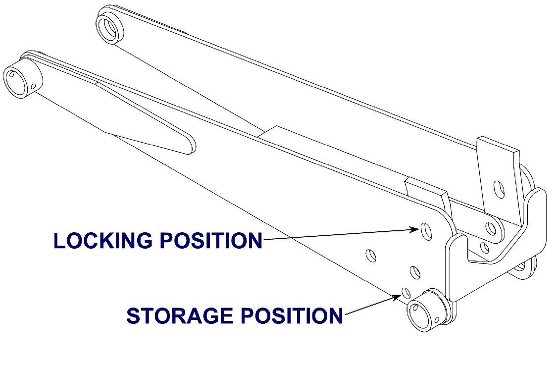
A transport lock pin with a handle and click pin are provided with the latch group assembly to keep the harrow closed during transport. There are two holes in the latch. The storage position hole is located on the backside of the latch support. The locking position hole is located on the front side of the latch support (See illustration below and on following page).