5 minute read
ASSEMBLY


Uncrating Rakes
NOTE: Each crate contains components for two complete machines.
Select an area that has adequate room for parts layout and machine assembly.
Begin assembly by removing all components from the crate. Lay components out individually for ease of locating during assembly.
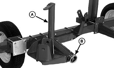
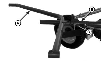
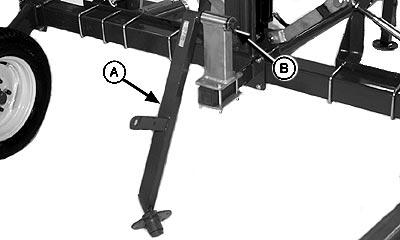
Install Jackstand
1. Install jackstand (A). Fasten with pin (B) and spring-locking pin.
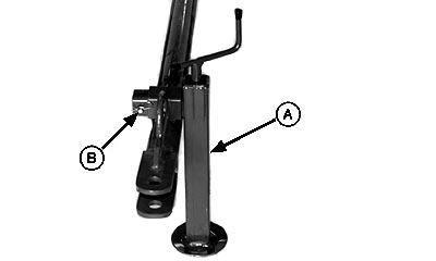
2. Remove assembly stands from under rear frame.
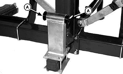
Install Tongue To Rear Frame
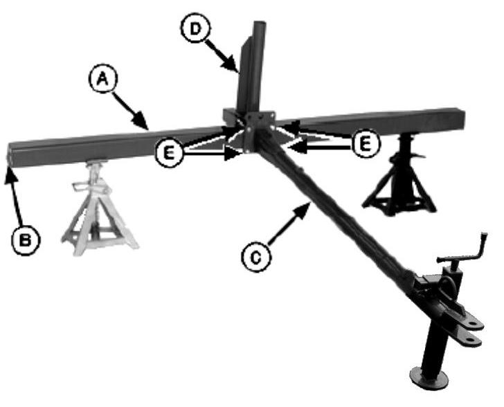
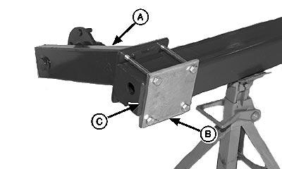
1. Support rear frame (A) on assembly stands. Make sure frame (A) is positioned so drain hole (B) is toward the bottom.
2. Mark the exact center of rear frame. Use mark for tongue installation.
3. Install tongue (C) and cylinder support (D) in the center of rear frame. Fasten with four M12 x 140 cap screws (E), lock washers, and nuts.
A—Rear Frame
B—Drain Hole
C—Tongue
D—Cylinder Support
E—M12 x 140 Cap Screws
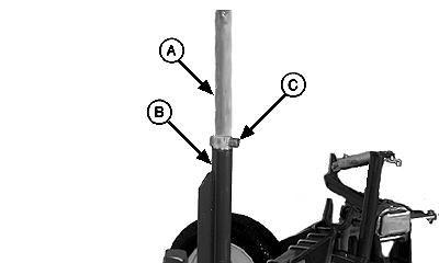
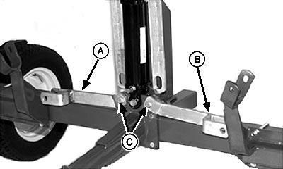
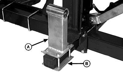
Install Wheels
1. Install wheel support (A) and plate (B) to frame. Make sure plate (B) is to the inside of weld (C). Fasten with four M12 x 140 cap screws, lock washers, and nuts.
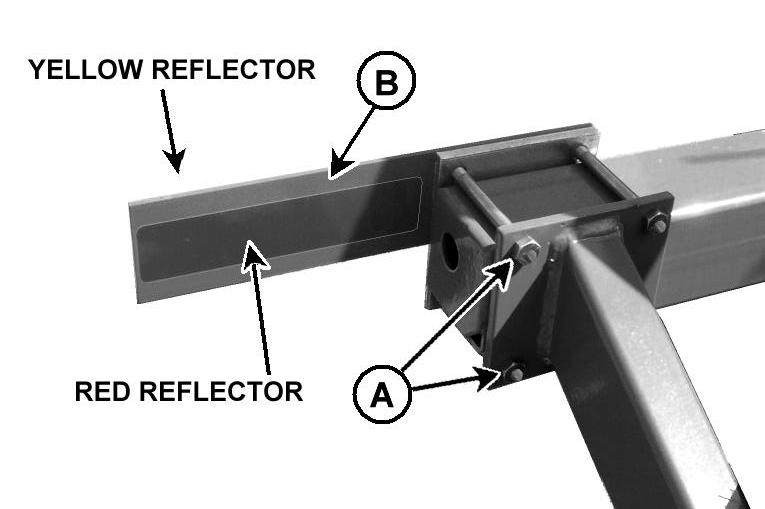
Install Reflectors
1. Remove nuts (A).
2. Install left-hand bracket (B) with red reflector to the rear and the yellow reflector to the front.
3. Install nuts (A).
4.- Repeat procedure on right-hand side. Install bracket with red reflector to the rear .
A—Nuts B—Left-Hand Bracket
Install Wheels
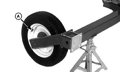
1. Install wheel with valve stem (A) to the outside. Fasten with five M16 lug nuts.
2. Repeat procedure on opposite side.
Assembly
Install Pivot Shaft And Pivot Head Assembly
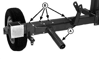
1. Install pivot shaft (A) on rear frame. Fasten with four U-bolts (B), eight M12 nuts. Do not tighten at this time.
2. Remove paint from pivot shaft (A).
3. Grease pivot shaft (A).
4. Install pivot assembly (A) over shaft.
5. Install retaining ring (B). Fasten with M10 x 100 cap screw and lock nut.
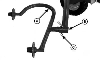
6. Install right-hand support bracket (A) to pivot assembly.
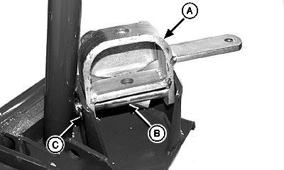
7. Install pin (B) with hole toward the inside. Fasten with cotter pin (C).
Note: On WR1010 & WR1012 there is a right-hand & left-hand support bracket. On WR1008 the support bracket supplied can be mounted both right-hand & left-hand.
Assembly
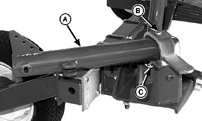
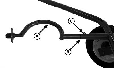
8. Install frame tube (A) to support bracket.
9. Install pin (B) with hole toward the bottom. Fasten with cotter pin (C).
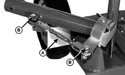
10. Attach float spring (A) to pivot strap (B). Fasten with cotter pin (D).
11. Install M12 x 40 cap screw (E) through float spring (A) in the middle hole of 8-wheel rake or in the top hole of 10 wheel rake, and through middle hole of pivot head bracket (C). Fasten with M12 nut.
Assembly
12. Install turnbuckle (A) to support bracket and frame tube. Fasten with two M16 x 55 cap screws (B) and lock nuts.
13. Repeat procedure on left-hand side.
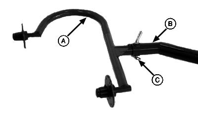
INSTALL HYDRAULIC CYLINDER GUIDE TUBE, CYLINDER, AND LIFT LINKS
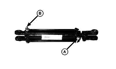
1. Remove two plugs from hydraulic cylinder.
2. Install breather (A) at cylinder rod end.
NOTE: Wrap pipe threads with teflon tape before installing in hydraulic cylinder.
3. Install straight fitting (B) at cylinder barrel end.
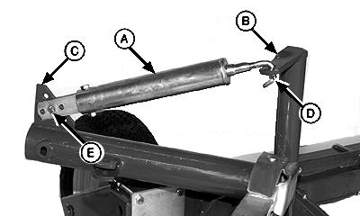
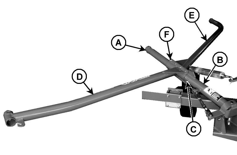
Assembly
4. Apply multipurpose grease to tube (A).
5. Install tube (A) into support (B) with longer spacer (C) toward the front of machine.
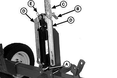
6. Install cylinder barrel end to rear main frame assembly.Fasten with pin (A) and spring clip.
7. Install pin with tab (B) through tube (C), cylinder rod clevis, upper lift links (D), and cylinder rod clevis. Fasten with 3.6 x 25 x 44 mm washer and springlocking pin (E).
Assembly
8. Install right-hand lower lift link (A) and left-hand lower lift link (B). Fasten with two M16 x 55 cap screws (C) and lock nuts.
Install Turnbuckles
1. Attach turnbuckle (F) to right-hand lower lift arm. Install cap screw (A) through washer (B), spacer (C), lower lift arm (D), upper lift arm (E), turnbuckle (F), lower lift arm (G), and lock nut (H).
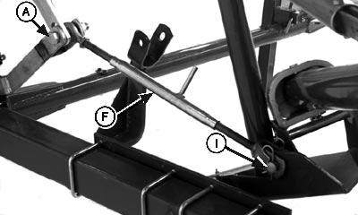
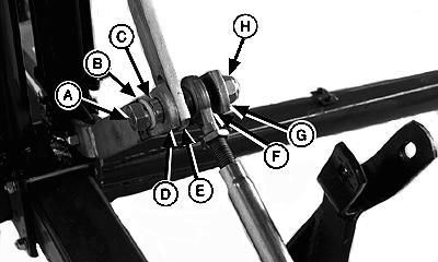
2. Attach turnbuckle (F) to pivot assembly with pin (I). Fasten with two spring-locking pins.
3. Repeat on left-hand side.
A—M20 x 110 Cap Screw
B—Washer
C—Spacer
D—Lower Lift Arm
E—Upper Lift Arm
F—Turnbuckle
G—Lower Lift Arm
H—Lock Nut
I—Pin
Assembly
INSTALL RAKE WHEEL FRAMES (WR1008 & WR1010)
1. Install right-hand wheel main frame (A) to frame tube (B). Fasten with M16 x 85 pin (C), 2.8 x 17 x 30 mm washer, and spring pin.
A—Right-Hand Wheel Main Frame
B—Frame Tube
C—M16 x 85 Pin
2. Identify left-hand wheel frames (A) and right-hand wheel frames (B) .
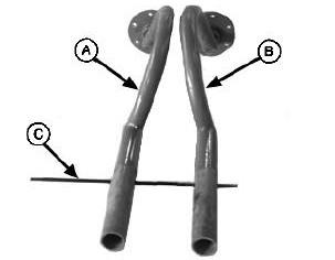
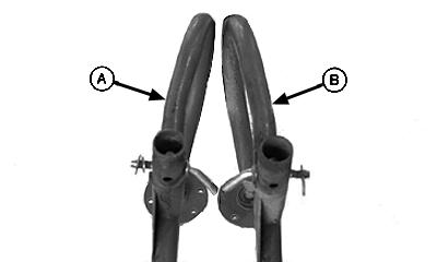
Make sure frames (A) and (B) are installed with the bend in the up position.
To help identify middle wheel frame, install rod (C) through holes in the horizontal position.
Wheel Frames for Main Frame (Middle)
A—Left-Hand Frame
B—Right-Hand Frame
C—Rod
Assembly
INSTALL RAKE WHEEL FRAMES (WR 1012)
1.- Install right-hand wheel central frame (A) to frame tube (B). Fasten with M16 x 85 pin (C), 2.8 x 17 x 30 mm washer, and spring pin. Connect front frame (D) and rear frame (E) to the central frame (A) and fasten with TE M10x30 Screws (F) and klock nuts.
A—Frame Central
B—Frame Tube
C—M16 x 85 Pin
D—Frame Front
E—Frame Rear
F—Screw TE M10x30
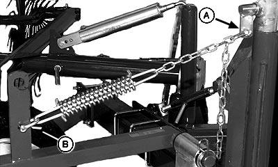
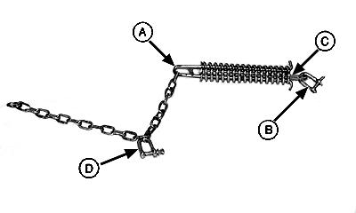
2. Connect the turnbuckle M14 following the order shown in the picture to the right.
A—Rod Frame
B—Chain 54x25x6
C—U Shackle D=8
D—Turnbuckle M14
E—U Shackle D=8
F—Chain 57x33x6 L=720
Assembly
3. Install right-hand wheel frame (A) to the front of right-hand main frame (B). Fasten with M16 x 85 pin, 2.8 x 17 x 30 mm washer, and spring-locking pin (C).
4. Install right-hand wheel frame (A) to the middle of the right-hand main frame (B). Fasten with M12 x 80 cap screw and lock nut (C).
A—Right-Hand Wheel Frame
B—Right-Hand Main Frame (Front)
C—Spring-Locking Pin
A—Right-Hand Wheel Frame
B—Right-Hand Main Frame (Middle)
C—M12 x 80 Cap Screw and Lock Nut
Assembly
5. Install right-hand wheel frame (A) to the rear of right-hand main frame (B). Fasten with pin, 2.8 x 17 x 30 mm washer, and spring-locking pin (C).
6. Repeat procedure on left-hand side.
A—Right-Hand Wheel Frame
B—Right-Hand Main Frame (Rear)
C—Spring-Locking Pin
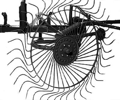
Install Rake Wheels
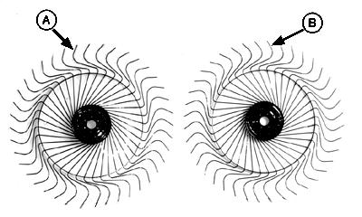
1. Identify and separate left-hand and right-hand rake wheels.
2. Lean rake wheels against a wall with tine mounting clip nuts facing outward.
If the last bend in the tines curve to a clockwise direction, it is a left-hand rake wheel (A).
If the tines curve in a counterclockwise direction, it is a right-hand rake wheel (B).
A—Left-Hand Rake Wheel
B—Right-Hand Rake Wheel
Assembly
3. Install right-hand rake wheel with tine clips to the front. Fasten with six M10 x 25 cap screws, flat washers, and nuts. Install bolt heads to the inside with washers and nuts to the outside.
4. Repeat procedure for remaining rake wheels.
Install Hydraulic Hose
1. Attach hydraulic hose (A) to cylinder.
2. Install hose clamps (B). Fasten with four M6 x 25 socket-head cap screws.
Assembly
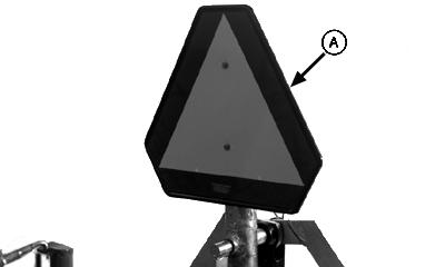
Install Smv Emblem
Install SMV emblem (A) to cylinder guide. Fasten with two M6 x 80 screws, lock washers, and nuts.
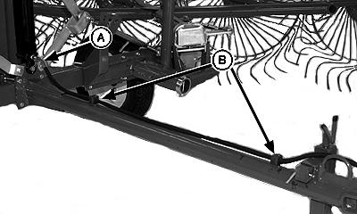
Set Windrow Width
1. Set windrow width to desired setting by sliding pivot frame and adjusting turnbuckle (A).
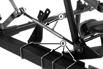
2. Tighten U-bolts (B). Repeat on opposite side.
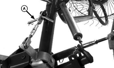
STORE LOCK PINS.
Install lock pins (A) in storage position. Fasten with spring-locking pin.
Installing Center Kicker Wheel
Installation Instruction
Install Wheel
1. Install wheel mounting bracket (A) and plate (B). Fasten with four M12 x 110 cap screws, lock washers and nuts.
2. Install nylon bushings (A) in mounting bracket. Seat bushings with rubber mallet.
3. Install rake wheel arm (A) to mounting bracket. Fasten with 5 x 32 x 53 mm washer (B) and springlocking pin.
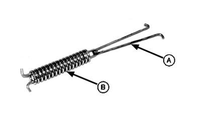
5. Attach chain (A) to V-clip (B).
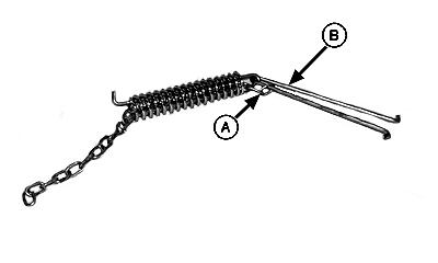
Installation Instruction
6. Push V-clip (A) with chain through spring.
7. Install clevis (B) onto V-clip (C).
8.