1 minute read
Removing the Antennas


IMPORTANT: The LCD Module configuration differs depending on supported functions. Only the 3G model is disassembled in this procedure, though the method is the same.
For 3G enabled models, the LCD Module appears as follows when the LCD Panel is removed: • Blue callout—Main 3G Antenna cable • Yellow callout—Aux 3G Antenna cable • Red callout—Main and Aux WLAN Antennas
For WLAN only models, the LCD Module appears as follows when the LCD Panel is removed: • Blue callout—Main WLAN Antenna cable • Red callout—Aux WLAN Antenna cable

1. See “Removing the LCD Panel” on page 79. 2. Lift all the adhesive strips securing the yellow 3G Antenna cable in place and remove the cable from the cable channel.

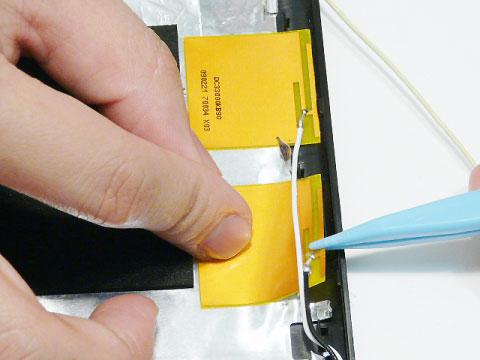
3. Carefully pry up the Antenna pad, as shown, and remove the pad from the LCD Module. IMPORTANT: A strong adhesive is used to secure the Antenna pad in place. Take care not to bend the pad during removal.

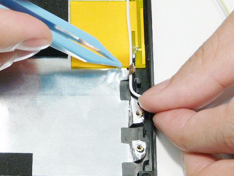
4. Lift all the adhesive strips securing the blue 3G Antenna cable in place and remove the cable from the cable channel.


5. Carefully pry up the Antenna pad, as shown, and remove the pad from the LCD Module. IMPORTANT: A strong adhesive is used to secure the Antenna pad in place. Take care not to bend the pad during removal.

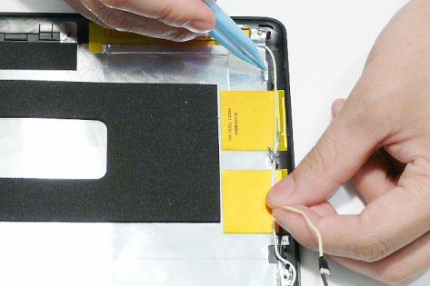
6. Lift all the adhesive strips securing the white and black WLAN Antenna cables in place and remove the cable from the cable channel.
7. Carefully pry up the Antenna pads, as shown, and remove the pads from the LCD Module. IMPORTANT: A strong adhesive is used to secure the Antenna pads in place. Take care not to bend the pads during removal.